Abstract
An expression for the dynamic rolling force of a rolling mill is derived in terms of the vibration and process parameters by analyzing the dynamic rolling process. A nonlinear vibration model of the rolling mill rolls is established. The amplitude-frequency and bifurcation equations are obtained using a multi-scale approximation method, to solve the dynamic equation with time-delayed displacement control. With a 1780 rolling mill as an example, it is found that the primary and cubic stiffness due to the dynamic rolling force and external excitation lead to a jump phenomenon in the vibration system, making it unstable. When the gain coefficient and delay time are taken reasonably, the amplitude of the vibration system is reduced, the resonance region shrinks, and the jump is eliminated. Finally, the bifurcation topological curve corresponding to the transition set of the vibration system is studied using the singularity theory, with and without time-delayed displacement control. The results show that the vibration of the rolling mill rolls can be restrained by varying the initial parameters and through the time-delayed displacement control. Thus, the established vibration model of the rolling mill is verified, and the effectiveness of the time-delayed displacement control in reducing the rolling mill vibration is confirmed.
Highlights
- We derived an expression for the dynamic rolling force and a nonlinear vibration model of the rolling mill rolls is established.
- The results show that when the gain coefficient and delay time are taken reasonably, the amplitude of the vibration system is reduced, the resonance region shrinks, and the jump is eliminated.
- We obtained the transition set of the rolling mill rolls with time-delayed displacement control and discussed the static bifurcation characteristics of the rolls.
1. Introduction
The vibration of rolling mill rolls is a challenging problem for steel enterprises. Extensive studies are being conducted on restraining the vibration to ensure that the system runs smoothly and that the quality of the rolling products is maintained [1-3]. The chatter mechanism and vibration characteristics of rolling mill rolls have been studied from different perspectives [4-6]. Younes et al. [7] established the linear vertical vibration model of a rolling mill and explained the relationship between the change in some process parameters and the type of product defects, which provided a reference for improving the product quality. Peng et al. [8, 9] considered the dynamic characteristics during hot rolling, uneven stress characteristics of the rolling body, and interconnection between various vibration forms. They analyzed the natural characteristics and vibration response of a rolling mill through field test data and numerical simulation, and improved the stability of the rolling mill vibration system. Liu et al. [10] considered the influence of friction coefficient on the horizontal vibration of a workpiece, studied the bifurcation behavior of the vibration system using the singularity theory, and specified the unstable regions of rolling mill vibration. Liu et al. [11] provided a more detailed and quantitative explanation for the regenerative chatter mechanism during rolling, and showed that the time-delay effect reduces the critical rolling speed of mill vibration within a certain range. Zeng et al. [12] established the vertical-horizontal-torsional coupling dynamic model of a rolling mill under the condition of nonlinear friction and calculated the Hopf bifurcation points under different rolling speeds; their research results are useful for optimizing the rolling process. In the vibration analysis of rolling mill rolls, many theories and practices have shown that the rolling force is the key factor affecting the vibration of the system. It is directly related to the research and analysis of the vibration characteristics of rolling mill rolls regardless of whether modeling is reasonable [13, 14]. Wang et al. [15] established a rolling force model considering the friction between the roll gap based on the unsteady lubrication theory. Considering the sliding and adhesive frictions on the contact arc between the hot-rolled strip and the working roll, Chen et al. improved the Karman equation for the hot strip and derived a new rolling force formula [16]. Sun et al. [17]obtained a type of rolling force with a time-delayed characteristic under the influence of roller dynamic movement based on the rolling theory. Zhang et al. [18] introduced the concept of the deformation penetration coefficient to describe the deformation characteristics of an ultra-heavy plate in the thickness direction and found that the coefficient has an obvious effect on the rolling force. Feng et al. [19] found that in high-speed rolling, the distribution of the rolling pressure is affected by the strain rate deformation in the rolling deformation zone; accordingly, rate dependence on the roll force calculation model was proposed. Bu et al. proposed a new method based on the objective function, with the deformation resistance and friction coefficient as the optimization variables, and improved the calculation accuracy of the rolling force to a certain extent [20].
To obtain an accurate vibration model with a more practical vibration characteristic, we analyzed the variation in the parameters in the deformation zone between the rolls, derived a dynamic rolling force expression considering the various vibration and process parameters, and established a nonlinear vibration model of the roll system based on the dynamic rolling force. Moreover, we derived the amplitude–frequency equation of the vibration system using a multi-scale approximation method and a bifurcation equation using the singularity theory. The vibration law and static bifurcation characteristics of the roll system under different rolling and process parameters were analyzed by numerical simulation under uncontrolled and controlled conditions. The correctness of the model and the effectiveness of the time-delayed displacement control for vibration suppression were verified.
2. Nonlinear vibration modeling of rolling mill rolls
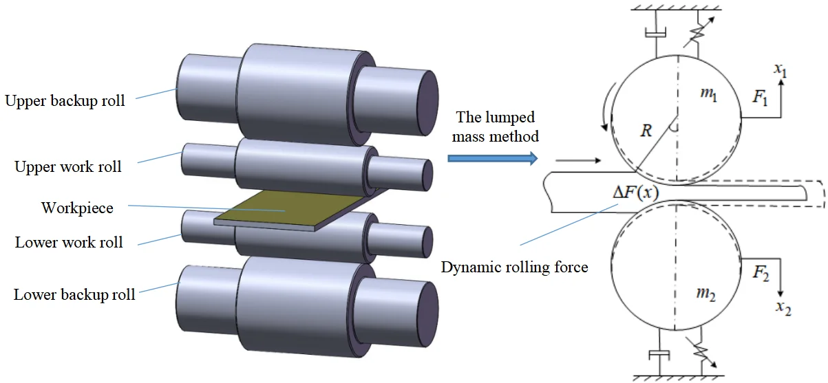
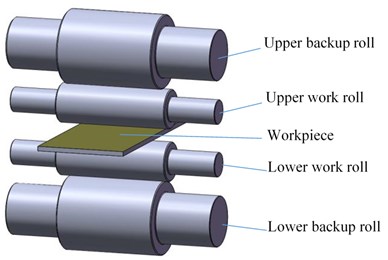
Fig. 1 shows the structural diagram of a four-high hot rolling mill. To facilitate the calculate process, the entire rolling system is made equivalent to a mass block unit using the lumped mass method. Based on the classical mass–spring–damping model and considering the mechanical structure and vibration characteristics of the rolling mill, including the nonlinear process parameters and the rolling force variation during the rolling process, we established a nonlinear dynamic vibration model of the rolling mill rolls, as shown in Fig. 2.
Fig. 1Structural diagram of a four-high hot rolling mill
In Fig. 2, the solid and dotted lines indicate the steady-state and vibration positions of the rolling system, respectively. and are the equivalent masses of the upper and lower rolls, respectively, and are the vibration displacements of the upper and lower roll systems, respectively, and are the periodic external disturbing forces of the upper and lower roll systems, respectively, and is the dynamic variation in the rolling force. and are the equivalent damping parameters between the upper and lower roll systems respectively. A duffing oscillator () is introduced to represent the nonlinear stiffness between the two rolls. and are the linear and nonlinear equivalent stiffness, respectively.
Fig. 2Nonlinear vibration model of hot rolling mill rolls
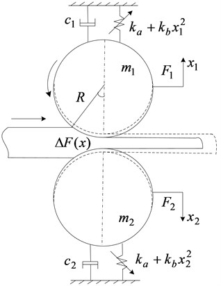
Based on the model shown in Fig. 2, a nonlinear dynamic equation for the rolling mill rolls can be expressed as follows:
Considering the structure of the rolling mill and the symmetry in the vibration form [21], we have , , , and . During vibration, the periodic external disturbance force acting on the rolling mill can be expressed as , where is the external excitation amplitude, and is the time-varying frequency. In this case, the two relationships in Eq. (1) have the same form. Eq. (1) can be further simplified to:
3. Dynamic rolling force
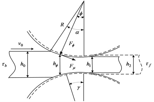
Fig. 3 shows the dynamic rolling process of a workpiece in the deformation area as the rolling mill rolls vibrate.
In Fig. 3, is the roll radius, is the roll linear velocity, is the bite angle, is the neutral angle, is the entry tension, is the exit tension. and are the thickness values of the workpiece at the entry and exit positions in the steady state, respectively. is the thickness of the workpiece at the exit under a vibration condition; ; is the thickness of the workpiece at an arbitrary angle ; . is the unit rolling force, is the unit friction, and , where can be expressed using the Roberts friction factor [22]:
where, , , and are constants with values greater than zero.
Fig. 3Dynamic rolling process diagram of workpiece
According to the classical Bland-Ford force balance theory, which has been used to derive the expression for the dynamic rolling force [23], the deformation zone balance formula can be given as follows:
where, the “+” and “–” symbols indicate the forward and backward slip areas, respectively, and is the resistance to metal deformation, which depends on the chemical composition of the metal materials and the physical conditions of deformation (deformation temperature, deformation speed, and deformation degree). The width is very small, generally , where and are coefficients related to the carbon content of steel strip, and σ is the reduction factor.
Because the arbitrary angle is very small, , 1, and . Considering the influence of entry and exit tensions, we rearrange Eq. (4) and obtain the expressions for the unit pressure in the forward and backward slip areas in the deformation area as follows:
where, , and .
The entire deformation area is divided into two sections for integration. The expression for the total rolling force acting on the roll is as follows:
where, is the width of the workpiece, , , and .
A Taylor expansion is carried out when the vibration displacement 0 on the roll system in the steady state; Accordingly, Eq. (6) can be expressed as:
where, is the steady-state rolling force, and is the dynamic change in the rolling force when the rolling mill vibrates; it is a nonlinear function of the vibration displacement. By substituting Eq. (7) into Eq. (2), we obtain:
In Eq. (8), we set , , , , and . Thus, we can express the nonlinear dynamic equation of the rolling mill rolls based on the dynamic rolling force as follows:
4. Solution to nonlinear amplitude-frequency response of rolling mill rolls with time-delayed displacement control
4.1. Time-delayed displacement control
A time-delayed displacement feedback is introduced into Eq. (9). The modified equation is as follows:
where, is the gain coefficient, and is the delay time.
The nonlinear term in Eq. (10) is given with a small parameter , which is solved using the multi-scale approximation method. We take the solution form of Eq. (11) as follows:
where, and are the different time scales; , and . For time , we can use the differential formula of the composite function to expand by power of :
where, is the sign of the partial differential, ( 0, 1…).
By substituting Eqs. (11) and (12) into Eq. (10) and only taking the approximate solution once, we get:
The solution to the zero-order approximate equation, i.e., Eq. (13), is as follows:
where, is the undetermined complex function, and is the conjugate complex of . By substituting Eq. (15) into the first-order approximation equation, i.e., Eq. (14), we get:
where, is the conjugate complex numbers of the terms on the left.
4.2. Solution to the nonlinear amplitude-frequency response of rolling mill rolls
When the rolling mill rolls vibrate, because and are small and of the same class with a difference of , we have , where is the tuning parameter. To avoid secular terms, function should satisfy:
The complex function is written as an exponential function:
Here, both and are real functions of . By substituting Eq. (18) into Eq. (17) and separating the real part from the virtual, we obtain the first-order ordinary differential equations of and :
where, . For a steady-state response, , , in Eq. (19) can be eliminated, and the amplitude–frequency response equation can be obtained:
Eq. (20) shows that the following parameters influence the vibration system of the rolling mill: damping , primary stiffness , and cubic stiffness due to the dynamic rolling force; excitation amplitude , gain coefficient , and delay time .
4.3. Nonlinear amplitude-frequency characteristics of rolling mill rolls
The relevant vibration parameters of the 1780 hot rolling mill were used for the simulation study. Table 1 lists the parameters and their values.
The nonlinear parameters of the rolling force can be obtained by substituting the data listed in Table 1 into Eq. (7); 2.07×10⁹ N∙m−1, and 2.65×10¹⁵ N∙m−3.
Figs. 4-6 show the amplitude-frequency characteristic curves of the rolling mill rolls with respect to different parameters when the gain coefficient 0, i.e., when the vibration system is not controlled by the time-delayed displacement.
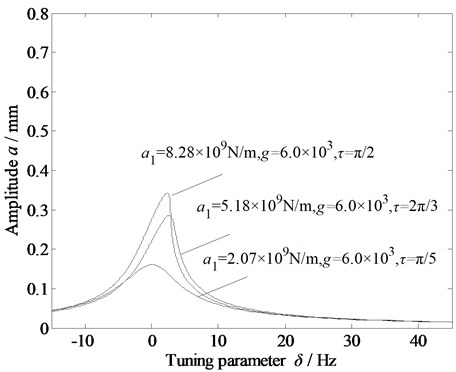
Fig. 4 shows that when the primary stiffness of dynamic rolling force changes, the three curves all shift to the right and are similar; they belong to the phenomenon of jumping. However, with the change in primary stiffness, the amplitude and resonance region of the three curves change slightly, which shows that the primary stiffness has a certain influence on the vibration of the rolling mill. However, the rolling mill cannot be restrained by adjusting the primary stiffness.
Table 1Vibration parameters of 1780 hot rolling mill
Parameters | Value | Parameters | Value |
(m) | 0.42 | (m) | 0.0141 |
(m‧s−1) | 2.5 | (m) | 0.0082 |
(m) | 1.5 | (kg) | 1.44×10⁵ |
(MPa) | 5.5 | (N‧s‧m-1) | 8.85×10⁵ |
(MPa) | 3.8 | (N‧m−1) | 7.95×10⁹ |
(MN) | 0.5 | (N‧m−3) | 1.785×10⁹ |
Fig. 4Amplitude-frequency curve of the vibration system with respect to the primary stiffness due to the dynamic rolling force
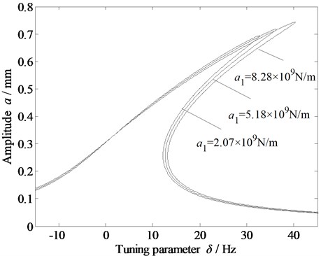
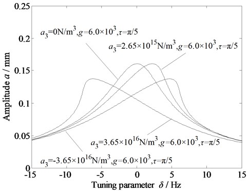
Fig. 5Amplitude-frequency curve of the vibration system with respect to the cubic stiffness due to the dynamic rolling force
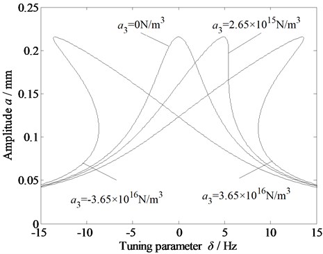
Fig. 5 shows that the cubic stiffness due to the dynamic rolling force does not influence the amplitude variation of the rolling mill vibration system; however, when the value is non-zero, the curve shifts and exhibits a jump phenomenon. In particular, the curve bends to the right when the value is greater than zero, whereas it bends to the left when it is less than zero. With the increase in the absolute value of the cubic stiffness, the vibration region expands, and the greater the bending degree of the curve, the greater the instability of the vibration system. Figs. 4 and 5 show that the dynamic rolling force significantly influences the stability of the vibration system of the rolling mill, thus validating the modeling of the dynamic rolling force.
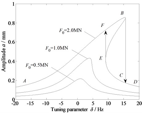
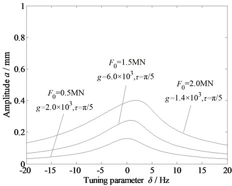
Fig. 6 shows the amplitude–frequency curve with the variation in the external excitation. With the increase in , the amplitude of the system increases, and there are multiple solutions, resulting in a jump. Specifically, when the tuning parameter increases from low to high, the amplitude moves along the path A→F→B→C→D on the curve; when the tuning parameter decreases from high to low, the path is D→C→E→F→A. Clearly, the BE section of the amplitude-frequency curve is an unstable region of forced vibration. In an actual rolling process, the influence of external disturbance on the vibration system of the rolling mill can be alleviated by adjusting the relevant parameters.
Fig. 6Amplitude-frequency curve of the vibration system with the variation in the external excitation
Figs. 7 and 8 show the amplitude-frequency characteristic curves of the rolling mill rolls with different parameters under the variations in the delay time and gain coefficient , respectively. Here, 0, 0 represents the main resonance curve of the original vibration system.
Fig. 7Amplitude-frequency curve of the vibration system with variation in the delay time
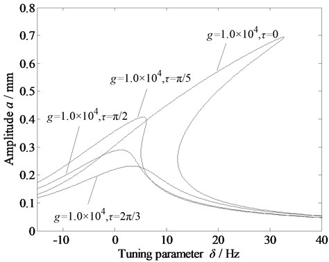
Fig. 8Amplitude-frequency curve of the vibration system with variation in the gain coefficient
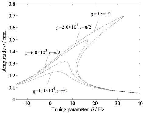
Fig. 9Amplitude-frequency curves of the vibration system under time-delayed displacement control with variations in a) primary stiffness due to the dynamic rolling force; b) cubic stiffness due to the dynamic rolling force; and c) external excitation
a)
b)
c)
In Fig. 7, the gain coefficient g is fixed at 1×10⁴. As the delay time increases, the amplitude of the system decreases, there are no more multiple solutions, and the jump phenomenon disappears. In Fig. 8, the delay time is fixed at /2. As the gain coefficient increases, the amplitude of the system decreases, and the jump phenomenon is alleviated. Therefore, appropriately setting the gain coefficient and delay time can help restrain the vibration of rolling mill systems.
Figs. 9(a)-(c) show the amplitude–frequency characteristic curves of the rolling mill rolls with the variations in the primary and cubic stiffness (due to the dynamic rolling force), and external excitation amplitude under time-delayed displacement control. When the gain coefficient and delay time are appropriately set, the amplitude of the system can be significantly reduced, the multiple solutions can be eliminated, and the vibration of the rolling mill rolls is well controlled. Thus, the time-delayed displacement control is found to be effective in stabilizing the rolling mill vibration.
5. Nonlinear bifurcation characteristics of rolling mill rolls
We applied the singularity theory to study the nonlinear bifurcation characteristics of rolling mill rolls in a dynamic rolling process. Taking , we can rewrite Eq. (20) as follows:
where, and are the unfolding parameters, which indicate that the system will have different bifurcation forms under different values. is the bifurcation parameter, which indicates that the amplitude will change with it under the determined bifurcation mode:
Eq. (21) is the universal unfolding of GS paradigm and the forked point of codimension 2. According to the transition set definition, there are:
1) Bifurcation point set: .
2) Lagged point set: .
3) Double-limit point set: ( is empty set).
4) Transition set: .
Fig. 10Transition set of the nonlinear vibration system of a rolling mill
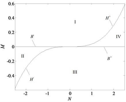
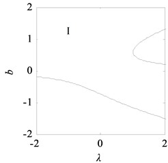
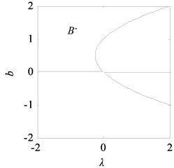
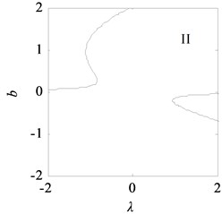
Fig. 11Bifurcation topological curves of rolling mill vibration system without time-delayed displacement control
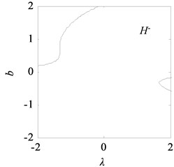
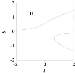
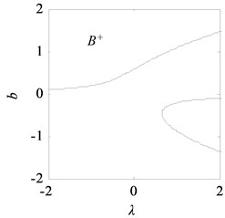
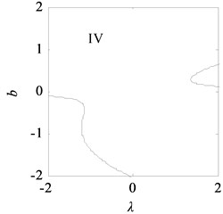
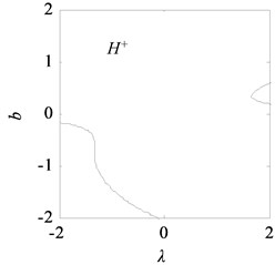
With the data listed in Table 1, the transition set of the nonlinear vibration system can be obtained, as shown in Fig. 10. The bifurcation point set and lagged point set divide the space composed of the unfolding parameters and into four regions: I, II, III, and IV. According to the singularity theory, in the same region, the bifurcation shape of the vibration system is similar, i.e., the bifurcations are persistent, and in the different regions, the bifurcations are different, i.e., the bifurcations are not persistent.
Fig. 11 shows the bifurcation topological curves corresponding to the transition set under no time-delayed displacement control, i.e., when 0. As shown, there is no unstable solution in regions Ⅱ and Ⅳ with the change in , and the system is stable. In regions Ⅰ and Ⅲ, one value of corresponds to multiple values, and the system appears to exhibit the amplitude jump phenomenon. At this time, the rolling mill vibration is in an unstable state. However, the curves of the bifurcation point set and lagged point set contain critical points for multiple solutions. In the rolling process, the bifurcation parameters can be adjusted so that the rolling mill can avoid the curves in regions I and III, which contain the bifurcation point set and lagged point set . This can make the rolling mill system to run stably.
Fig. 12Bifurcation topological curves of rolling mill vibration system with time-delayed displacement control
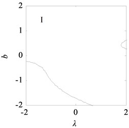
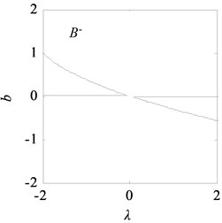
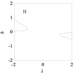
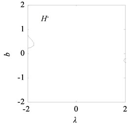
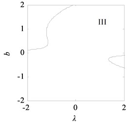
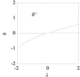
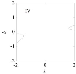

Fig. 12 shows the bifurcation topological curves corresponding to the transition set under time-delayed displacement control when 1.0×10⁴ and . The amplitudes in the different regions of the controlled transition set decrease, the resonance regions in I and III shrink, the multiple solutions on the curves of the bifurcation point set and lagged point set decrease, and the jump phenomenon of the system is eliminated.
6. Conclusions
1) By analyzing the parameter variation in the deformation zone between the roll gap, we derived an expression for the dynamic rolling force in terms of the roll radius, thickness, tension at entry and exit of the workpiece, deformation resistance, friction coefficient, and reduction factor.
2) The difference in the values of the primary and cubic stiffness (due to the dynamic rolling force) and external excitation makes the rolling system to exhibit a jump vibration, resulting in instability. Appropriately setting the gain coefficient and delay time can reduce the amplitude of the system, shrink the resonance region, and eliminate the jump phenomenon, thus ensuring a smooth operation of the vibration system.
3) Using the singularity theory, we obtained the transition set of the rolling mill rolls with time-delayed displacement control and discussed the static bifurcation characteristics of the rolls under uncontrolled and controlled conditions. A smooth operation of the rolling mill vibration system could be ensured by controlling the relevant vibration parameters and avoiding the parameter region and critical state corresponding to the jump phenomenon.
References
-
E. Brusa and L. Lemma, “Numerical and experimental analysis of the dynamic effects in compact cluster mills for cold rolling,” Journal of Materials Processing Technology, Vol. 209, No. 5, pp. 2436–2445, Mar. 2009, https://doi.org/10.1016/j.jmatprotec.2008.05.044
-
A. Heidari and M. R. Forouzan, “Optimization of cold rolling process parameters in order to increasing rolling speed limited by chatter vibrations,” Journal of Advanced Research, Vol. 4, No. 1, pp. 27–34, Jan. 2013, https://doi.org/10.1016/j.jare.2011.12.001
-
R. Peng, X. Zhang, and P. Shi, “Vertical-horizontal coupling vibration of hot rolling mill rolls under multi-piecewise nonlinear constraints,” Metals, Vol. 11, No. 1, p. 170, Jan. 2021, https://doi.org/10.3390/met11010170
-
X. Fan, Y. Zang, and K. Jin, “Rolling process and its influence analysis on hot continuous rolling mill vibration,” Applied Physics A, Vol. 122, No. 12, Dec. 2016, https://doi.org/10.1007/s00339-016-0541-6
-
A. K. Tieu and Y. J. Liu, “Friction variation in the cold-rolling process,” Tribology International, Vol. 37, No. 2, pp. 177–183, Feb. 2004, https://doi.org/10.1016/s0301-679x(03)00048-3
-
I. S. Yun, W. R. D. Wilson, and K. F. Ehmann, “Review of chatter studies in cold rolling,” International Journal of Machine Tools and Manufacture, Vol. 38, No. 12, pp. 1499–1530, Dec. 1998, https://doi.org/10.1016/s0890-6955(97)00133-8
-
M. A. Younes, M. Shahtout, and M. N. Damir, “A parameters design approach to improve product quality and equipment performance in hot rolling,” Journal of Materials Processing Technology, Vol. 171, No. 1, pp. 83–92, Jan. 2006, https://doi.org/10.1016/j.jmatprotec.2005.06.052
-
Y. Peng, M. Zhang, J.-L. Sun, and Y. Zhang, “Experimental and numerical investigation on the roll system swing vibration characteristics of a hot rolling mill,” ISIJ International, Vol. 57, No. 9, pp. 1567–1576, 2017, https://doi.org/10.2355/isijinternational.isijint-2016-611
-
Y. Peng, Y. Zhang, J. Sun, and Y. Zang, “Tandem strip mill’s multi-parameter coupling dynamic modeling based on the thickness control,” Chinese Journal of Mechanical Engineering, Vol. 28, No. 2, pp. 353–362, Mar. 2015, https://doi.org/10.3901/cjme.2015.0109.010
-
H. Liu, B. Liu, J. Jiang, F. Liu, and P. Li, “Nonlinear vibration characteristic of strip mill under the coupling effect of roll-rolled piece,” Journal of Vibroengineering, Vol. 18, No. 8, pp. 5492–5504, Dec. 2016, https://doi.org/10.21595/jve.2016.17056
-
X. Liu, Y. Zang, Z. Gao, and L. Zeng, “Time delay effect on regenerative chatter in tandem rolling mills,” Shock and Vibration, Vol. 2016, pp. 1–15, 2016, https://doi.org/10.1155/2016/4025650
-
L. Zeng, Y. Zang, and Z. Gao, “Hopf bifurcation control for rolling mill multiple-mode-coupling vibration under nonlinear friction,” Journal of Vibration and Acoustics, Vol. 139, No. 6, Dec. 2017, https://doi.org/10.1115/1.4037138
-
M. Kazeminezhad and A. Karimi Taheri, “Calculation of the rolling pressure distribution and force in wire flat rolling process,” Journal of Materials Processing Technology, Vol. 171, No. 2, pp. 253–258, Jan. 2006, https://doi.org/10.1016/j.jmatprotec.2005.06.070
-
W.-G. Li, C. Liu, N. Feng, X. Chen, and X.-H. Liu, “Friction estimation and roll force prediction during hot strip rolling,” Journal of Iron and Steel Research International, Vol. 23, No. 12, pp. 1268–1276, Dec. 2016, https://doi.org/10.1016/s1006-706x(16)30187-x
-
Q. Wang, Z. Jiang, J. Zhao, and M. Fang, “Multi-factor coupling system characteristic of the dynamic roll gap in the high-speed rolling mill during the unsteady lubrication process,” Tribology International, Vol. 67, pp. 174–181, Nov. 2013, https://doi.org/10.1016/j.triboint.2013.07.010
-
S. Chen, W. Li, and X. Liu, “Calculation of rolling pressure distribution and force based on improved Karman equation for hot strip mill,” International Journal of Mechanical Sciences, Vol. 89, pp. 256–263, Dec. 2014, https://doi.org/10.1016/j.ijmecsci.2014.09.011
-
J. Sun, “Vertical vibration of moving strip in rolling process based on beam theory,” Chinese Journal of Mechanical Engineering, Vol. 22, No. 5, p. 680, 2009, https://doi.org/10.3901/cjme.2009.05.680
-
S. H. Zhang, L. Deng, Q. Y. Zhang, Q. H. Li, and J. X. Hou, “Modeling of rolling force of ultra-heavy plate considering the influence of deformation penetration coefficient,” International Journal of Mechanical Sciences, Vol. 159, pp. 373–381, Aug. 2019, https://doi.org/10.1016/j.ijmecsci.2019.05.048
-
X. Feng, X. Wang, Q. Yang, and J. Sun, “Analysis of rate dependency on roll force calculation during hot strip rolling based on Karman equation,” Advances in Mechanical Engineering, Vol. 11, No. 1, p. 168781401882493, Jan. 2019, https://doi.org/10.1177/1687814018824931
-
H.-N. Bu, Z.-W. Yan, and D.-H. Zhang, “A novel approach to improve the computing accuracy of rolling force and forward slip,” Ironmaking and Steelmaking, Vol. 46, No. 3, pp. 269–276, Mar. 2019, https://doi.org/10.1080/03019233.2017.1369681
-
P.-H. Hu, H. Zhao, and K. F. Ehmann, “Third-octave-mode chatter in rolling. Part 1: Chatter model,” Proceedings of the Institution of Mechanical Engineers, Part B: Journal of Engineering Manufacture, Vol. 220, No. 8, pp. 1267–1277, Aug. 2006, https://doi.org/10.1243/09544054b06804
-
W. L. Roberts, “Third-octave-mode chatter in the cold rolling of light-gage strip,” in Proceeding International Conference on Steel Rolling, Vol. 2, pp. 1215–1224, 1980.
-
D. R. Bland and H. Ford, “The calculation of roll force and torque in cold strip rolling with tensions,” Proceedings of the Institution of Mechanical Engineers, Vol. 159, No. 1, pp. 144–163, Jun. 1948, https://doi.org/10.1243/pime_proc_1948_159_015_02
Cited by
About this article

This research was supported by Science and Technology Research Project of Jiangxi Education Department (No. GJJ211520), and School-level Topics of Nanchang Institute of Science and Technology (No. NGKJ-21-01).
