Abstract
Vibration technological machines with self-synchronized unbalanced vibration exciters (vibrating conveyors, vibrating screens, vibrating crushers, etc.) are widely used in modern industry. Despite drive construction simplicity throughout exploitation of such machines a number of nonlinear dynamics effects can be observed. Most of such effects are related to machine drive and elastic suspension interaction and appear while passing through resonant frequencies. Nowadays the idea of resonant vibrating machines creation got a second breathe. The distinctive feature of such machines is the automated system for maintaining resonant mode of machine. Creation of such automated systems requires accurate mathematical models of vibrating machines that can reflect its most important features. The aim of this work is to create a spatial mathematical model and determine the dynamic system unknown parameters of a vibrating screen experimental sample with two self-synchronizing unbalanced vibration exciters that can create the working body spatial motion. The mathematical model motion equations are derived using the Lagrange equations of the second kind. Using the obtained experimental data (natural frequencies and logarithmic damping decrement), the mathematical model mass-geometric parameters and the damping parameters values were calculated. The investigation result is a verified mathematical model of a vibrating screen sample with two self-synchronizing unbalanced vibration exciters.
1. Introduction
In modern industry, vibrating technological machines (vibrating conveyors, vibrating screens, vibrating crushers, etc.) are widely used [1-3]. Nowadays, self-synchronizing unbalanced vibration exciters based on asynchronous electric motors with a squirrel-cage rotor [1, 3, 4] are widely used as drives of vibration technological machines. In the induction motors with the elastic system of a vibrating machine interaction, various nonlinear effects are often observed, manifested in the form of jumps in the working body oscillations frequencies and amplitudes [2, 3, 5, 6]. When using several unbalanced vibration exciters, the possibility of self-synchronization phenomenon usage is crucial [1, 3, 7].
In most cases, modern vibrating technological machines with unbalanced vibration exciters operate in a resonant mode, when the frequency of forced vibrations exceeds the natural frequency of the working body [1, 4]. This mode allows to ensure the machine vibration stability in a wide range of load parameters. However, due to the need to overcome resonant frequencies, it is necessary to use electric motors with excess power [8, 9]. This leads to the fact that in the operating mode the drive motor is significantly underloaded, as a result of which energy consumption increases and its service life decreases. In addition, the excess electric drive power narrows the frequencies range of unbalances synchronous rotation when using several self-synchronizing vibration exciters [5, 7].
One of the creating energy-efficient vibrating machines principles is based on the use of working body resonant modes of vibration. At the same time, the required masses of unbalances and electric motor power are significantly reduced, which leads to an increase in the efficiency and service life of vibration exciters [3, 10, 11]. However, maintaining such an operation mode requires the use of automated systems for collecting, processing and analyzing information about the current state of the machine dynamic characteristics with the control actions simultaneous formation [3, 10-12]. The creation of rational systems for automatic control for vibration machines is based on a mathematical model of a machine, which should take into account the essential features of its dynamic properties (dynamic system with an engine interaction, self-synchronization various types stability areas, dynamic system to regulation response, etc.).
The purpose of this study is to develop a design scheme and a mathematical model of a vibrating screen with two self-synchronizing unbalanced vibration exciters that can create a working body spatial motion. To achieve this goal, the following main tasks are solved in the work: the machine design scheme formation and its modeling based on the motion differential equations, the parameters identification of the machine design scheme based on the experimental studies results.
2. Calculation model
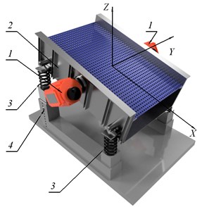
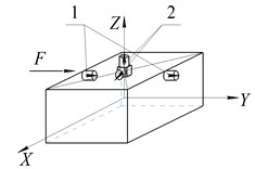
The existing designs of screens, basically, use the layout of two unbalanced vibration exciters, the axes of rotation of which are perpendicular to the vertical plane passing through the technological axis of the machine (the main movement of the processed material direction) [1, 4, 13]. A feature of the machine design considered in this work is that the axes of both unbalanced vibration exciters rotation are located in vertical planes parallel to the technological axis of the machine. Fig. 1 shows such a vibrating screen model, where it is indicated: 1 – vibration exciters; 2 – working body; 3 – springs of elastic suspension, 4 – movable support of the bed; – the direction of the technological axis of the machine.
Fig. 1Vibration screen model
The calculating scheme of the machine is presented on Fig. 2. The working body movement is described relative to the global coordinate system , the beginning of which at rest coincides with the position of the center of mass of the system . The working body is modeled by an absolutely rigid body of mass of length and width . The position of the unbalances and the spring fixing points are set in the local system , rigidly connected with the working body and the reference point coinciding with the origin of the system , and the axes and coincide, and the axes and form an angle – the angle of the working body inclination. The inertia moments of the working body around the axes , , are designated , , , respectively. Angular vibrations are described using the Krylov-Bulgakov angles [14, 15], which in Fig. 2 to simplify the figure are presented as the angles of working body rotation , , around the axes , and . As a result, the working body position relative to the global coordinate system can be specified using six coordinates: three displacements , , and three angles , , .
Fig. 2Calculation scheme of mathematical model
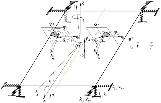
The fastening points of the springs are located in the working body corners, and are displaced by a distance along the axis, which determines the level of oscillations along the and axes with rotations and , respectively connectedness. It is believed that each of the elastic suspension springs has linear characteristics of stiffness in three mutually perpendicular directions with the coefficients , , , which in the design scheme is represented by three elastic elements whose axes are parallel to the global coordinate system, and (in Fig. 2 and hereinafter these coefficients are denoted as ). Damping in the system is only due to the energy dissipation in the springs and is described by a linear viscous friction model with coefficients , , , and .
In the design scheme, each vibration exciter has one unbalance of mass , eccentricity and inertia moment ( 1,2 is the vibration exciter number) fixed in the plane. Each unbalance position in the local coordinate system is described using an additional local coordinate system . The position of the local coordinate system is specified by the radius vector, where and are the modulus and the inclination angle of the radius vector to the positive direction of the axis, and the inclination angle of the axis to the axis, measured from the axis positive direction counterclockwise. The unbalance position angles are counted from the axis negative direction counterclockwise.
The vibration exciters asynchronous electric motors have torque characteristics . To determine the direction of the motors rotation, the parameter ± 1 is used, where the positive value corresponds to the rotation direction of the -th unbalance counterclockwise, and the negative value corresponds to the clockwise direction.
To connect the local coordinate systems and , the rotation matrix is used:
The equations of the system motion, which are obtained using the Lagrange equation of the second kind and geometric rotation matrices, have the form:
where is the column vector of displacements, , and are symmetric matrices (8×8) of masses, stiffness rates and damping, respectively, – is the column vector of nonlinear functions describing the disturbing effect arising from the unbalances rotation.
The components of the mass matrix are as follows:
The components of the mass matrix are as follows:
The components of the mass matrix are as follows:
The vector components of nonlinear functions are as follows:
where is the -th electric drive driving moment, is the rotation resistance moment of the -th unbalance, the index ( + 6) is equal to 7 or 8 depending on 1, 2, the index 1…8.
3. System parameters identification
The obtained equations of motion of a vibrating screen contain parameters, a number of which may be known in advance, while others must be determined from direct or indirect measurements carried out on a specific sample of the screen.
3.1. Mass-geometric parameters identification
The system parameters , , , , , can be determined from the equation:
where is the column vector of squares of natural frequencies, the number of which corresponds to the working body degrees of freedom number, and are the matrices of masses and stiffness, which are obtained from the matrices and included in the equations of motion of the working body Eq. (2), at 0, 0 and = 0.
The Eq. (7) is an equation of the sixth degree relative to the square of the natural frequency. To determine the parameters , , , , , , the inverse problem of dynamics is solved, when the components of the matrices and are calculated from the values of natural frequencies known from the experiment. From the solutions obtained, those in which the values of differ significantly from the known one are discarded, as well as those that do not satisfy physical and geometric representations. The damping parameters were estimated using the experimentally obtained envelope of damped oscillations by varying the logarithmic damping coefficient in the equation of the form . The viscous friction coefficient was calculated by the formula , where is the corresponding natural vibration frequency.
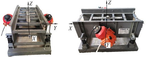
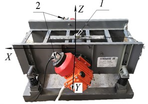
The required system parameters were determined from specially set experiments performed on an experimental sample of a vibrating screen manufactured by NPK “Mekhanobr-Tekhnika” at an angle of the working body inclination 0 (Fig. 3).
Fig. 3The screen experimental sample photograph
Oscillations of the working body were excited in the direction of one of the global coordinate system axes of the vibrating machine by hitting the working body with a dynamometric hammer. The vibrations of the working body were measured using piezoaccelerometers of the AP2038P-50 type. The data obtained were processed in the Wolfram Mathematica 10 software package, the envelopes of damped oscillations were constructed, and the center of mass vibration acceleration spectra along the global coordinate system axes were calculated using the fast Fourier transform.
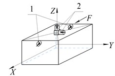
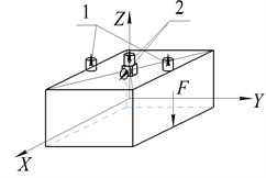
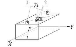
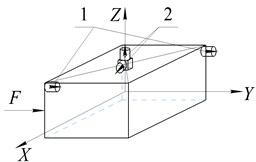
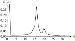
Translational vibrations along each of the three axes of the global coordinate system were measured by two accelerometers 1 in the direction of the impact. Table 1 shows the layout of the sensors on the body of the vibrator and the spectra of the processed signal. In this case, the accuracy of striking a blow relative to the corresponding axis of the screen was controlled using auxiliary sensors 2 installed perpendicular to the direction of the disturbing effect, i.e. with an accurate impact application, the signal level from the sensors 2 should be significantly lower than from the sensors 1.
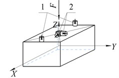
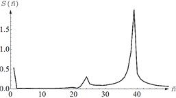
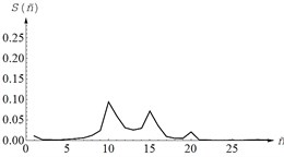
The measurements of the angular vibrations of the body were made according to signals from two sensors 1 installed at a given distance, and their sensitivity axes were located parallel to the line of action of the disturbing effect. The blow was applied to one of the corners of the body, which leads to disturbance of both angular and translational vibrations of the working body. Table 2 shows the arrangement of sensors on the schematic vibrating machine body and an example of the signal spectra of the sensors 1.
The received signals from the main sensors 1 were processed in the Wolfram Mathematica 10 software package and, using the fast Fourier transform, the vibration acceleration spectra of the center of mass along the main coordinates were calculated.
The presence of several peaks in the signal spectrum indicates the connectivity of angular and translational oscillations. As a result of processing the experimental data, 6 natural frequencies of vibrations of the working body of the vibrating machine were calculated 6.5 Hz, 6.35 Hz, 7.5 Hz, 10.2 Hz, 12.6 Hz, 9.3 Hz, according to the values of which the following values were obtained system parameters: 0.456 kg·m2, 0.478 kg·m2, 1.036 kg·m2, 10475 N·m-1, 13141 N·m-1, 0.054 m. Model parameters and were calculated from known dimensions screen and distance .
Table 1Arrangement of sensors on the body of a vibrating machine when measuring translational vibrations and spectra of the main sensors
Along axis | Along axis | Along axis |
 |  |  |
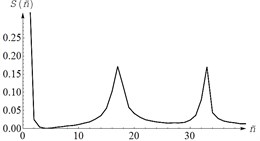 | 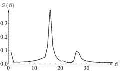 | 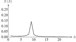 |
Table 2Layouts of sensors on the body of a vibrating machine when measuring angular vibrations and spectra of the main sensors
Along axis | Along axis | Along axis |
 |  |  |
 |  |  |
3.2. The torque characteristics of drive motors parameters identification
On the laboratory sample of the screen, vibration exciters are installed with a rated power on the shaft 0.09 kW and an idle speed (in the absence of a load on the shaft) = 157 rad·s-1, where 50 Hz is the frequency of the supply voltage, 2 – the number of poles of the electric motor. The torque characteristic of the electric motor will be described using the Kloss formula [16]:
where is the critical moment of the electric motor, is the frequency at which the critical moment is reached.
The connection between rated starting and critical torque is recommended to be set in the ranges: (0.4...0.6), (0.83...1.1). In this work, it is assumed: 0.5, . Then the unknowns and are determined from the system:
The nominal torque of the electric motor is and the critical torque .
As a result of the calculation, the following parameters of the drive electric motors were calculated: 115 rad·s-1, 146 rad·s-1, 0.616 N·m, 1.232 N·m.
4. Mathematical model verification
The verification obtained mathematical model was carried out by comparing the calculated and experimental dependences of the steady oscillations acceleration amplitudes along the axes , , on the unbalances rotation frequency
4.1. Experimental study
To conduct the experiment, a three-axis accelerometer 1 (AP2038P-10) and two encoders 2 (E40H8-2500-6-L5) on the axes of vibration exciters were fixed on a laboratory sample of a vibrating screen (Fig. 4).
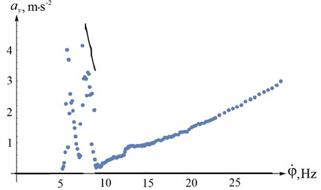
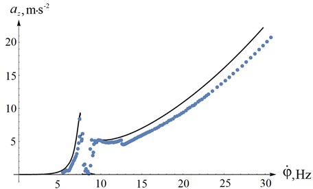
The motors were supplied from a frequency converter with a current frequency varied according to a proportional law in the range from 10 to 60 Hz with a variable step 0.1...1 Hz, depending on the distance from the resonance frequency region. The power supply frequencies were changed after the system oscillations were established. As a result of processing the experimental data, the maximum amplitudes of accelerations and the averaged frequency of rotation of the unbalances of steady-state oscillations were obtained at each frequency of the supply voltage, which is shown by dots in Figs. 5-7.
Fig. 4The sensors on the screen experimental sample
4.2. Calculation results
When calculating the dependence of the amplitude of acceleration on the frequency of rotation of the unbalances, the effect of changing the supply voltage frequency was taken into account. As a result of taking into account the law of frequency regulation, Kloss’s formula takes the form [10]:
where is the displacement of the torque characteristic of the electric motor caused by a change in the frequency of the current . In the range –30 ... 157 rad·s-1 (which corresponds to a change in the supply frequency in the range 0 ... 60 Hz) a series of 400 calculations was carried out, the results of which are the maximum amplitude of the center of mass accelerations during steady oscillations and the rotation speed of the unbalances at a given current frequency. Taking into account that the fixing point of the accelerometer in a full-scale experiment is above the center of mass, the projections of the acceleration vector of this point of the working body on the axis of the global reference frame can be obtained by the formulas , , , which makes it possible to plot the dependence of the amplitudes of the acceleration of steady-state oscillations of the same point where the accelerometer was fixed along the axes , , depending on the unbalance rotation frequency (Figs. 5-7, solid line).
Fig. 5The amplitudes of the acceleration of steady-state oscillations along OX axis
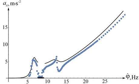
Fig. 6The amplitudes of the acceleration of steady-state oscillations along OY axis
4.3. Results comparison
Comparison analysis of the obtained figures showed satisfactory coincidence of the calculated and experimental characteristics of the system, which, among other things, indicates the correct parameters determination of the vibrating screen laboratory sample.
It is worth noting the accurate coincidences of the unbalances type of synchronization areas change (7.5-9 Hz), and the accelerations amplitudes at natural frequencies.
The existing discrepancies between the model and the experiment can be explained by the natural difference in the parameters of the drive electric motors and unbalances, as a result of which one unbalance lags behind the other during synchronous rotation, which leads to the appearance of a small disturbing force in the direction of the axis during the experiment. In the mathematical model, the motors and unbalances are exactly the same and oscillations along the axis occur only in case of a change in the synchronous rotation type of the unbalances.
Fig. 7The amplitudes of the acceleration of steady-state oscillations along OZ axis
5. Conclusions
As a result of the study, a vibrating screen design scheme and a mathematical model with the spatial motion of the working body were developed, taking into account the torque characteristics of vibration exciters asynchronous electric motors and their rotation speed frequency regulation. The model describes such features of the dynamic screening system as the variable inclination angle of vibration exciters axes of rotation, the possibility of changing the inclination angle of the working body, the connectivity of angular and longitudinal vibrations.
A series of experiments was carried out to determine the unknown parameters of the obtained mathematical model. On the obtained data basis, the inverse problem of finding unknown parameters is solved.
To verify obtained mathematical model, another series of experiments was carried out, as a result of which translational accelerations amplitudes depending on the averaged frequency of the unbalances rotation are obtained.
The obtained mathematical model verification was carried out using comparison of the steady oscillations acceleration amplitudes dependences along the main axes of the installation.
Solutions comparison of the obtained motion differential equations system showed satisfactory coincidence of the calculated and experimental characteristics of the system, which, among other things, indicates the correct parameters determination of the vibrating screen laboratory sample.
The results obtained in carrying out numerical experiments correspond to the physical concept of the processes occurring in the dynamic system of a vibrating technological machine.
The proposed mathematical model and universal algorithm for determining the parameters of a vibrating machine can be used to study the behaviour of vibrating technological machines with a similar design scheme.
References
-
I. I. Blekhman, Vibration Mechanics and Vibration Rheology (theory and applications), (in Russian). Мoscow: Fismatlit, 2018.
-
I. Vulfson, “Dynamics of Cyclic Machines,” in Foundations of Engineering Mechanics, Cham: Springer International Publishing, 2015, https://doi.org/10.1007/978-3-319-12634-0
-
I. Y. Fedorenko, Vibration Processes and Devices in Agro-Industrial Complex: Monograph, (in Russian). Barnaul: EPD of Altai State Agrarian University, 2016.
-
L. A. Vaisberg, Design and Calculation of Vibrating Screens, (in Russian). Moscow: Nedra, 1986.
-
I. I. Blekhman, Vibrational Mechanics: Nonlinear Dynamic Effects, General Approach, Applications. World Scientific Publishing Company, 2000.
-
R. H. Rand, R. J. Kinsey., and D. L. Mingori, “Dynamics of spinup through resonance,” International Journal of Non-Linear Mechanics, Vol. 27, No. 3, pp. 489–502, May 1992, https://doi.org/10.1016/0020-7462(92)90015-y
-
I. I. Blekhman, Synchronization of Dynamic Systems, (in Russian). Moscow: Nauka, 1973.
-
I. I. Blekhman, V. B. Vasil’Kov, and N. P. Yaroshevich, “On some opportunities for improving vibration machines with self-synchronizing inert vibration exciters,” Journal of Machinery Manufacture and Reliability, Vol. 42, No. 3, pp. 192–195, May 2013, https://doi.org/10.3103/s1052618813030023
-
I. I. Blekhman, L. I. Blekhman, V. B. Vasilkov, and L. A. Vaisberg, “Energy consumption in vibrational transportation and process machines,” Obogashchenie Rud, pp. 18–27, Feb. 2019, https://doi.org/10.17580/or.2019.01.03
-
I. P. Lyan, G. Y. Panovko, and A. E. Shokhin, “Comparative analysis of energy efficiency in the use of vibration-type process machines in resonant and superresonant operating modes,” Obogashchenie Rud, No. 6, pp. 42–49, Dec. 2019, https://doi.org/10.17580/or.2019.06.08
-
N. N. Dentsov, “Prospects for the development of resonant vibration technology,” (in Russian), Modern Trends in the Development of Science and Technology, Vol. 2, No. 2, pp. 66–68, 2015.
-
V. K. Astashev and K. A. Pichugin, “Resonant tuning and vibration parameters of the bar system with a piezoelectric exciter,” Journal of Machinery Manufacture and Reliability, Vol. 48, No. 6, pp. 535–540, Nov. 2019, https://doi.org/10.3103/s1052618819030026
-
E. E. Levendel, Handbook: Vibration in Technics. Vol. 4. Vibration Processes and Machines, (in Russian). Moscow: Mashinostroenie, 1981.
-
V. F. Zhuravlev, Fundamentals of Theoretical Mechanics, (in Russian). Moscow: Fizmatlit, 2008.
-
V. O. K. R. F. Ganiev, Oscillations of Solids, (in Russian). Moscow: Nauka.
-
Norm Kopp, A. Hamid Toliyat, and B. Gerald Kliman, Handbook of Electric Motors. CRC Press, 2018, https://doi.org/10.1201/9781420030389
Cited by
About this article

The reported study was funded by RFBR, Project number 20-38-90211.
