Abstract
The objective of this paper is to investigate the self-synchronization of two homodromy rotors coupled with a pendulum rod in a far-resonant vibrating system. Using the average method and revisionary small parameters, we derive the dimensionless equation of the self-synchronization criterion and synchronous stability of the vibrating system. Meanwhile, to prove the correctness of the theoretical analysis, the diversity feature of the vibrating system is simulated numerically. Both results of theoretical analysis and numerical simulation show that increasing the length of the pendulum rod or decreasing the mass of the rotor connected with pendulum rod can ensure the self-synchronization and synchronous stability of two homodromy rotors in the vibrating system.
1. Introduction
Synchronization phenomena can be easily found in nature, such as fish swimming in same direction, the earth motion rotating around the sun, film synchronizing sound, etc. The synchronous regime arises due to natural properties of the processes themselves and their natural interaction. Since Hugenii [1] studied the synchronization of the clock on a ship in 1673, his work have attracted the attention of many scientists, i.e., synchronization in acoustic and electro-acoustic system was discovered by Raleigh [2] at the nineteenth century, and Pol [3] observed the synchronization of certain electrical-mechanical system. They called synchronization as ‘frequency capture’ or ‘frequency synchronization’.
A well-known example is frequency synchronization of oscillating or rotating bodies, which is called self-synchronization. In the 1960s, Blekhman [4-5] studied the self-synchronization theory of mechanical rotors in the stand point of nonlinear science and wrote some monographs related to the synchronization. Later, Blekhman [6-7] investigated controlled synchronization of two vibroactuators based on a speed-gradient. Wen and Zhao [8] applied such synchronization theory to engineering and proposed the utilization engineering of vibration, and many self-synchronous vibrating machine were invented at the same time. Recently, considering the variable parameter of angular velocity of motors they proposed the small parameter and averaging method by revising Blekhman’s method, meanwhile, Wen and Zhao employ this method and experiments to investigate the synchronization of rotors of different vibrating systems [9-14]. In addition, Balththazar [15-16] et al. dealt with self-synchronization of two and four non-ideal exciters. The aforementioned investigation are mainly for the synchronization of rotors or exciters in vibrating system, and the phenomenon of the synchronization of the pendulum rods hanging on a common moveable has became a research subject by a number of authors recently [17-21].
In this paper we consider the self-synchronization of two homodromy rotors coupled with a pendulum rod in a far-resonant vibrating system, which is devoted to design and analysis of the self-synchronization system for mechanical system with two rotational, one pendular and one translational DOF. Such a configuration represents one possible simplified model of a rotor-pendulum-mass vibrational unit. Because of the complex nonlinear dynamics it is difficult to study its behavior analytically, and numerical simulation becomes the only tool for the investigation. The key to investigate theory of synchronization for such system on a rigid platform is that the coupling characteristics between the rotor and the pendulum rod must be perfectly understood, and this is beneficial to invent new type of vibrating screens.
This paper is organized as follows. Section 2 describes the considered model and motion equations of the vibrating system. In Section 3 we derive the self-synchronization criterion and the stability of self-synchronous state. Section 4 presents the results of our numerical simulations. Finally, we summarize our results in Section 5.
2. The dynamic model
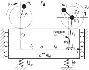
The basic specifics of both the formulation and solution of the synchronization problem for the vibrating system, as well as many features of the phenomenon, may be discovered by using the simplest model related to self-synchronization of debalanced rotors located on an absolutely rigid platform with one degree of the freedom (see Fig. 1). The rigid platform is movable in the -direction, but fixed in the -axis. The platform is connected with the foundation by an elastic element (stiffness coefficient ) and a linear damping element (resistance coefficient ). One unbalanced rotor is directly fixed on the platform and the other is mounted on a rigid pendulum rod. The axes of all the unbalanced rotors driven by identical induction motors are perpendicular to the plan of . The pendulum rod is connected with the platform by a torsion elastic element (torsion stiffness coefficient ) and a linear damping element (resistance coefficient ). Displacement of the platform from a position corresponding to the unconstrained elastic elements, displacement of the pendulum rod from a position corresponding to the unconstrained torsion elastic element, and rotor rotation angles and , counted from the -axis direction in an anticlockwise direction, are assigned as generalized coordinates of the system. Then expressions for kinetic and potential energy of the system can be written as follows:
where is the mass of the platform, and (1, 2) are the mass and inertia moment of unbalanced rotor about the axis passing through its center of mass, respectively. and are the mass and inertia moment of the induction motor about the axis passing through its mass center, respectively. is the vertical displacement of the platform from the equilibrium position. is the eccentricity of unbalanced rotors. is the length of the pendulum rod. Symbols and denote and , respectively:
The viscous dissipation function of the system can be expressed in form:
where and are bearing friction of rotors 1 and 2, respectively.
The Lagrange equation is:
where is the generalize coordinates of system. is the generalize non-conservative forces, which can be written by:
where and are driving toque of induction motor 1 and 2, respectively.
Substituting Eqs. (1)-(3) and (5) into Eq. (4) yields the dynamics equations of the vibrating system as follows:
where , , and .
As moments of inertia (1, 2, 3) about the axis passing through their mass center are far less than and respectively, we denote for the following theoretical analysis and numerical simulation.
Fig. 1Dynamics model of the vibrating system
3. Self-synchronization of two rotors and stability of self-synchronous state
Let the average phase angle and the rotation velocity of two unbalanced rotors be and when the vibrating system operates in the steady state. We obtain:
where is an initial phase angle of rotors at the time .
As shown in Fig. 1, assuming the average phase and the phase difference of the two unbalanced rotors to be and , respectively, we have:
Therefore, the average mechanical angular velocity of the two rotors is . Due to the periodical motion of this vibrating system, the mechanical angular velocities of the two rotors changes periodically. If the least common multiple period of the two motors is supposed to be , the average value of their average angular velocity could be considered as a constant [9]:
Assuming the instantaneous fluctuation coefficients of and are and respectively. and are the functions with respect to time , meanwhile, and , then and can be written as:
The rotation acceleration of two rotors and can be expressed in the formulae:
The two rotors can operate synchronously, if the average of and over the single period are zero, i.e. . On the other hand, the slip of the induction motor usually ranges from 0.02-0.08 [8], and then we have , . As a result, and can be ignored in the first two formulae of Eq. (6). Generally in engineering applications, the amplitude of the displacement and velocity of the pendulum rod are much smaller than those of the rotors when the vibrating system operate synchronously, and so we take the relation , and into account the first two formulas of Eq. (6). Thus the simplified differential equations of the motion platform and the pendulum rod is rewritten as:
As a result, in a far-resonant vibrating system with small damping, the responses of the steady-state in the - and -directions can be written in the forms:
where:
Differentiating Eq. (13) with respect to time obtains , and , substituting them into the last two formulas of Eq. (6), and then averaging the formulas with , yields the average differential equation of two rotors:
with:
the symbol denotes an averaging operation within them for one period by the variable .
Where:
If the two induction motors are supplied with the same electric source and have identical pole pairs, their electromagnetic torques are equal to [9-14]:
where and are electromagnetic torques of the two motors when the motors operate in steady state, and are the stiffness coefficients of the electromagnetic torques when the motors operate in steady state.
Substituting Eq. (15) into Eq. (14), and adding the two formulas of Eq. (14) as the first row, then subtracting the two formulas of Eq. (14) as the second row, next considering the equation as the third row, at last introducing the non-dimensional parameters , , , and :
Rewriting the equations into a matrix form we obtain the self-synchronization equation of the vibrating system:
where:
3.1. Self-synchronization criterion
If the two unbalanced rotors operate self-synchronously, we have , and , in Eq. (16). So , and we can rewrite them as:
The first formula of Eq. (17) is the torque equilibrium equation in the single period when the two rotors implement self-synchronization rotation. From the second formula of Eq. (17), it can be seen that the vibrating system transmits electromagnetic torque among the two rotors and pendulum rod to overcame the difference of electromagnetic torque of the two motors by adjusting the phase difference of two rotors when they rotate synchronously.
On the other hand, the damping of the torsion elastic element is very small, and so the term in the expression of related to can be neglected in Eq. (17). Then we have:
Specifying as the vibratory toque of the vibrating system, we have:
Then assigning as the excessive toque of the rotors, we have:
where and represent the residual torques of rotors 1 and 2, respectively. They can be written as:
in Eq. (21) represents the interference of the pendulum rod with motor 2 in this vibrating system.
Substituting Eqs. (19), (20) and (21) into the second formula of Eq. (18) and rewriting the second formula of the Eq. (18), we have:
To ensure the existence of the solution to , we should have . So the vibratory toque of the vibrating system must be equal to or greater than the absolute value of the excessive toque of the rotors . This is the self-synchronization criterion of the vibrating system, and it could be expressed as:
If the excessive toque of the motors approaches to zero (i.e.,), the residual electromagnetic torques of motor 1 is approximately equal to that of motor 2. In this case the two rotors can easily operate synchronously. But according to the second formulae of Eq. (21), a lager value of interference term act on the electromagnetic toque of motor 2, then the residual electromagnetic torques of motor 2 would be decreased. As a result, the larger interference torque leads to the decrease of the residual torque of rotor 2 and the increase of excessive toque of the vibrating system. When the interference torque gradually increases to a particular value that making the vibratory toque less than the excessive toque of the rotors, i.e. , the two rotors cannot rotate synchronously. So the interference term is an important parameter to influence the synchronization of the vibrating system.
3.2. Stability of self-synchronous state
As analyzed above, if the rotors rotate synchronously, the interference term on the rotor should be as small as possible. For simplicity of the analysis of the stability of self-synchronous state of the vibrating system, the terms of the interference in matrix could be neglected. Meanwhile, linearizing Eq. (16) around and with the Taylor expansion, the first-order approximate linear equation of the vibrating system can be obtained:
where:
where . It should be noted that and represent the values of and in matrixes and for and , respectively.
Exponential time-dependence of the form is now supposed. Inserting it into Eq. (24), and solving the determinant equation , yields the characteristic equation for the eigenvalue:
where:
In the vibrating system, the value of parameter is much larger than because the damping ratio is very small [8]. In the following calculation, we neglect to simplify , , and as following:
If all the roots of Eq. (25) have negative real parts, there is an actual corresponding unique orbital asymptotically stable synchronous motion. According to the Routh-Hurwitz criterion, the asymptotic stability condition of the synchronous state of the two rotors is deduced:
Base on Eqs. (26) and (27), we can employ the following two hypotheses to discuss the stability condition of the synchronous state of the rotors.
Hypothesis (1): If , only conditions or , satisfied, the asymptotic stability of the synchronous state of the rotors would be carried out.
By , , and , we have , , .
And by we obtain:
Substituting , , and into , which can be written as:
Obviously, when , , , and we have , and so the asymptotic stability of the synchronous state of the rotors can be carried out. In the light of Eq. (28), for in this vibrating system, we have . Thus, the rotors rotate synchronously, and the phase difference of the rotors belongs to the interval .
Hypothesis (2): If , only conditions or , , are satisfied, the asymptotic stability of the synchronous state of rotors would be carried out.
By we have And by and we obtain or Then by and we get .
Obviously, is less than zero according to Eq. (29) when or , . So this is not in accordance with stability condition of hypotheses (2).
4. Numerical verification
4.1. The regions of self-synchronization
From Eqs. (19)-(21), the main parameters influencing the self-synchronization of the system are those dimensionless parameters , and related to , , , and . In a non-resonant vibrating system, however, the value of and change little (24/25-90/100) [8], and so we focus on investigating the effect of dimensionless parameters , and in the self-synchronization system. In order to ensure the implementation of the self-synchronization, the vibratory torque must overcome the excessive toque of the rotors, i.e. . When two identical motors are used to drive the two non-identical unbalanced rotors, we have:
Here, we assume in Eq. (18) just for convenient discussions. But in actual engineering applications, the difference between the electromagnetic torques of the two identical motors is not zero. Therefore, Eq. (23) can be simplified in the form:
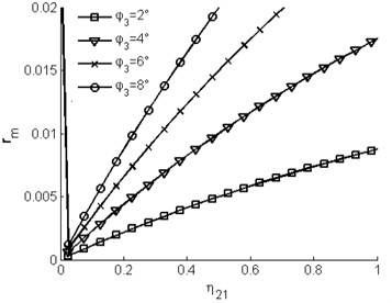
Fig. 2 shows the region of self-synchronization of the vibrating system in -plane for being 2°, 4°, 6° and 8°, respectively. Each curve partitions the -plane into two regions. Two non-identical rotors could operate self-synchronically when parameters and are in the region above the curves. On the contrary, if the parameters in the regions are beneath the curves, the self-synchronous of this vibrating system get more difficult. It can be seen that with increasing the value of the pivot angle , the region of self-synchronization gradually decreases in the -plane. So the displacement amplitude of the pendulum rod is an important parameter to determine if the vibrating system can implement the synchronous motion. By Eq. (13), the value of parameter is related to dimensionless parameters , and . Here and are proportional to , and is inversely proportional to . So in the following numerical simulation we take parameter as a constant (i.e. keeping the mass of the motors and platform invariable in the vibrating system) and investigate the influence of the self-synchronization of the two rotors with the change of parameters and .
Fig. 2Region of self-synchronization of the vibrating system
4.2. Numerical simulation
Further analyses have been performed by numerical simulations, which were carried out by applying the Runge-Kutta routine with adaptive stepsize control to the dynamics Eq. (8) of the proposed vibrating system. According to the analysis of the theory in section 3, we would suitably adjust the mass of rotor 2 () and the length of the pendulum rod (), this means that we could suitably change the value of dimensionless parameters and . Other stander parameters in the vibrating system are shown in Table 1. Meanwhile, we chose two identical induction motors to drive two unbalanced rotors, and the parameters of the motor are shown in Table 2, and the two motors are supplied with the electric source at the same time.
Table 1The parameters of the vibrating system
Parameters | Values |
The mass of vibrating system: (kg) | 150 |
The mass of rotor 1: (kg) | 3 |
The mass of rotor 2: (kg) | 3 |
The mass of the induction motor (kg) | 20 |
The eccentricity of unbalanced rotors (m) | 0.05 |
The length of the pendulum rod | 0.05 |
The stiffness coefficient of elastic element (N/m) | 63000 |
The damping coefficient of elastic element (N/(m/s)) | 270 |
The stiffness coefficient of torque spring (Nm/rad) | 500 |
The damping coefficient of torque spring (Nm/(rad/s)) | 5 |
Table 2The parameters of the motor
Parameters | Values |
Rated power (KW) | 0.7 |
Rated voltage (V) | 220 |
Rated frequency (Hz) | 50 |
Rated velocity (rad/s) | 157 |
Pole number | 2 |
Stator resistance () | 0.56 |
Rotor resistance () | 0.54 |
Stator inductance (H) | 0.1 |
Rotor inductance (H) | 0.12 |
Mutual inductance between stator and rotor (H) | 0.13 |
The damping coefficient of shafting (Nm/(rad/s)) | 0.01 |
4.2.1. Simulation result for ,
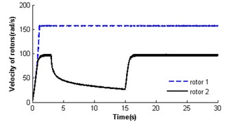
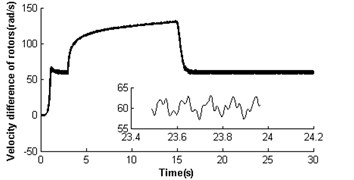
Fig. 3Absence of self-synchronization for η21=1 and rr=1 (m2=3, r3=0.05)
a)
b)
c)
d)
e)
f)
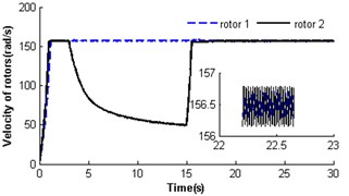
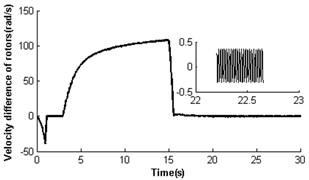
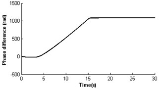
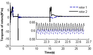
Fig. 3 illustrates the absence of self-synchronization for , . It can be seen that the velocities of rotors have different value. The velocity of rotor 2 is far less than its rated velocity in the whole operation process, and rotor 1 is close to the rated velocity of the motor (see Fig. 3(a)). Then the velocity difference approaches 60 rad/s (see Fig. 3(b)), and the rotor phase difference is and gradually increases (see Fig. 3(c)), i.e. the self-synchronization is absent. As the velocity of rotor 2 is lower than that of rotor 1, the electromagnetic torques on rotor 2 is larger than rotor 1 at time 15 s (see Fig. 3(d)); in this case, . The mutual coupling process between the pendulum rod and rotor 2 having nonlinear characteristics leads to their destabilized motion before 16 s (see Fig. 1(a) and (e)), and after that the pendulum rod is swing with a harmonic source. And the displacement amplitude of the pendulum rod is about 0.15 rad (8.59°). As the absence of self-synchronization, the motion of the platform is destabilized with a noperiodic vibration (see Fig. 3(f)).
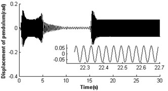
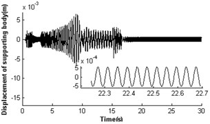
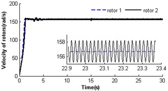
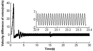
4.2.2. Simulation result for ,
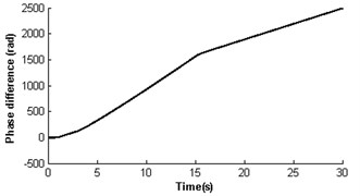
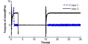
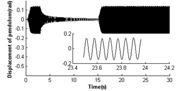
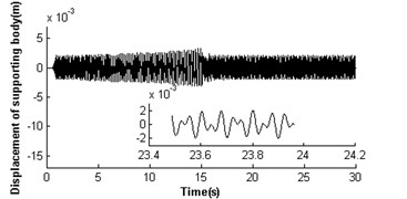
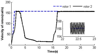
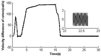
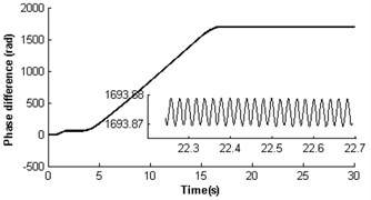
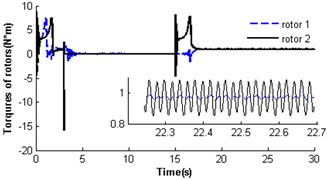
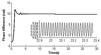
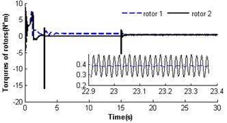
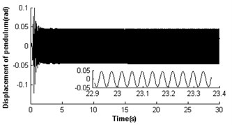
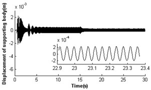
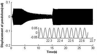
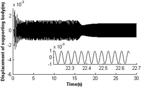
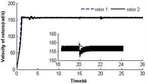
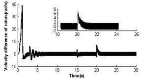
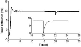
Fig. 4 shows the self-synchronization of the vibrating system when we take the eccentricity of unbalanced rotors as a constant and increase the length of the pendulum rod to two times that of section 3.2.1, i.e. and . The velocity of rotor 2 is far less than the rated velocity of motors in the start process as a stronger disturbance of the pendulum rod on the motor shaft, but the velocity of rotor 1 is close to the rated velocity of the motor (see Fig. 4(a)). In 17 s when the pendulum rod steadily and periodically swings (see Fig. 4(e)), the rotors operate with approximate velocity 156 rad/s called as synchronous velocity or synchronous speed. At this moment, the displacement amplitude of the pendulum rod is 0.069 rad (3.95°); the rotor velocity difference only approaches ±1.6 rad/s (see Fig. 4 (b)); the rotor phase difference begins to stabilize gradually at 1693.875 rad (269×2+1.18, see Fig. 4(c)). Omitting integral multiple of 2, the phase difference of the system synchronization could be rewritten as ; this is in accordance with the theoretical analysis in Section 3.2 And the synchronous process of the vibrating system is adjusted by transmission of electromagnetic torque between the two motors began at 15 s and ended at 17.5 s (see Fig. 4(d)). As the counteraction of the vibration force produced by two identical rotors, the platform with micro-vibration moves in cycles on the -direction (see Fig. 4(f)).
Fig. 4Self-synchronization for η21=1 and rr=0.5 (m2=3, r3=0.1)
a)
b)
c)
d)
e)
f)
4.2.3. Simulation result for ,
Fig. 5 shows self-synchronization of the vibrating system when we take the parameteras a constant and continually increase the length of the pendulum rod to three times of that in Section 4.2.1, i.e. and . The velocity of rotor 2 is also far less than the rated speed of the motor as the stronger disturbance of the pendulum rod on the motor shaft during the starting few seconds (at first 1.7 s). Then the two rotors synchronously rotate with velocity 157 rad/s, but still a weaker disturbance of the pendulum rod to the motor shaft still does not end until at 15 s (see Fig. 5(a)). At the moment, the rotor velocity difference approaches only ±1.7 rad/s (see Fig. 5(b)), and the rotor phase difference begins to stabilize gradually at 9.63 rad (, see Fig. 5(c)). Omitting integral multiple of 2, the phase difference of system synchronization could be rewritten as , which is also in accordance with the theoretical analysis in Section 3.2 (). The displacement amplitude of the pendulum rod is around 0.044 rad (2.52°, see Fig. 5(e)). The platform with micro-vibration also moves in cycles in the direction (see Fig. 5(f)). Comparing the simulation results with section 4.2.1 and 4.2.2, it can be seen that with the increase of the length of the pendulum rod, the pivot angle becoming smaller is in favour of the self-synchronization implementation of the two rotors. So the larger displacement amplitude of the pendulum rod leads to a stronger disturbance to the synchronous velocity of rotor 2.
Fig. 5Self-synchronization for η21=1 and rr=0.3 (m2=3, r3=0.15)
a)
b)
c)
d)
e)
f)
4.2.4. Simulation result for ,
In section 4.2.1, the two identical rotors cannot operate synchronously with such parameters , . Nevertheless, theoretical analysis having displayed parameter is also another key parameter to influence the synchronization of the vibrating system. Here, the simulation results would be given when dimensionless parameter was decreased to 0.3 (i.e. keeping the mass of rotor 1 invariable and reducing the mass of rotor 2 to one-third of that in Section 4.2.1). Fig. 6 shows self-synchronization of the vibrating system for and . The variation tendency of the velocity and torque of the rotors are similar to Fig. 4. When the system operates synchronously and steadily, the synchronous speed of the rotors is around 156.5 rad/s; the velocity difference of the rotors is around ±0.4 rad/s; the rotor phase difference is around 1085.1 rad (i.e. ); displacement amplitude of the pendulum rod is around 0.054 rad (3.09°). Comparing Fig. 3-6, it can be seen that the self-synchronization of the two rotors are implemented in the system whose displacement amplitude of the pendulum rod is smaller. And the values of dimensionless parameters and determine the value of the phase difference of the rotors.
Fig. 6Self-synchronization for η21=0.3 and rr=1 (m2=2, r3=0.05)
a)
b)
c)
d)
e)
f)
4.2.5. Simulation results for , with a disturbance
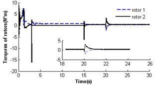
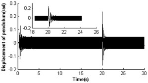
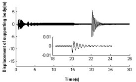
To further verify the self-synchronous stability of the rotors, it is necessary to perform simulations for the vibrating system with a phase disturbance on the rotor, and the results are shown in Fig. 7. Here, a disturbance of phase is added to the motor 2 at 20 s. The driving torques that the coupling toques act on the motor 1 becomes the load torques. Oppositely, the load torques on motor 2 becomes the driving torques (see Fig. 7(d)). This phenomenon leads to decrease of the velocity of rotor 2 and the increase of the velocity of rotor 1 (see Fig. 7(a)). With the self-adjustment of the coupling torque, the disturbed vibrating system gradually returns to the previous steady state. In the above process of disturbance added, the displacements of the pendulum rod and the platform have the large value as the phase difference changes. However, throughout the numerical simulation, no matter how much and when the disturbance is, the synchronization of the two rotors still continues. If a disturbance of phase is added to motor 1, the disturbed vibrating system could also return to previous steady state. Here, we don’t give a detail discussion as the numerical result is similar to Fig. 7.
Fig. 7Self-synchronization for η21=1 and rr=0.3 with a disturbance
a)
b)
c)
d)
e)
f)
5. Conclusions
The vibrating system we proposed in this paper could be used to design new balanced elliptical vibrating screens when their structure parameters satisfy the self-synchronization criterion and synchronous stability condition. For the development in the early stage and clearly understand the self-synchronization criterion and synchronous stability, we investigate the system considering only the platform with the vertical displacement (actually horizontal displacement of the platform is neglected) because of the complex nonlinear of the dynamics system, but the simplified model wouldn’t loss itself natural properties (see Ref. [4] and [6]). In the future research (considering multiple DOFs of the platform) will be needed. With the theoretical investigation and numerical simulation, the following conclusions are obtained.
Base on the average method and revisionary small parameters, the self-synchronization equation of the vibrating system is deuced. The criterion of implantation synchronization for two rotors is also derived, and that of stability of synchronous state is judged by the Routh-Hurwitz criterion. The theoretical results show that the displacement of the pendulum rod and dimensionless parameter directly determine whether the two rotors in the system can implement the synchronous motion. We find that the overlarge value of parameters and may lead to absence of self-synchronization. This means that a small value of parameters and is beneficial to the implementation of self-synchronization of this vibrating system.
Then, we employ numeric simulations to verify the correctness of theoretical investigation. So the regions and process of self-synchronization of the vibrating system are numerically ascertained. From the regions of the self-synchronization of the system (see Fig. 2), it can be seen that increasing the value of parameters and the possibility of self-synchronization implementation gradually decrease. This is corresponding the theoretical investigation. The processes of system self-synchronization with different values of parameters and is displayed in Figs. 3-7, respectively. By comparing these results of numerical simulation, it can also be seen that smaller values of parameters and are in favor of the self-synchronization of the system. In sum, in order to obtain the steady self-synchronization of two rotors in the vibrating system, we could increase the length of the pendulum rod or decrease the mass of the rotor connected with the pendulum rod.
References
-
Hugenii C. Horologium Oscilatorium. Paris, France, 1673.
-
Rayleigh J. Theory of Sound. Dover, New York, 1945.
-
Van der Pol B. Theory of the amplitude of free and forced triode vibration. Radio Review, Vol. 1, 1920, p. 701-710.
-
Blekhman I. I. Synchronization in Science and Technology. ASME press, New York, 1988.
-
Blekhman I. I. Selected Topic in Vibrational Mechanics. World scientific, Singapore, 2004.
-
Blekhman I. I., Fradkov A. L., Nijmeijier H., Pogromsky A. Y. Self-Synchronization and controlled synchronization. System and Control Letters, Vol. 31, 1997, p. 299-305.
-
Blekhman I. I., Fradkov A. L., etc. Self-Synchronization and controlled synchronization: general definition and example design. Mathematics and Computers in Simulation, Vol. 58, 2002, p. 367-384.
-
Wen B. C., Fan J., etc. Vibratory synchronization and controlled synchronization in engineering. Science press, Beijing, 2009.
-
Zhao C. Y., Zhang Y. M., Wen B. C. Synchronization and general dynamic symmetry of a vibrating system with two exciters rotating in opposite directions. Chinese Physics B, Vol. 19. Issue 3, 2010.
-
Zhao C. Y., Zhu H. T., Wang R. Z., Wen B. C. Synchronization of two non-identical coupled exciters in a non-resonant vibrating system of linear motion, Part I: Theoretical analysis. Shock and Vibration, Vol. 16, Issue 5, 2009, p. 505-516.
-
Zhao C. Y., Zhu H. T., Wang R. Z., Wen B. C. Synchronization of two non-identical coupled exciters in a non-resonant vibrating system of linear motion, Part II: Theoretical analysis. Shock and Vibration, Vol. 16, Issue 5, 2009, p. 517-528.
-
Zhang X. L., Zhao C. Y., Wen B. C. Theoretical and experimental study on synchronization of the two homodromy exciters in a non-resonant vibrating system. Shock and Vibration, Vol. 20, 2013, p. 327-340.
-
Zhang X. L., Zhao C. Y., Wen B. C. Synchronization of three non-identical coupled exciters with the same directions in a far-resonant vibrating system. Journal of Sound and Vibration, Vol. 332, 2013, p. 2300-2317.
-
Zhang X. L., Zhao C. Y., Wen B. C. Vibratory synchronization and coupling dynamic characteristics of multiple unbalanced rotor on a mass-spring rigid base. International Journal of No-Linear Mechanics, Vol. 60, 2014, p. 1-8.
-
Balthazar J. M., Palacios J. L., Reyolando M. B. Short comment on self-synchronization of two non-ideal source supported by a flexible portal frame structure. Journal of Vibration and Control, Vol. 10, 2004, p. 1739-1748.
-
Balthazar J. M., Palacios J. L., Reyolando M. B. Some comment on numerical simulation self-synchronization of four non-ideal exciters. Applied mathematics and computation, Vol. 164, 2005, p. 615-625.
-
Bennett M., Schatz M. F., Rockwood H., Wiesenfeld K. Huygens’ clocks. Proceedings Royal Society: A, Vol. 458, 2002, p. 563-580.
-
Senator M. Synchronization of two coupled escapement-driven pendulum clocks. Journal of Sound and Vibration, Vol. 291, 2006, p. 566-603.
-
Pena Ramirez J., Fey R. H. B., Nijmeijer H. In-phase and anti-phase synchronization of oscillators with Huygens’ coupling. Cybernetics and Physics, Vol. 1, Issue 1, 2012, p. 58-66.
-
Kapitaniak M., Czolczynski K., et al. Synchronous states of slowly rotating pendula. Physics Reports, 2014.
-
Koluda P., Perlikowski P., Czolczynski K., Kapitaniak T. Synchronization configurations of two coupled double pendula. Communications in Nonlinear Science and Numerical Simulation, Vol. 19, 2014, p. 977-990.
About this article

This study is supported by National Natural Science Foundation of China (Grant No. 51074132).
