Abstract
A vibrational dynamic system is considered, designed for effective reduction of solid materials. Two system arrangements are presented. Using the results of the theory of synchronization of mechanical vibrators, formulas are obtained for assessing the steadiness and stability of self-synchronization of the unbalanced vibrators in the vibrational systems under consideration. The calculation results for the formulas obtained enable the selection of the most efficient and reliable structural arrangement for the vibrational dynamic system.
1. Introduction
In most industries involving crushing and grinding of natural and technical solid materials, it is critical for the reduction to occur along the intergrowth surfaces of the crystals. This type of disintegration allows increasing the recovery of valuable components during subsequent ore processing and, for a number of materials, also significantly improves the processing properties associated with the shape and surface profiles of the crushed grains.
In present-day industry, cone crushers with eccentric drive of the crushing head are most widely used for the reduction of solid materials. However, these crushing machines do not provide the best conditions for the reduction of materials in the intercrystalline zones. Pieces of material in the crushing chamber are subjected to force impacts only from the working surfaces of the crushing bodies. The lack of force interaction between the pieces and the indefinite nature of the forces arising from the reduction of such pieces are not beneficial for the crushing selectivity and do not prevent the destruction of crystals. In addition, due to their specific kinematic features, cone crushers with eccentric drives have low reduction ratios and are prone to drive failures caused by pieces of uncrushable materials entering the crushing chamber.
In view of the foregoing, the task of increasing the selectivity of crystal liberation and the reduction ratio in the disintegration of solid materials is one of the most important problems in mineral processing and in the processing of technogenic raw materials [1, 2].
One of the possible solutions to this problem consists in the creation of vibratory dynamic systems with advanced energy characteristics of oscillation excitation that would generate vibration effects on the material processed with the best processing profiles [3-6]. A vibratory cone crusher represents such a dynamic system. The use of unbalanced vibrators instead of an eccentric to drive the crushing bodies allows a transition from the crushing principle with the given material deformation to the crushing principle with the given force. In addition, the inertia drive makes it possible to significantly increase the oscillation frequency of crushing bodies and the crushing force, which is especially significant when reducing solid materials. The power and kinematic features of a vibratory cone crusher that ensure comprehensive loading of the material being processed also predetermine the high selectivity of crystal liberation and the high reduction ratios with the minimum recovery of fines in the material crushed. In addition, this crusher has a significant operational advantage: it prevents drive failures commonly occurring when unbreakable material pieces enter the crushing chamber. Therefore, a vibratory cone crusher may be used to implement the principles of streamlined material reduction to the fullest extent and to obtain a number of significant processing advantages.
2. Schematic diagrams for a vibrational dynamic system
Let us consider two different schematic diagrams for a vibratory cone crusher [7, 8], as shown in Fig. 1, 2. In these diagrams, based on the use of two unbalanced vibrators without kinematic coupling as vibration exciters, their synchronous and in-phase rotation is ensured due to the phenomenon of self-synchronization. The main difference is that, in the first case, flat (vertical) oscillations of the working bodies are excited and, in the second case, three-dimensional (helical) oscillations are generated. The three-dimensional form of oscillations is obtained by adjusting the inclination angle of the axes of the vibrator rotors in the vertical plane.
Fig. 1Schematic diagram of a vibratory cone crusher with flat oscillations of the working bodies
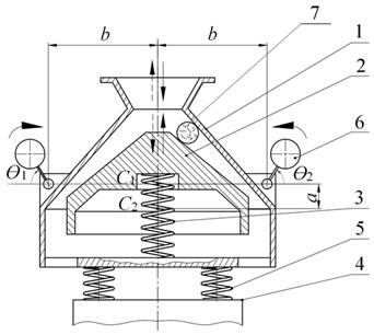
Fig. 2Schematic diagram of a vibratory cone crusher with three-dimensional oscillations of the working bodies
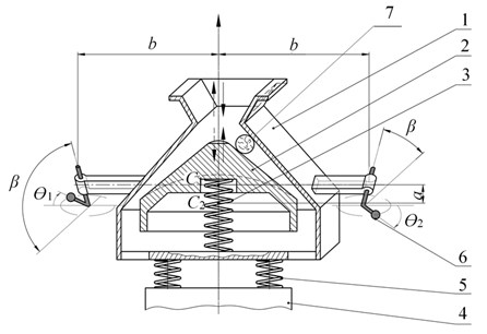
The crusher (Fig. 1, 2) contains a shell 1 and a head 2 that is connected to the shell 1 with the use of special packages of coil springs 3. The shell 1 and the head 2 may be regarded as absolutely rigid bodies. The working surfaces of the shell 1 and the head 2 form the crushing chamber. The shell 1 is fixed on the fixed support 4 using elastic shock absorbers 5. The unbalanced vibrators 6 are located in the shell 1 symmetrically relative to the vertical axis of symmetry of the machine and represent unbalanced rotors, rotated by two independent induction motors [9]. In the crusher shown in Fig. 2, the axes of the rotors of the vibrators 6 are inclined in the vertical plane in opposite directions at the angle of to the horizontal plane.
A vibratory cone crusher operates as follows. In the operating mode, the rotors of the same unbalanced vibrators 6 rotate synchronously with the same frequency and in the same phase, which generates strictly vertical (Fig. 1) or helical (Fig. 2) counter-oscillations of the shell 1 and the head 2. The feed material 7, entering from above into the crushing chamber formed by the working surfaces of the shell 1 and the head 2, is reduced under the counter-oscillations of the shell 1 and the head 2; the crushed material is discharged from the bottom during the return stroke of the shell 1 and the head 2.
3. Evaluation of steadiness and stability of self-synchronization of unbalanced vibrators in a vibrational dynamic system
When selecting the vibratory cone crusher design with the best dynamics performance, it shall be assumed that efficiency and reliability of the machine are achieved through the steady and stable synchronous and in-phase rotation of its unbalanced vibrators. This regime always exists in symmetric vibration machines with two self-synchronizing vibrators. Forced oscillations of the shell and the head in this regime are vertical (Fig. 1) or helical (Fig. 2) and occur in phase opposition.
The steadiness of synchronous rotation of the vibrators at idle shall be assessed by the value of the dimensionless steadiness factor [10]. Recall that, for steadiness, this dimensionless coefficient must be positive. Moreover, its higher values correspond to greater steadiness margins. For the crusher under consideration, the expression for this coefficient is [11]:
Here, , are the masses of the shell and the head, respectively, kg; is the reduced mass of the two-mass system under consideration, kg; is the synchronous angular velocity of the vibrators, s-1; is the shortest horizontal distance between the rotor axis of the unbalanced vibrator and the center of mass of the shell, m; is the shortest vertical distance between the common center of mass of the crusher and the center of mass of the shell in the static equilibrium position of the machine, m; is the shortest vertical distance between the centers of mass of the shell and the head of the machine, m; , are the central moments of inertia of the shell and the head about the vertical axis, kg∙m2; , are the central moments of inertia of the shell and the head about the axis perpendicular to the vertical plane of oscillation, kg∙m2; , are the natural frequencies of free vertical and rotary (in the horizontal plane) oscillations of the two-mass system under consideration, s-1; is the inclination angle of the axes of the rotors of the vibrators to the horizontal plane, deg.
Note that the value of angle 0 corresponds to the flat arrangement of the crusher (Fig. 1).
In order to assess the phasing stability of self-synchronizing vibrators at idle, the following approximate formula [12] is used:
where is the dimensionless coefficient, referred to as the coefficient of vibration coupling; is the greatest value of the vibratory moment exerted on the rotor of one of the vibrators by the other vibrator, Nm; is the rated torque of the motor, Nm.
For the crusher under consideration, the expression for the vibration coupling coefficient is:
Here, is the mass of the unbalanced load of the vibrator, kg.
Recall that, for stability, the condition below must be met:
where is the minimum acceptable value of the coefficient . According to the gradation of the relative strength of the vibration coupling between the vibrators mounted on a movable base, self-synchronization may be expected when 0,3 [12].
4. Selection of the best vibrational dynamic system design
The baseline data for assessing the steadiness of synchronous rotation and the phasing stability of self-synchronizing unbalanced vibrators in a vibratory cone crusher are given in Table 1.
Table 1Parameters of vibratory cone crusher
Name | Meas. units | Designation | Value |
Shell weight (including 2 ) | kg | 27.2 | |
Head weight | kg | 8.65 | |
Unbalanced vibrator weight | kg | 1.78 | |
Central moment of inertia of the shell (relative to the axis perpendicular to the vertical plane of oscillation) | kg m2 | 0.511 | |
Central moment of inertia of the head (relative to the axis perpendicular to the vertical plane of oscillation) | kg m2 | 0.03 | |
Central moment of inertia of the shell (relative to the vertical axis) | kg m2 | 0.591 | |
Central moment of inertia of the head (relative to the vertical axis) | kg m2 | 0.043 | |
Tensile and compression rigidity of coil spring packages connecting the shell and the head | N/m | 74460 | |
Torsional rigidity of coil spring packages connecting the shell and the head | Nm/rad | 29784 | |
Vibrator eccentricity | m | 0.026 | |
Distance from the vertical axis of symmetry of the machine to the vibrator rotor axis | m | 0.170 | |
Vertical distance from the common center of mass of the machine to the center of mass of the shell (considering the sign) | m | 0.015 | |
Vertical distance between the centers of mass of the shell and the head of the machine (considering the sign) | m | 0.058 | |
Inclination angle of the axes of the vibrator rotors to the horizontal plane | degr. | 0, 15, 30, 45 | |
Synchronous angular speed of the vibrators | с-1 | 157 | |
Rated motor torque | N/m | 1.73 |
The steadiness and stability of self-synchronization of unbalanced vibrators in a vibrating cone crusher of two different arrangements, as shown in Fig. 1, 2, are assessed using Eq. (1) and Eq. (3), and the data in Table 1. The results of the evaluation are presented in the form of graphs for the dependencies of steadiness coefficients and the vibration coupling on the angle of inclination of the axes of the vibrator rotors to the horizontal plane (Fig. 3).
Fig. 3Steadiness coefficients α and vibration coupling kω vs inclination angle β of the axes of the vibrator rotors to the horizontal plane
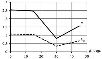
It may be seen in the graphs that the dimensionless steadiness coefficient is positive in the range of variation of the angle from 0° up to 45°, which indicates steady synchronous rotation of the vibrators at these values of . The value of this coefficient is the greatest when 0°. For the dimensionless vibration coupling coefficient , at 0°, Eq. (4) is the strongest. In this case, the relative strength of the vibration coupling between the vibrators is very high and self-synchronization and the accompanying phenomena are highly probable.
5. Conclusions
The paper considers two different concepts of a vibratory cone crusher, in which the principles of streamlined reduction of solid materials are implemented to the fullest extent. The theoretical study performed allows estimating the influence of the angle of inclination of the rotor axes of unbalanced vibrators to the horizontal plane on the steadiness and stability of synchronous and in-phase rotation of these vibrators in the crusher under consideration. It is found that, with the same machine parameters, an increase in the inclination angle of the rotor axes of the vibrators negatively affects the steadiness of synchronous rotation and the phasing stability of the self-synchronizing vibrators.
It may therefore be concluded that a vibratory cone crusher with flat oscillations of the working bodies is more preferable from the point of view of steadiness and stability and, consequently, is more efficient and reliable in operation than a crusher with three-dimensional oscillations of the working bodies.
References
-
Chanturiya V., Vaisberg L., Kozlov A. Promising trends in investigations aimed at all-round utilization of mineral raw materials. Journal of Obogashchenie Rud, Vol. 2, 2014, p. 3-9.
-
Revnivtsev V. On the rational organization of minerals release in accordance with modern outlooks of solid state physics. Journal of Upgrading and Development of the Process of Ore Preparation for Beneficiation, Vol. 140, 1975, p. 153-169.
-
Vaisberg L., Zarogatsky L., Turkin V. Vibratory Crushers. Basics of Calculation, Design and Technological Application. VSEGEI, St. Petersburg, 2004.
-
Vaisberg L., Zarogatsky L. New generation of jaw and cone crushers. Journal of Building and Road Construction Machinery, Vol. 7, 2000, p. 16-21.
-
Vibrations in Technique: a Handbook. Vibrating Processes and Machines, Vol. 4, Mashinostroyeniye, Moscow, 1981.
-
Blekhman I. Theory of Vibrational Processes and Devices. Vibrational Mechanics and Vibration Technics. Ore and Metals, St. Petersburg, 2013.
-
Pat. 169545, Russian Federation.
-
Pat. 2292241, Russian Federation.
-
Dresig H., Fidlin A. Schwingungen mechanischer Antriebssysteme: Modellbildung, Berechnung, Analyse, Synthese. Springer, Berlin, Heidelberg, 2014.
-
Blekhman I. Synchronization of Dynamical Systems. Nauka, Moscow, 1971.
-
Safronov A., Kazakov S., Shishkin E. Synchronization of inertia vibroexciters in vibratory-impact cone crusher with three-dimensional motions of working members. Journal of Obogashchenie Rud, Vol. 4, 2012, p. 43-47.
-
Blekhman I. Vibrational Mechanics and Vibrational Rheology (Theory and Applications). Fizmatlit, Moscow, 2018.
About this article

Financial support was provided by the Russian Science Foundation No. 17-79-30056 (Project REC “Mekhanobr-tekhnika”).
