Abstract
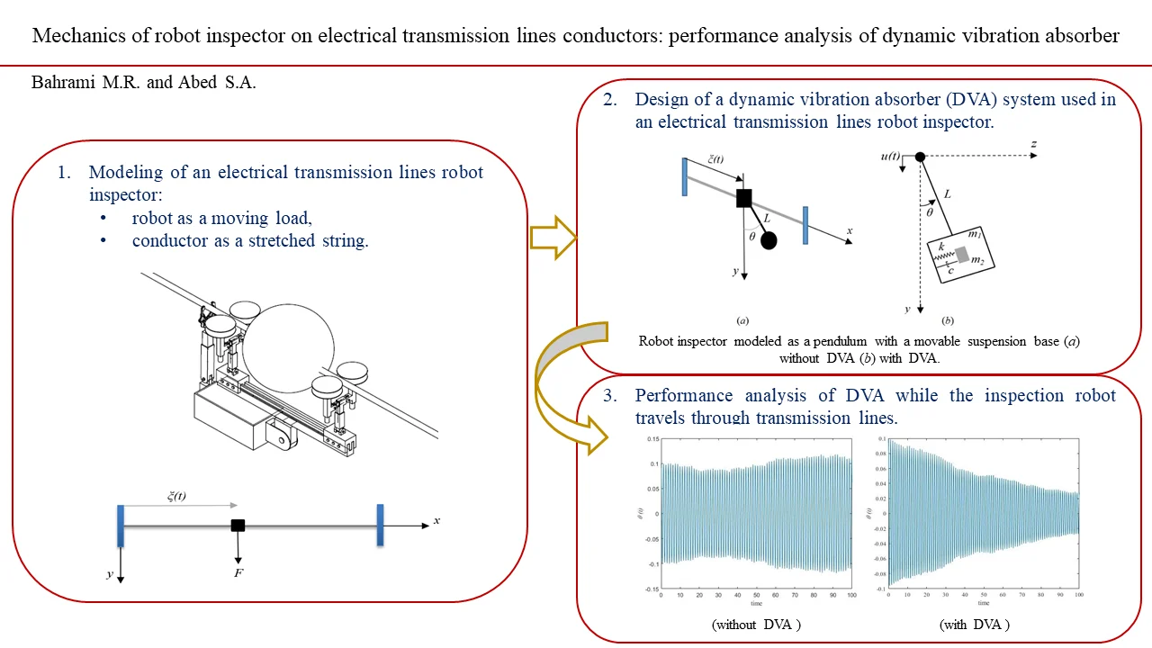
The aim of this paper is to create a mathematical model of the movement of electrical transmission lines inspection robot while moving on the line. In this model, the electrical line is considered as a stretched string while the robot considered as a moving load on the line. The obtained equation of motion has been solved by using the Lagrange equation. Even the motion of the inspection robot on the line is steady, but dangerous vibrations in the vertical plane of the motion have been observed. These types of oscillation may cause parametric oscillations in the perpendicular plane since the robot-inspector considered as moving load and pendulum. To achieve dynamical stability during the movement of inspection robot on the electrical line and avoid dangerous oscillation, dynamic vibration absorber has been designed. Then the performance of dynamic vibration absorber has been investigated.
Highlights
- Modeling of a robot inspector while traveling on an electrical transmission lines.
- Vibration of the stretched string.
- Design of a dynamic vibration absorber system used in an electrical transmission lines robot inspector.
- Performance analysis of DVA used in a pendulum with a movable suspension.
1. Introduction
Regular inspection are needed for overhead electrical transmission lines during the year. Inspection is needed to decrease the cost of repair. In some countries for autonomous inspecting the overhead electrical transmission lines robots are used [1]. The idea of using robot inspector for overhead electrical transmission lines is to reduce human exposure in a potentially dangerous environment while gathering the required data to understand the condition of components of the electrical lines (conductors, isolators, etc.).
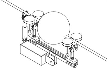
Electrical line inspection robots vary for different tasks [2-6]. Fig. 1 illustrates one of the proposed overhead electrical transmission lines robot inspector [7]. This robot is able to pass through the different types of obstacles of electrical transmission lines such as dampers, clamps, warning balls. Operating experience and research [2-6] show that even the robot inspector moves steadily along the line, excessive intensity fluctuations can appear. These oscillations act as considerable inertia loads on robot construction and lead to robot failure.
Fig. 1Scheme of the electrical transmission inspection robot while passing the warning ball
Therefore, a mathematical model of robot inspector motion along the conductor is needed to understand the essence of these fluctuations [8-10].
The purpose of this article is to develop a new mathematical model to analysis the electrical transmission lines inspection robot movement on the line. Here, the conductor is considered as a stretched string and the robot as a load which is moving along the line. In the last section of this work a dynamic vibration absorber system has been designed to prevent parametric type fluctuation in the perpendicular plane of motion.
2. Vibration of the stretched string
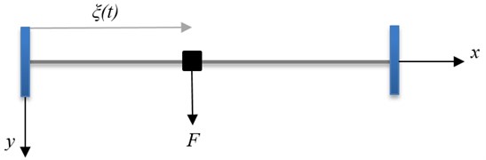
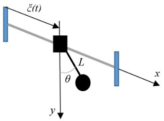
Fig. 2 shows the model in which the conductor is considered as a stretched string, and the robot inspector is considered as a moving load.
Fig. 2Stretched string with a moving load
The string deflection equation, , is given from [11]:
with boundary and initial conditions of 0, 0. Here, is designated to the string tension force, denotes to the linear load (per unit length), is the density, is the string length. Differentiation relative to the coordinate and time showed by prime and dot.
The force concentrated at a point using delta function will be:
The loading point can move according to an arbitrary law with the condition of , 0,
The solution to the problem Eq. (1) can be constructed by the method of Lagrange equations (2nd order):
The kinetic energy of a system represented as a function of generalized coordinates, velocities, and time. Potential energy designated by represented the function of general coordinates and time. Generalized forces, , are determined from the expression of the virtual work of those forces that are not associated with the potential energy,
The kinematic and potential energies of the string are:
By setting the approximate solution , we will get:
Rewriting to the discrete model leads to an ODE system:
and solved by computer mathematics (Mathcad, Radau) [12]. Fig. 3(a) and (b) show the deflection and acceleration of the conductor. The following parameters have been used for calculation: 10 kN, 1 kN, 2 m/s, 5 kg/m, 200 m. In Fig. 3(a) saw-tooth oscillations appear in the vertical plane even the movement of the load is steady. Acceleration, , showed in Fig. 3(b) cause inertial load on the construction of the robot.
Fig. 3a) Conductor deflection, b) acceleration
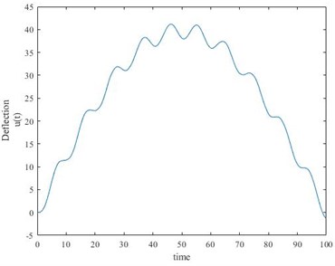
a)
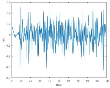
b)
3. Dynamic vibration absorber system usage in electrical transmission lines robot inspector
In this section, a robot considered as a pendulum with a movable suspension base shown in Fig. 4(a). As the consequence of the oscillations in the vertical plane of motion parametric oscillations might appear. To prevent dangerous oscillation in the perpendicular plane of motion (- plane) proposed using dynamic vibration absorber (DVA). Fig. 4(b) shows the schematic of the dynamic vibration absorber DVA to reduce the sway motion of a pendulum (robot considered as a pendulum) with a suspension base.
Fig. 4Pendulum with a movable suspension base: a) without DVA, b) with DVA
a)
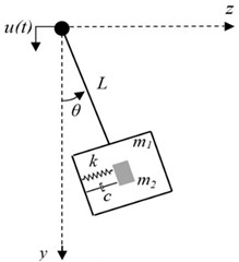
b)
The pendulum mass (robot mass) is designated by . is the deflection angle measured in the - plane from the vertical axis. is the length of the pendulum. is the moment of inertia about the axis of suspension. The tuned mass locates in the static position. and are the spring stiffness and the damping coefficient of the DVA system. Function describes the base motion in the vertical direction, found in section 2.
3.1. Pendulum with a movable suspension base
To better understanding of the performance of DVA while the inspection robot travels through transmission lines, first we study the case (pendulum with a movable suspension base) showed in Fig. 4(a). The equation of a pendulum with a movable suspension has been used:
Setting 0.1, 0 and as shown in Fig. 3(b), numerical solution of Eq. (6) obtaining by Mathcad has been shown in Fig. 5(a) using the following parameters: 100 kg, 10 kg, 0.3 m, 3.068×10⁻⁷ kg m2, 9.98 m/s2.
3.2. Pendulum with a movable suspension base with a dynamic vibration absorber system
The equation of motion for the system shown in Fig. 4(b), one can be obtained by the method of Lagrange equations (2nd order). The twice of the kinetic energy can be written as:
The potential energy is given by:
After completing all the necessary actions in accordance with the Lagrange equation (second order), knowing the general force in the direction of the general coordinate , , one can obtain the system of equations:
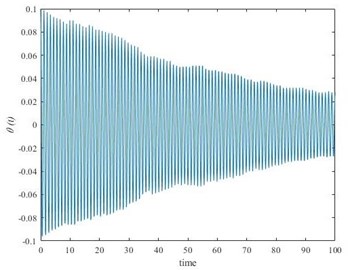
Study of this character can be done by mathematical modeling by setting 0.1, 0 and as shown in Fig. 3(b). Numerical solution of Eq. (9) been obtained using Mathcad. Fig. 5(b) shows the result using the parameters as in the section 3.1 and setting 0.1 N/m, 3 N.s/m.
In the case, pendulum with a movable suspension base, one can observe the increase of the amplitude of fluctuations in the perpendicular plane of motion from Fig. 5(a). The saw-tooth fluctuations in vertical plane caused the parametric oscillation in the perpendicular plane. This case shows the possibility of dangerous oscillations (parametric). On the other hand, as shown in Fig. 5(b) the amplitude of fluctuations decreased by the time of the process using DVA in the robot inspector construction. This example shows the possibility of usage of DVA in electrical transmission inspection robots.
Fig. 5Performance analysis of DVA used in a pendulum with a movable suspension: a) without DVA, b) with DVA
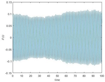
a)
b)
4. Conclusions
The dynamical behavior of the electrical transmission lines inspection robot motion traveling through the line has been studied. Mathematical modeling shows that even the motion of the inspection robot on the line is steady, but dangerous vibrations in the vertical plane of the motion appear. This oscillation can cause parametric type vibrations in the perpendicular plane. To achieve dynamical stability during the movement of inspection robot on the electrical line and to avoid dangerous oscillation in the horizontal plane, dynamic vibration absorber has been designed and studied. The result shows a reduction of the amplitude of fluctuations in the perpendicular plane of motion which shows the possibility of usage of DVA in electrical transmission inspection robots. Practical results can be useful for engineers to select proper parameters and speed during the design stage.
References
-
Toussaint K., Pouliot N., Montambault S. Transmission line maintenance robots capable of crossing obstacles: State‐of‐the‐art review and challenges ahead. Journal of Field Robotics, Vol. 26, Issue 5, 2009, p. 477-499.
-
Aoshima S. I., Tsujimura T., Yabuta T. A wire mobile robot with multi-unit structure. IEEE/RSJ International Workshop on Intelligent Robots and Systems, The Autonomous Mobile Robots and Its Applications, Vol. 4, 1989, p. 414-421.
-
Sawada J., Kusumoto K., Maikawa Y., Munakata T., Ishikawa Y. A mobile robot for inspection of power transmission lines. IEEE Transactions on Power Delivery, Vol. 6, Issue 1, 1991, p. 309-315.
-
Higuchi M., Maeda Y., Tsutani S., Hagihara S. Development of a mobile inspection robot for power transmission lines. Journal of the Robotics Society of Japan, Vol. 15, Issues 9-4, 1991, p. 457-463.
-
Tsujimura T., Morimitsu T. Dynamics of mobile legs suspended from wire. Robotics and Autonomous Systems, Vol. 20, Issues 1, 1997, p. 85-98.
-
Montambault S., Pouliot N. Design and validation of a mobile robot for power line inspection and maintenance. 6th International Conference on Field and Service Robotics-FSR, 2007.
-
Bahrami M. R. A novel design of an electrical transmission line inspection machine. Advances in Mechanical Engineering, 2016, p. 67-73.
-
Eliseev V. V., Bahrami M. R. Strength suspension of inspector robot on the electrical transmission line wire. Bulletin of Engineering, Vol. 6, 2016, p. 19-22.
-
Bahrami M. R. Mechanics of diagnostic machine on electrical transmission lines conductors. International Conference on Modern Trends in Manufacturing Technologies and Equipment, Vol. 224, 2018, p. 02021.
-
Eliseev V. V. Mechanics of Deformation of Rigid Body. Polytechnic University, St. Petersburg, Russia, 2006.
-
Tikhonov A. N., Samarsky A. A. Equations of Mathematical Physics. Science, Moscow, 1979.
-
Kiryanov D. V. Mathcad 14. BHV-Petersburg, St. Petersburg, 2007.
Cited by
About this article

