Abstract
Power equipment shows obvious low frequency line spectrum noise characteristics due to the power frequency. The effective noise control of the power equipment can be achieved by installing dynamic vibration absorbers (DVAs) on the structure surface of electrical equipment. However, if DVAs are not installed properly, considering the cases that they are installed at the vibration mode node position, the low radiation vibration mode and the redistribution of the integrate vibration power, the vibration and noise absorbing performances of DVAs may degrade. In order to achieve efficient vibration absorption and noise reduction on the power equipment, this paper proposes a low-frequency noise reduction technology for power equipment based on DVAs. The position optimization of the DAVs using in the power equipment is studied for the first time. Aimed at the single frequency radiated sound power of equipment, the integrate radiated sound power of the equipment is minimized through adjusting the position parameters of DVAs. A numerical case is studied to verify the effectiveness of the proposed DVAs position optimization. The results show that the noise control effect of the power equipment with the optimized DVAs is significantly improved. The method proposed in this paper solves the noise problem of the power equipment, which provides reference for power noise control.
Highlights
- The position optimization of the DAVs using in the power equipment is studied for the first time.
- Aimed at the single frequency radiated sound power of equipment, the integrate radiated sound power of the equipment is minimized through adjusting the position parameters of DVAs.
- The low frequency line spectrum noise control technology of power equipment based on optimal position strategy can compensate for the installation coupling effect to a certain extent.
1. Introduction
The power noise in power transmission and transformation project obviously shows low frequency line spectrum characteristics. The residents are getting annoyed with the noise pollution of the power equipment with the progress of urbanization. More attention is paid to the noise emitted by power equipment. The demand for noise control in power equipment has increased dramatically. Dynamic vibration absorber is mainly applicable to low frequency steady line spectrum vibration and noise reduction. Noise control of the power equipment based on DVAs has a very broad application prospect. As an efficient low frequency line spectrum noise control technology, DVAs have been applied in many engineering fields such as automobiles [1], high-speed railways [2], buildings [3], ships [4], aviation [5] and aerospace [6].
The application of the DVAs technology in power system is very few to be seen. Reza [7] designed a new type of DVA to reduce the vibration of power transmission line. This research shows the possibility of usage of the double pendulum as the DVA in electrical transmission. Hill [8] designed an adaptive DVA to reduce electrical transformer structural vibration. The research effectively gives the combination of a passive and active device, which leads to far greater stability and robustness. Cao [9] proposed a method for reducing vibration and noise of 10kV transformer based on distributed DVAs. The research realizes the obvious suppression of the vibration of the transformer shell. The radiated noise is effectively controlled based on the vibration reduction. In the previous application research of the vibration and noise attenuation of the power equipment, the author found that the action frequency of DVAs was shifted after coupling with the power equipment. The research on optimization of the low frequency noise control of the power equipment has been carried out to solve this problem. The research mainly optimized the frequency of DVAs by adjusting its parameters to minimize the acoustic index. The frequency optimization of DVAs improves the noise reduction effect of the DVAs and finally realizes the efficient noise control of power equipment [7]. However, during the further researtches, the author found the sound radiation of the power equipment will be enhanced when DVAs are installed in the wrong position. Therefore, the position optimization of DVAs is of great importance and should be highly concerned.
In this paper, a method for position optimization of DVAs in the noise reduction of power equipment is proposed novelly. An analogous transformer model of “oil-steel-air” is established to analyze the noise reduction effect of the designed DVA. The position optimization method of DVAs is proposed based on Nelder-Mead optimization algorithm. A finite element simulation example is used to compare the radiated sound power of the power equipment before and after position optimization. The comparison results verify the superiority of the position optimization of DVAs.
2. Problem formulation
Power equipment, which is shown in Fig. 1(a) (photted in Baoji of China in June 24 of 2020), is affected by AC power frequency, and its radiated noise shows obvious low-frequency line spectrum characteristics. The sound insulation and absorption technologies currently used in engineering can achieve good noise reduction effect in the high-frequency range. However, the low frequency noise control effect of these technologies is poor. To solve this low frequency noise problem, the DVAs are designed to achieve efficient noise control of the power equipment, which is shown in Fig. 1(b) (the structure of a DVA designed by State Grid Shaanxi Electric Power Research Institute in 2021). The acoustic radiation of the power equipment shows a dipole like low radiation mode at certain modal frequencies. The traditional DVAs may destroy the low radiation characteristics of the power equipment, which lead to poor noise reduction effect and even increase sound radiation. To solve this problem, the position optimization method of the DVAs is proposed based on the idea that the position movement of the DVAs change the low radiation mode at some specific frequencies.
Fig. 1Structural diagram of power equipment and the designed DVA
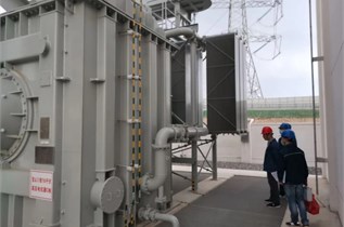
a) Power equipment
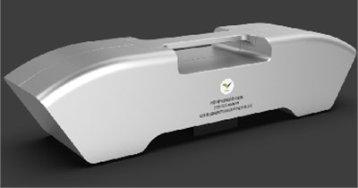
b) The designed DVA
3. Noise reduction mechanism of DVA
Fig. 2 shows the simplified forced vibration main system with dynamic vibration absorber (DVA), where main system represent the power equipment. The main system has mass element and stiffness element . The main system is forced to vibrate under the excitation of a simple harmonic external force with frequency and amplitude . A DVA is attached to the main system, where the DVA mass is and its stiffness is . The forced vibration equation of the two degree of freedom system composed of the main system and the DVA is given as:
where, is the displacement of the main system, is the displacement of the DVA, is the time. The displacement amplitude of the main system and the DVA can be obtained by solving the mechanical balance equation as follows:
where, is the forced vibration amplitude of the main vibration system, and is the forced vibration amplitude of the attached DVA. is the natural frequency of the DVA. The amplitude of the mass element of the main vibration system tunes to zero under the condition that the frequency of the exciting force is equal to the natural frequency of the vibration absorber. The radiated sound power of the structure can be expressed as follows:
where, is the structural sound radiation efficiency, is the surface area of structural vibration, and is the time average value of the square of the surface vibration velocity of the vibration system. It can be seen from the above formula that the system does not radiate sound when the vibration velocity of the structure surface is zero.
Fig. 2Forced vibration system with DVA
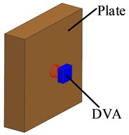
a) Power equipment attached with DVA
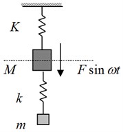
b) The theoretical
4. Position optimization design
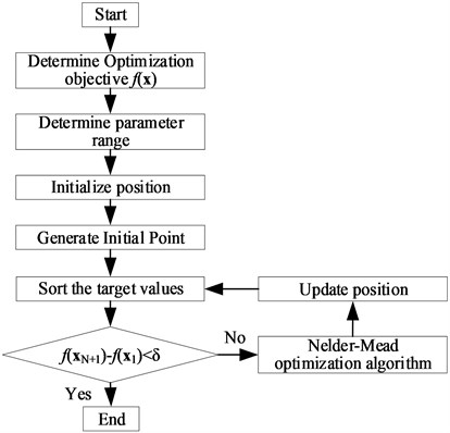
The objective of optimization design is to minimize the radiated sound power of the structure. The optimal parameter is the installation position of the DVA. The optimization algorithm is design based on Nelder Mead method.
In the actual analysis, the optimization objective shall be determined firstly. The analysis takes 200 Hz radiated sound power as the optimization target to achieve efficient control of sound radiation of 200 Hz equipment. Further, we need to determine the optimized location parameters and parameter variation range. Then, we should set the initial location and generate the initial point according to the initial location. The function values corresponding to the initial point are obtained and sorted from small to large. At the same time, the parameter variables need to be rearranged according to the new order. At this point, we need to judge whether the difference between the maximum value and the minimum value of the function is less than the given tolerance. If the difference value meets the conditions, it indicates that the parameter converges. The is determined as the optimal parameter variable. And the is the optimal target value. The location information needs to be updated using the Nelder Mead optimization principle when the difference between the maximum value and the minimum value of the function is greater than the tolerance requirement. We need to recalculate the function values, reorder the target values from small to large and start the next cycle. The optimization ends until the difference between the maximum value and the minimum value of the function meets the calculation tolerance requirements.
Fig. 3Optimization process of the position of DVA
5. Case study
In this section, the noise reduction performance of DVAs is firstly obtained by comparing the radiated sound power of the two systems before and after the installation the DVA. The optimal installation position is then obtained using the optimization algorithm. And the position optimization effect of the DVAs is discussed. The density of insulating oil is 993 kg/m3, the sound velocity of insulating oil is 1450 m/s, the density of steel is 7800 kg/m, and the Young’s modulus of steel is 2.16×10¹¹ Pa, steel Poisson’s ratio 0.28. Air density 1.2 kg/m3, air sound velocity 343 m/s. The maximum model grid is 0.1 m.
Fig. 4Acoustic radiation model of the transformer
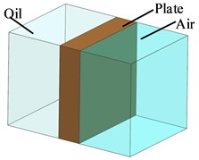
Fig. 5Acoustic radiation model of the transformer attached with the DVAs
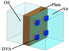
For ease of the analysis, the acoustic radiation model of the “oil-steel-gas” type transformer is established, simplifying the shell of the power equipment into unique plate structure, as shown in Fig. 4. The model could simulate the sound transmission characteristic of the power equipment composing insulating oil, equipment shell and external air. The unit sound pressure input is set on the insulating oil side of the model. The radiated sound power of the structure can be obtained by calculating the sound pressure at the air side of the model. Fig. 5 shows the sound radiation model of the transformer attached with DVA. In Fig. 5, four DVAs with natural frequency set as 200 Hz are evenly distributed on the equipment shell at the air side.
The objective function of optimization case is the radiated sound power at 200 Hz frequency. The optimization parameters are the positions of four DVAs. The constraint of the optimization case is set as that the position of the four DVAs are not placed at the same position. The optimization model parameters are listed in Table 1.
Table 1Optimization model parameters
Objective function | Radiated sound power at 200 Hz |
Optimization variables | Position of DVAs |
Initial value | (–0.200 m, 0.200 m), (0.200 m, 0.200 m), (0.200 m, –0.200 m), (–0.200 m, –0.200 m) |
Range of variables | (–0.400 m, 0.400 m), (–0.400 m, 0.400 m) |
Constraint condition | The distance between two DVAs are large than 0.060 m |
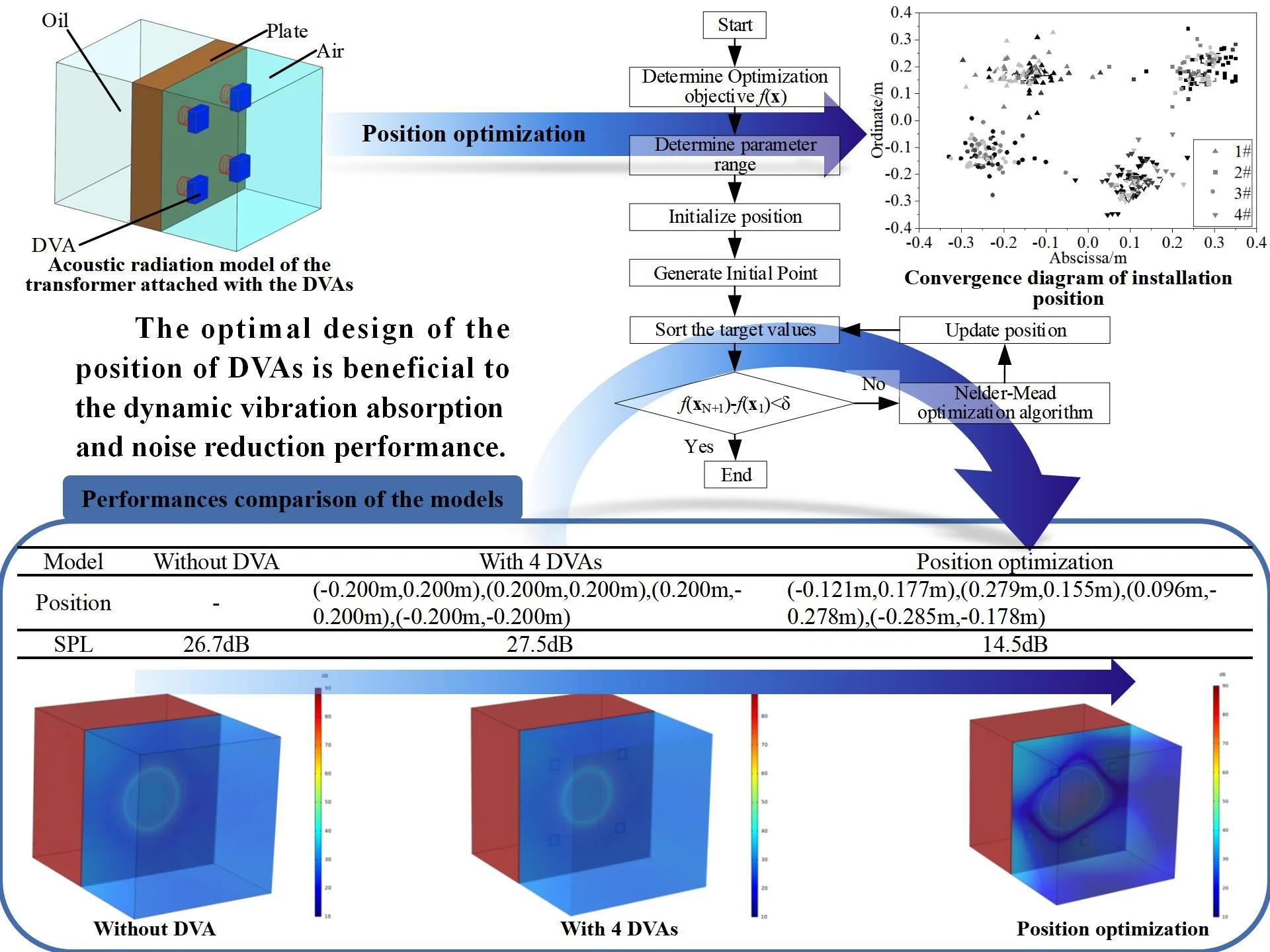
Fig. 6 shows the positions convergence diagram of the four DVAs. The color depth in the figure donates the level of the sound power, where the darker color represents the lower sound power level. The optimal positions of the four DVAs are (–0.121 m,0.177 m), (0.279 m, 0.155 m), (0.096 m, –0.278 m) and (–0.285 m, –0.178 m). The convergence curve of sound power level is shown in Fig. 7. In Fig. 7, the radiated sound power level generally decreases with iterations, with some fluctuation appear in the convergence curve.
In order to intuitively display the optimization effect of the position of the DVA, Fig. 8 gives the cloud diagram of the radiated sound field of the model before and after the position optimization.
Fig. 6Convergence diagram of installation position
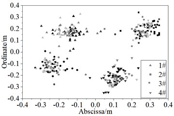
Fig. 7Sound power convergence diagram for position optimization
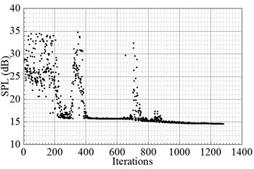
Fig. 8Cloud chart of the sound field of the models before and after installation of DVAs
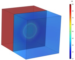
a) Before installation
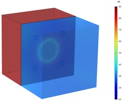
b) After installation
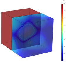
c) After location optimization
It is seen from the comparison between Fig. 8(a) and Fig. 8(c) that the sound pressure level of the radiated sound field is obviously controlled after the optimization of the position of the DVAs. The radiation sound pressure level decreases significantly. Comparing Fig. 8(a) and Fig. 8(b), it can be found that after the installation of the DVA with the same natural frequency as the target frequency, the radiated sound power of the system changes little compared with that before installation. This is mainly due to the installation coupling effect between the DVAs and the structure. The change of the actual stiffness of the DVAs causes the change of the action frequency of the DVAs. As a result, the expected effect is not achieved at the design frequency. It can be seen from the Fig. 8(a), Fig. 8(b) and Fig. 8(c) that the performance of the DVAs can be significantly improved by optimizing the position.
Fig. 9Radiated sound power curve of the model after position optimization
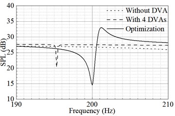
Fig. 9 shows the radiated sound power curve of the models without attached DVAs, with attached DVAs, and with attached optimized DVAs. In Fig. 9, the radiated sound power curve of the model without attached DVAs is a smooth straight line. The radiated sound power of the model without DVAs at 200 Hz is about 27 dB. The radiated sound power of the model with DVAs has no noise control effect at 200 Hz. However, it has noise reduction effect at 195 Hz. The radiated sound power of the model with optimized DVAs has obvious valley value at 200 Hz. The position optimized DVAs could realize efficient and accurate noise control at target frequency compared with non-optimized DVAs.
Table 2 shows the radiated sound power data of three models. The models include structure without DVAs, attached with four DVAs which natural frequency is 200 Hz and position optimized DVAs. The radiated sound power level of the unpowered DVAs is 26.7 dB. The radiated sound power level of the model with four DVAs respectively installed at the locations (–0.200 m, 0.200 m), (0.200 m, 0.200 m), (0.200 m, –0.200 m), (–0.200 m, –0.200 m) is 27.5 dB. The radiated sound power level of the model with the location optimized DVAs is 14.5dB. The optimized positions are (–0.121 m, 0.177 m), (0.279 m, 0.155 m), (0.096 m, –0.278 m), (–0.285 m, –0.178 m). The control performance using the location optimization optimized DVAs reaches a significant 12.2 dB reduction. The control performance using the DVAs without position optimization upwards 0.8 dB increase. The reason is that the actual frequency of the DVAs is offset due to the coupling effect of installation. The original design frequency is outside the action frequency range of the DVA. The above results verify the feasibility of the position optimization of the DVAs in the noise control of power equipment.
Table 2Performances comparison of the models
Model | Without DVA | With 4 DVAs | Position optimization |
Position | – | (–0.200 m, 0.200 m), (0.200 m, 0.200 m), (0.200 m, –0.200 m), (–0.200 m, –0.200 m) | (–0.121 m, 0.177 m), (0.279 m, 0.155 m), (0.096 m, –0.278 m), (–0.285 m, –0.178 m) |
SPL | 26.7 dB | 27.5 dB | 14.5 dB |
6. Conclusions
Considering the poor noise reduction performance of the power equipment after attaching with DVAs of which the natural frequency is consistent with the excitation frequency, the noise reduction technology of power equipment based on optimal position strategy is studied in this paper. The algorithm flow of location optimization of the DVA is proposed. The optimization design, analysis and verification were carried out on the object of transformer structure. The following conclusions are drawn from the analysis: (1) The DVA is very effective for noise control of power equipment which has low frequency line spectrum characteristics. (2) The actual operating frequency of the DVA will shift due to the installation coupling. The design frequency of the DVA will deviate from the actual frequency. Unreasonable design of DVA may be unfavorable to structural noise reduction. (3) The low frequency line spectrum noise control technology of power equipment based on optimal position strategy can compensate for the installation coupling effect to a certain extent. The optimal design of the position of DVAs is beneficial to the dynamic vibration absorption and noise reduction performance.
References
-
M. Tian and B. Gao, “Dynamics analysis of a novel in-wheel powertrain system combined with dynamic vibration absorber,” Mechanism and Machine Theory, Vol. 156, p. 104148, Feb. 2021, https://doi.org/10.1016/j.mechmachtheory.2020.104148
-
T. You, J. Zhou, D. J. Thompson, D. Gong, J. Chen, and Y. Sun, “Vibration reduction of a high-speed train floor using multiple dynamic vibration absorbers,” Vehicle System Dynamics, Vol. 60, No. 9, pp. 2919–2940, Sep. 2022, https://doi.org/10.1080/00423114.2021.1928248
-
J. S. Love, T. C. Haskett, and B. Morava, “Effectiveness of dynamic vibration absorbers implemented in tall buildings,” Engineering Structures, Vol. 176, pp. 776–784, Dec. 2018, https://doi.org/10.1016/j.engstruct.2018.09.050
-
H. Kwon and D. Cho, “Optimal design method of dynamic vibration absorber to reduce resonant vibration response of ship local structure,” Journal of the Society of Naval Architects of Korea, Vol. 59, No. 3, pp. 134–140, Jun. 2022, https://doi.org/10.3744/snak.2022.59.3.134
-
C. Yong, D. G. Zimcik, V. K. Wickramasinghe, and F. Nitzsche, “Research of an active tunable vibration absorber for helicopter vibration control,” Chinese Journal of Aeronautics, Vol. 16, No. 4, pp. 203–211, Nov. 2003, https://doi.org/10.1016/s1000-9361(11)60185-4
-
X. Wang, B. Yang, J. You, and Z. Gao, “Coarse-fine adaptive tuned vibration absorber with high frequency resolution,” Journal of Sound and Vibration, Vol. 383, pp. 46–63, Nov. 2016, https://doi.org/10.1016/j.jsv.2016.07.030
-
B. Mohammad Reza, “Mechanics of electrical transmission line robot inspector: pendulum as a dynamic vibration absorber,” E3S Web of Conferences, Vol. 162, p. 03004, 2020, https://doi.org/10.1051/e3sconf/202016203004
-
S. G. Hill and S. D. Snyder, “Design of an adaptive vibration absorber to reduce electrical transformer structural vibration,” Journal of Vibration and Acoustics, Vol. 124, No. 4, pp. 606–611, Oct. 2002, https://doi.org/10.1115/1.1500338
-
H. Cao et al., “Vibration and noise reduction of power transformer based on distributed tuned mass damper,” Smart Power, Vol. 49, No. 11, pp. 105–111, 2021, https://doi.org/10.3969/j.issn.1673-7598.2021.11.016
-
J. Ma, J. Wu, M. Geng, B. Ma, and C. Shen, “Optimal analysis on low frequency line spectrum sound control of power equipment using dynamic vibration absorber,” Vibroengineering Procedia, Vol. 41, pp. 117–123, Apr. 2022, https://doi.org/10.21595/vp.2022.22535
About this article

This work was financially supported by Science and Technology Project of State Grid Shaanxi Electric Power Company Limited (5226KY22000B).
The datasets generated during and/or analyzed during the current study are available from the corresponding author on reasonable request.
The authors declare that they have no conflict of interest.
