Abstract
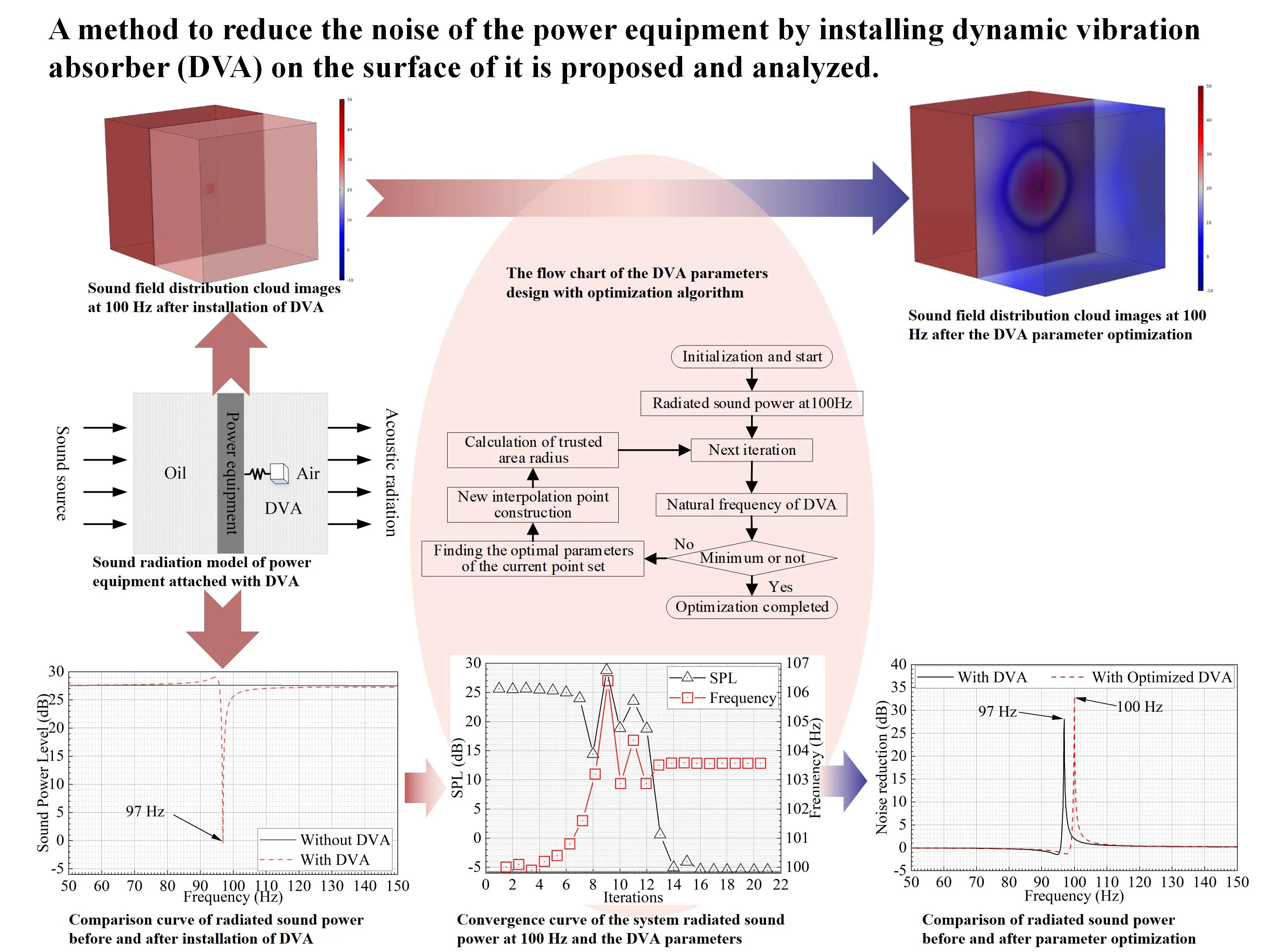
As generated by alternating current with the frequency of 50 Hz, the noise characteristics of power equipment reveal to be low frequency and line spectrum. The paper proposed a method to reduce the noise of the power equipment by installing dynamic vibration absorber (DVA) on the surface of it. The coupling between the attached DVA and the equipment may lead to undesirable frequency shift of the DVA itself, which will diminish the noise suppression effect of the whole system. The traditional passive DVA design method does not consider the effect of dynamic coupling. To solve this problem, global demodulation algorithm is applied to analyze the optimal parameters of DVA, which is integrated in the model of power equipment, to get the lowest single frequency radiated sound power level (SPL) of the equipment. The finite element model is established to verify the noise reduction optimal effect. The results show that the noise reduction effect of the optimized system is significantly improved compared with that using the classical parameter setting. The research can provide references for noise reduction optimization of power equipment in the future.
Highlights
- Low frequency noise of power equipment is effectively controlled with the application of DVA.
- The action frequency shift phenomenon of DVA due to the coupling affection between the DVA and the equipment is observed and demonstrated.
- A global demodulation optimization algorithm could modify the action frequency offset by the structure coupling. The low-frequency noise reduction performance of the power equipment with DVA could be improved using a global demodulation optimization algorithm.
1. Introduction
With the development of social economy and the continuous expansion of the city, more and more urban substations are gradually surrounded by residential areas. The noise characteristics of urban substations appear to be prominent low-frequency and linear spectrum. The long-standing noise emission of some substations have affected the normal life of surrounding residents. Given the low-frequency noise of substation, many scholars put forward noise control methods such as sound insulation, sound absorption and vibration isolation. These control methods effectively reduce the noise radiation of substation. X. Fan et. al [1] designed and installed the sound absorbing structure, acoustic insulation structure, and vibration isolator in distribution transformers. The measurement results show that the acoustic environment is distinctly improved after these treatments. J. Hu et. al [2] analyzed the effects of sound isolation of the barrier with different positions, heights and absorption materials in a 220 kV transformer. Traditional sound insulation, sound absorption and vibration isolation technologies can achieve significant noise reduction in high frequency, however, the effect of low-frequency noise control is quite limited.
DVA is an effective method to reduce low-frequency vibration and noise. It has a good suppression effect on low-frequency line spectrum noise and the feature is consistent with the 100 Hz, 200 Hz and other frequency line spectrum noise radiation characteristics of power equipment in power transmission and transformation projects. These frequencies are alternating current power frequency doubling in China. The DVA was invented by H. Frahm [3] in 1909, and it is applied to the anti sway water tank of German mail ship. In recent years, M. Jolly et. al. [4] have effectively reduced the radiated sound power near the vibration absorption frequency by attaching a DVA to the surface of the elastic plate. Considering the difficulty of low-frequency noise control of power equipment and the limits of traditional noise reduction technologies, the author proposed the low-frequency noise control technology for transformer based on DVA [5], [6]. The reduction of sound radiation can be achieved by installing the DVA on the equipment surface. The feasibility of the DVA method to reduce the sound radiation of power equipment has been verified in recent years.
Since the existing action frequency offset of the DVA after installed in the equipment, the integrated noise control effect may not be realized to its fullest. Z. Liu et. al [7] established dynamic equation of the DVA-rotor coupling system and designed optimization strategy to find the best design variable of the DVA by combining the coordinate solution of the response solution and the bounded boundary. A. Patel et. al [8] presented methods to tune an absorber integrated within a rotating milling tool holder accounting for its speed-dependent characteristic. Their results show that the optimally tuned absorber using the proposed approach behave better performance than classical methods of tuning the absorber. In order to realize the efficient control of low-frequency noise of power equipment, a sound radiation model of power equipment attached DVA is presented. The global demodulation algorithm with the objective function of the lowest radiated sound power at 100 Hz is applied and optimal design variables are figured out. The effectiveness of the proposed optimization algorithm is verified through a simplified model of power equipment with DVA. The research results implied that better noise reduction is achieved due to the optimization control method.
2. Noise reduction mechanism of plate with DVA
For homogeneous plate structure, the plate interacts with the attached impedance structure at the contact point. The effect of the local attached impedance structure feed back to the plate in the form of force or torque. As results, the plate dynamic equation [9] can be expressed as:
where, . is the density of plate material. is the the thickness of the plate. is the displacement of plate. is the bending stiffness of the plate. is the Young’s modulus of plate material. is the external excitation force at the coordinates (x, y) of the plate. is the force generated by the -th straight spring vibrator on the plate. Dirac function is a generalized function. The value of this function is equal to zero at all points except zero, and its integral in the whole definition field is equal to 1. This function refer to the unit impulse response function.
Considering at the coupling point, the force of the straight spring on the plate can be expressed as:
where, is the impedance of spring vibrator. is the displacement of the plate at position .
The impedance of the DVA is expressed as:
where, is the complex stiffness. is the damping loss factor of the damper.
After the DVA treatment, the vibration response of the plate can be calculated by substituting the impedance expression into the system vibration Eq. (1). Based on the data of structural vibration response, the radiated sound power of the system can be calculated by using Rayleigh integral method. The noise reduction performance of DVA can be obtained by comparing the changes of sound radiation of the system before and after DVA treatment.
3. Optimal noise reduction design
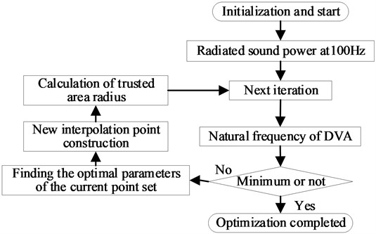
The line spectrum noise radiation of power equipment is serious, especially at the frequency doubling of 50 Hz such as 100 Hz and 200 Hz. The low frequency line spectrum noise radiation is difficult to control. The action frequency offset range of DVA is limited in the model of coupling structure with DVA. Considering that the optimal frequency is generally near the target frequency, a global demodulation algorithm [10] is selected to find out the optimal design parameters of DVA. In this optimal noise reduction design, the objective function is the minimum radiated sound power of the power equipment at 100 Hz and the optimization parameter is the natural frequency of the DVA. In this paper, the global demodulation optimization algorithm is used to optimize the DVA natural frequency. In the optimal flow, the optimization parameters range is initialized firstly. Then, the objective function is calculated with impose constraints. Finally, the frequency optimization is completed by iterating DVA natural frequency in the DVA/controlled-structure coupling system. A optimal algorithm flow based on global demodulation algorithm is shown in Fig. 2.
Fig. 1Structural diagram of DVA with single spring vibrator
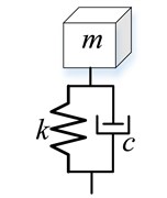
Fig. 2The flow chart of the DVA parameters design with optimization algorithm
4. Model analysis
4.1. Acoustic modeling of power equipment with DVA
A simplified fluid-solid-fluid acoustic model is established as shown in Fig 3. It simulate the sound transmission process of ‘internal insulating oil - equipment shell - external air’ in power equipment. Fig. 3(a) is sound radiation model of power equipment which simplified to homogeneous plate. Fig. 3(b) is sound radiation model of power equipment which simplified to homogeneous plate attached with DVA. The noise reduction effect can be obtained by comparing the changes of air side sound radiation before and after the installation of DVA. The weakest sound radiation at the target frequency can be achieved by changing the DVA parameters using the optimization algorithm. The optimal noise reduction is determined finally.
Fig. 3Sound radiation model of power equipment
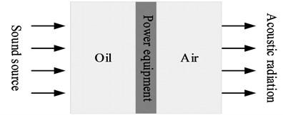
a) Homogeneous plate
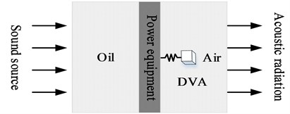
b) Homogeneous plate attached with DVA
4.2. Noise reduction performance
In China, the alternating current frequency is 50 Hz. The frequency of 100 Hz is an important line spectrum frequency characteristic in power equipment sound radiation. Therefore, 100 Hz is used as the noise reduction design target frequency. Before optimizing the design, we determine the parameters of the analysis model as follows. The density of insulating oil is 993 kg/m3. The sound velocity of insulating oil is 1450 m/s. The thickness of power equipment shell is 8 mm. The density of shell is 7800 kg/m3. The Young’s modulus of shell is 2.16×10¹¹ Pa. The Poisson’s ratio of shell is 0.28. The loss factor of shell is 0.001. The air density is 1.2 kg/m3. The air sound velocity is 343 m/s. The mass of DVA is 2 kg. The stiffness of DVA is 7.90 × 10⁵ N/m. The loss factor of DVA is 0.001.
Fig. 4Impedance curve of DVA
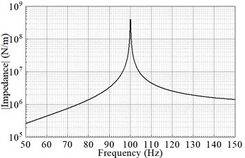
With the above parameters set, the impedance curve of the DVA can be obtained by using Eq. (3) and shown in Fig. 4. From Fig. 4, it can be clearly seen that the impedance of the DVA has peak at 100 Hz. According to the impedance theory, it can suppress the surface vibration of power equipment when the additional impedance is large. Thus, the control of surface acoustic radiation of power equipment can be realized.
Fig. 5Comparison of sound field distribution cloud images at 100 Hz
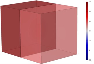
a) Before installation of DVA
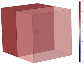
b) After installation of DVA
The sound radiation of the systems between before and after the installation of DVA with natural frequency of 100 Hz are analyzed. The comparison of the cloud images of the radiated sound field of the two different models are given as Fig. 5. It can be seen from the Fig. 5 that the sound pressure on the oil side basically are same and the sound pressure of the air side is small after DVA installation situation. The radiated sound power of the model at 100 Hz are 27.59 dB and 25.59 dB before and after the DVA installation respectively. The DVA installation reduces the value of the sound pressure on the air side. Therefore, the DVA treatments realizes the sound radiation control for power equipment. The sound power reduction is 2 dB which is not obvious with this parameter setting of DVA.
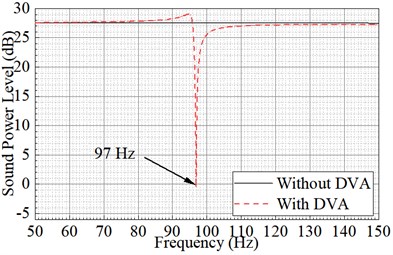
Fig. 6 is comparison curve of radiated sound power before and after installation of DVA from 50 Hz to150 Hz. In Fig. 6, the sound radiation of the model is basically stable around 28 dB before the DVA installation. The sound radiation curve of the model show obvious valley near 97 Hz after the DVA with natural frequency of 100 Hz installed on the model. The radiated noise of the model is significantly controlled at 97 Hz. The radiated sound power at 100 Hz has decreased, but the control effect is far less than that at 97 Hz. This is different from the expectation of the most noise reduction at 100 Hz. This frequency offset is due to the coupling between the power equipment and the DVA. The maximize control effect of sound radiation at 100 Hz could be realized by adjusting the DVA stiffness parameters or natural frequency. The research on the optimization design of low-frequency noise control of power equipment by using a global demodulation optimization algorithm is carried out in next section.
Fig. 6Comparison curve of radiated sound power before and after installation of DVA
4.3. Parameters optimization
The basic parameters of the noise reduction global demodulation optimization model for power equipment attached with DVA are listed in Table 1. The global demodulation optimization model of noise reduction is established and the optimization calculation is carried out to obtain the DVA natural frequency parameters.
Table 1Parameters of global demodulation optimization model
Optimization parameters | DVA natural frequency |
Parameter initial value | 100 Hz |
Parameter range | 50 Hz-150 Hz |
Tolerance | 0.001 dB |
Objective function | SPL at 100 Hz |
Scaling factor | 0.5 |
Constraint condition | Null |
Fig. 7 shows the convergence curve of radiated sound power at 100 Hz, DVA natural frequency and DVA stiffness with the number of iterations. From Fig. 7(a), it can be clearly seen that the radiated sound power of the system at 100 Hz converges and stabilizes at –5.51 dB after 21 iterations. The DVA natural frequency finally converges to 103.56 Hz. From Fig. 7(b), the optimal spring stiffness is 8.47×10⁵ N/m when the curves converge.
Fig. 7Convergence curve of the system radiated sound power at 100 Hz and the DVA parameters
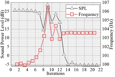
a) DVA natural frequency
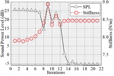
b) DVA stiffness
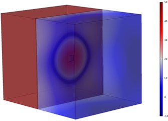
The noise reduction effect corresponding to the optimization parameters can be obtained by inputting the parameters into the sound radiation model of power equipment attaching DVA. The cloud images of sound field distribution at 100 Hz before and after DVA parameter optimization are given in Fig. 8. It can be seen from Fig. 8 that the sound pressure on the right air side after optimization at 100 Hz is greatly decreased compared with that before optimization in Fig. 5(b).
Fig. 8Comparison of the sound field distribution cloud images of the power equipment models at 100 Hz before and after the DVA parameter optimization
The radiated sound power curve after optimization from 50 Hz to 100 Hz is given in Fig. 9. It can be seen from Fig. 9 that the radiated sound power of the system has an obvious valley value at 100 Hz after the optimized design. The radiated sound power reduction of the system at 100 Hz is 33.1 dB, which is 2 dB before optimization in Fig. 6. The frequency offset problem is solved based on a global demodulation control optimization algorithm.
Fig. 9Sound radiation curve after global demodulation control optimization
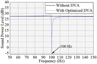
Fig. 10Comparison of radiated sound power before and after parameter optimization
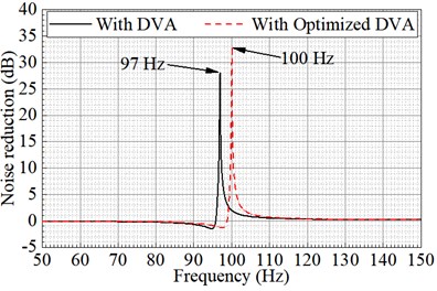
The sound reduction of system before and after DVA parameter optimization are given in Fig. 10. In Fig. 10, the most noise reduction performance appears at 100 Hz after optimization. However, the best noise reduction performance appears at 97 Hz before optimization. The DVA action frequency deviates from the preset frequency after it attached in the power equipment. Therefore, the DVA with the preset parameter could not achieve the most sound reduction effect at objective frequency. While the best sound control performance could be realized through the proposed optimal process in this paper.
5. Conclusions
In order to realize the low frequency line spectrum noise control of substation, the paper proposed an optimal analysis of the model of the power equipment attaching DVA treatment. The optimal frequency offset phenomenon of the DVA attached to structure is observed in this paper. A global demodulation optimization algorithm is designed for achieving the minimum radiation sound power at objective frequency. The main conclusions are following: (1) Low frequency noise of power equipment with DVA is effectively decreased. (2) The action frequency shift phenomenon of DVA due to the coupling affection between the DVA and the equipment is observed and demonstrated. (3) A global demodulation optimization algorithm could modify the action frequency offset by the structure coupling. The low-frequency noise reduction performance of the power equipment with DVA could be greatly improved using a global demodulation optimization algorithm.
References
-
X. Fan et al., “Environmental noise pollution control of substation by passive vibration and acoustic reduction strategies,” Applied Acoustics, Vol. 165, p. 107305, Aug. 2020, https://doi.org/10.1016/j.apacoust.2020.107305
-
J. Hu et al., “Substation noise reduction effect of barrier and analysis of influencing factors,” Engineering Journal of Wuhan University, Vol. 50, No. 1, pp. 75–80, 2017.
-
Hermann Frahm and Hermann Frahm, “Device for damping vibrations of bodies.,” U.S. Patent 10487903, 1909.
-
M. R. Jolly and J. Q. Sin, “Passive tuned vibration absorbers for sound radiation reduction from vibrating panels,” Journal of Sound and Vibration, Vol. 191, No. 4, pp. 577–583, Apr. 1996, https://doi.org/10.1006/jsvi.1996.0141
-
J. Wu et al., “Research on transformer noise reduction method using dynamic vibration absorption,” Technical Acoustics, Vol. 40, No. 6, pp. 851–857, 2021.
-
L. Wang et al., “Urban 110 kV indoor substation noise analysis and control schemes: A real case study,” Applied Acoustics, Vol. 183, p. 108290, Dec. 2021, https://doi.org/10.1016/j.apacoust.2021.108290
-
Z. Liu, Q. Xu, W. Li, H. Yao, and B. Wen, “Parameter optimization method of rotor dynamic vibration absorber,” Hangkong Dongli Xuebao/Journal of Aerospace Power, Vol. 33, No. 10, pp. 2359–2366, Oct. 2018, https://doi.org/10.13224/j.cnki.jasp.2018.10.007
-
A. Patel, D. K. Talaviya, M. Law, and P. Wahi, “Optimally tuning an absorber for a chatter-resistant rotating slender milling tool holder,” Journal of Sound and Vibration, Vol. 520, p. 116594, Mar. 2022, https://doi.org/10.1016/j.jsv.2021.116594
-
F. Fahy and P. Gardonio, 2nd ed. New York: Academic Press, 2007.
-
M. J. D. Powell, “The BOBYQA algorithm for bound constrained optimization without derivatives,” University of Cambridge, Cambridge, Jan. 2009.
About this article

This work was financially supported by Science and Technology Project of State Grid Shaanxi Electric Power Company (5226KY22000B).
