Abstract
In order to blind estimate pseudo-code (PN) code phase modulation and linear frequency modulation composited fuzecarrier frequency. By improving the traditional Duffing oscillator detection model of strong reference signal, an approximate carrier frequency blind estimation method by small-scale periodic Duffing oscillator is proposed in this paper. In this method, the internal dynamic frequency is used to approximate the changes of the output time domain and phase diagram of the chaotic system during the frequency to be measured. Then calculate the different frequency to blind estimate the carrier frequency of the signal. This method widens the range of frequency detection and can realize blind frequency estimation with less prior knowledge. The parameter estimation effect of the approximate carrier frequency estimation method based on small cycle Duffing oscillator under different signal to noise ration (SNR) is simulated and analyzed in this paper. The results show that this method has better parameter estimation performance than the traditional composited fuze frequency estimation method, especially in the environment of low SNR.
1. Introduction
The combination of PN code phase modulation and linear frequency modulation fuze combines the advantages of PN code phase modulation fuze and linear frequency modulation fuze. It not only has good range accuracy, but also has strong anti-jamming performance. It has been widely used in recent years [1-2]. For the interference of this kind of fuze signal, the interference efficiency of preset periodic modulation interference waveform is low. While digital radio frequency memory (DRFM) repeater interference has high hardware requirements for interference equipment, and the effect of interfering with this modulation signal is poor [3]. Therefore, reconstituted jamming is often used in the jamming method of this fuze, and the key to reconstituted jamming lies in its parameter estimation.
To solve this problem, references [4, 5] first used the square method to eliminate the influence of pseudo-random sequence, and obtained the linear frequency modulation signal. Then estimated the pseudo-random sequence. But this method requires that the pseudo-random code width be known, and the parameter estimation effect is poor when the SNR is less than 2 dB. Reference [6] proposed some estimators based on cyclic spectral density function. Although this method does not need to know the pseudo code sequence, it needs to know the symbol time width and carrier frequency. The method of strong reference signal detection system based on Duffing oscillator proposed in reference [7] can estimate the parameters of composited fuze better. But it needs priori knowledge of narrow frequency bandwidth. It can be seen that most of the current methods of parameter estimation of PN code phase modulation and linear frequency modulation composited fuze need priori conditions, especially the carrier frequency under low SNR. Therefore, how to estimate the carrier frequency under low SNR better is important for the interference of this fuze.
Because of the Duffing oscillator’s immunity to noise and sensitivity to specific frequency periodic signals, it has broad application prospects in the field of weak signal detection. A method that requires low signal frequency and wide bandwidth to capture and estimate the signal is needed to realize the blind estimation of the signal frequency of the composited fuze. Therefore, this paper proposed a frequency estimation method based on small-scale periodic Duffing oscillator approximation, which can realize the blind frequency estimation of composited modulation fuze signal with less prior knowledge.
2. Analysis of Duffing oscillator signal detection model
2.1. Small scale periodic state detection model
This paper presented a new chaos detection method, which can blind estimate the carrier frequency of composited fuze signal and has high estimation accuracy. In this method, the amplitude of the internal dynamic reference signal of the system is set to 0.04, so that the system is in a small-scale periodic state [8]. The Duffing oscillator expression used in this paper is:
where, is the signal to be measured, is random disturbance and noise. is internal power reference frequency, is Internal dynamic reference amplitude, is internal dynamic initial phase. The actual Duffing oscillator can be changed by to adapt to signals of different frequencies. If the system above ignores the noise, the total internal policy dynamic signal can be expressed as:
where:
represents the equivalent internal policy dynamic signal amplitude of Duffing oscillator system, and represents the frequency difference between the signal to be measured and the reference internal policy dynamic signal. is the phase difference between the signal to be measured and the internal power signal. is the equivalent dynamic phase.
The value of should be in the range of []. Therefore, if the value of Duffing oscillator 0.04, when the value of is less than 0.36, the small-scale periodic state can be maintained.
2.2. Comparison between strong reference signal detection system and small-scale periodic detection model
Reference [9] proposed a broadband weak signal detection method based on Duffing oscillator array. This method used the sensitivity of Duffing oscillator strong reference signal from chaotic state to large-scale periodic state, and can detect broadband weak signal.
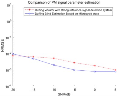
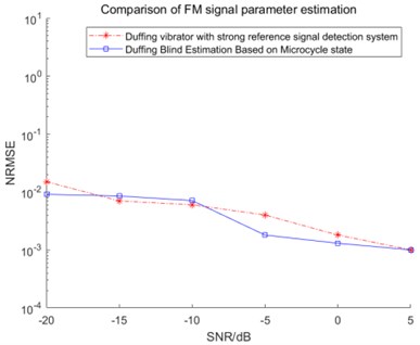
For comparison, Fig. 1 shows the normalized root mean square error (NRMSE) comparison results of two methods for frequency modulation (FM) signal and pseudo-code phase modulation (PM) signal respectively. It can be seen from the figures that the two methods are basically equivalent in the estimation performance of FM signal parameters. However, the small cycle state model has obvious advantages in estimating the PM signal. Meanwhile, strong reference signal has the following problems in carrier frequency estimation:
(1) Due to the limited frequency identification range of a single oscillator, it is impossible to capture the signal when the frequency difference is large. In order to realize frequency estimation, more oscillators need to be set.
(2) When estimating carrier frequency of strong reference signal system, priori knowledge of frequency is required. Because only the difference between the internal dynamic frequency and the frequency to be estimated meets in each array can cause the change of chaotic state. Therefore, when the frequency bandwidth is large, the number of oscillators will increase.
(3) In this method, the internal dynamic amplitude is set to be approximately equal to the threshold. When the total internal policy dynamic signal and are approximately equal, the immunity of chaotic system to noise will decrease [10]. In addition, when the internal power frequency changes, the threshold will also fluctuate slightly. If is close to , intermittent chaos may not be generated under the action of the signal to be measured [11], especially for PM and liner FM composited signals. Changes in phase and frequency will cause greater changes in and . Thus, it is more difficult to distinguish intermittent chaotic states.
Therefore, we need improve the interception ability when the frequency difference is large, so as to realize the fast interception ability of the signal. And avoid the change of phase diagram output state as much as possible to improve the estimation accuracy.
Fig. 1Comparison of two methods under FM fuze and PN code phase modulation fuze signal
3. Approximate frequency estimation method by small-scale periodic Duffing oscillator
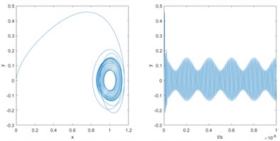
Based on the frequency detection model above, an oscillator with fixed reference frequency and internal dynamic reference signal amplitude is established in this paper. When the oscillator frequency gradually approaches the signal to be measured, the sequence diagram changes from disorder to order and shows periodic changes. The envelope part shows a similar periodic change. And the period gradually increases with the approach of frequency. On the contrary, when the frequency of the oscillator is gradually away from the frequency of the signal to be measured, the change of the sequence diagram shows the opposite change. At the same time, it can be found that the periodic law of - envelope is more obvious. Therefore, this paper used - time series analysis method to estimate the difference frequency.
Fig. 2 shows the phase trajectory and - sequence diagram when = 100 MHz and the internal dynamic frequency of Duffing oscillator gradually approaches the frequency of the signal to be measured. Based on the law above, the data analysis model is established to analyze the output phase diagram state and - sequence diagram. By analyzing the envelope periodic change in the - sequence diagram, the difference between the signal to be measured and the internal dynamic frequency of Duffing oscillator can be obtained. After measurement, analysis and calculation, the envelope part of the output sequence diagram is transformed by FFT. It contains the frequency difference information between the internal dynamic frequency of Duffing oscillator and the signal to be measured.
In the figure above, the known frequency signal can be estimated. When the frequency of the signal is unknown, there is only a certain frequency band information or no prior knowledge. In order to make the model and use method more applicable to various scenes and environments, the method of blind frequency estimation of the model is as follows:
First, if we can roughly estimate the frequency range by using the methods such as intercepting the spectrum of the signal to be measured. We can set the internal policy signal power frequency of Duffing oscillator to take an appropriate value. And make the frequency between . If there is no prior knowledge, set and adjust the internal dynamic frequency of the Duffing oscillator array, the frequency approach law above can be used to approach the frequency of the signal to be measured. Until the difference between the dynamic frequency of the internal policy signal and the frequency of the signal to be measured is less than 0.5.
Then set the Duffing oscillator array containing 3 Duffing oscillators, the dynamic frequency of the internal policy signal set in step 1 is used as the frequency of oscillator 1. The frequencies of oscillator 2 and oscillator 3 are set to 1.1 and 1.2 respectively. Then according to the frequency variation, obtained the FFT transformation of the y-t envelope of the sequence diagram of the three oscillators. According to the transformation law above of difference frequency, it is obtained whether the internal policy dynamic frequency is on the left or right of the frequency to be measured.
Finally, since the frequency variation range is between the start and end frequencies, the difference frequency also changes in a certain range. Therefore, five extremely high values after FFT can be taken as the difference frequency estimation value as . If the frequency to be measured is on the left side, the estimated values On the other side, the estimated value is The average of the estimated values of the three oscillators is the final value.
Fig. 2Frequency gradually approaches to the signal frequency to be measured, phase trajectory diagram and y-t sequence diagram
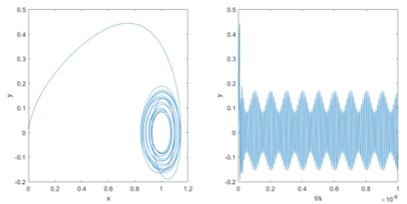
a) 85 MHz
b) 90 MHz
c) 95 MHz
4. Verification of frequency parameter estimation method of composited modulation fuze
In this paper, the amplitude of PN code phase modulation and linear frequency modulation signal is set to 0.1. The initial frequency 2×100×106 rad/s. The termination frequency 2×103×106 rad/s. Modulation period is 4×10⁻⁶ s. The symbol width of pseudo-random sequence is 300 ns. The pseudo-random sequence within 6×10⁻⁶ s is 10000111110101001100. In order to blind estimate the carrier frequency of composited fuze signal. Gaussian noise is added while adjusting the value of internal dynamic signal frequency of Duffing oscillator. Adjust the variance of Gaussian noise to change the SNR of the signal to be measured. Observe the simulation results under different SNR.
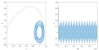
After the three oscillators are calculated according to the above method, the three estimated frequencies with the smallest difference are averaged to obtain the final frequency estimation result. Fig. 3 shows the simulation results of frequency with 2×80×106 rad/s.
Fig. 3Simulation results of three oscillators when taking the frequency is 80 MHz
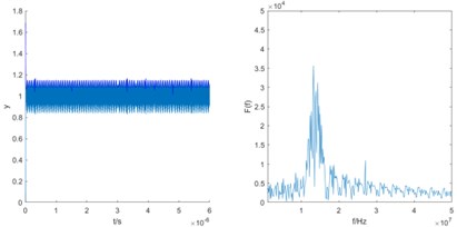
a) 80 MHz
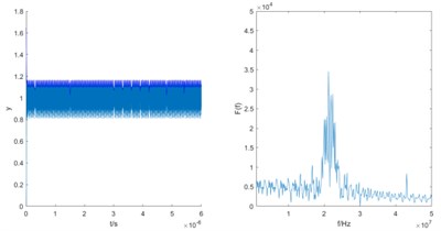
b) 88 MHz
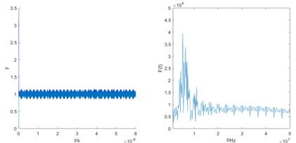
c) 96 MHz
It can be analyzed that the difference frequency is gradually close and the step is 8 MHz. Therefore, it can be determined that the frequency of the signal to be estimated should meet . According to the calculation principle of the first case, the estimated frequency is 2×101.5×106 rad/s.
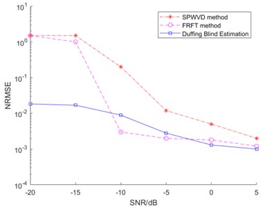
In order to verify the generality, several experiments are carried out under several SNR. For comparison, smooth pseudo Wigner-Ville distribution (SPWVD) method and fractional fourier transform (FRFT) method are simulated under different SNR. The conditions of these two methods are the same as those of Duffing oscillator method. However, when the SNR is less than −20 dB, the performance of this two methods is poor. Therefore, this paper only compared the three methods when the SNR is −20 dB to 5 dB. The results of carrier frequency normalized root mean square error (NRMSE) of the three methods are shown in Fig. 4.
As shown in Fig. 4, compared with SPWVD and FRFT methods, the Duffing oscillator method proposed in this paper works under different SNR better, especially in the case of low SNR. The carrier frequency of composited fuze can be estimated more accurately. Meanwhile, the blind estimation method based on Duffing oscillator has little difference and is more stable at −20 dB to 5 dB. Moreover, Duffing oscillator blind estimation method can be realized and requires less priori knowledge. At −20 dB SNR, the NRMSE based on SPWVD and FRFT methods is more than 1.5, while the NRMSE of the blind estimation method based on Duffing oscillator is only about 0.01.
Fig. 4Comparison of blind estimation results based on SPWVD, FRFT and Duffing oscillator
5. Conclusion
Based on the regular change of the small-scale periodic state of Duffing oscillator when the internal dynamic frequency is close to the frequency of the signal to be measured, this paper proposed an approximate blind frequency estimation method based on small periodic Duffing oscillator to estimate the carrier frequency of PM and linear FM composited fuze. Compared with the traditional Duffing oscillator strong reference internal policy dynamic amplitude system, this method widens the frequency detection range and realizes the detection of carrier frequency of composite modulation signal under the condition of low signal-to-noise ratio and less prior knowledge. The simulation results show that for the composited modulation fuze signal, the model can still accurately detect the carrier frequency of the composited signal in the environment of low SNR. Compared with the traditional estimation methods, the effect is better and it requires less priori knowledge.
References
-
H. C. Zhao, Radio Fuze Design Principles and Methods. Beijing: National Defense Industry Press, 2012, pp. 94–114.
-
S. Nandi and D. Kundu, “Estimation of parameters in random amplitude chirp signal,” Signal Processing, Vol. 168, p. 107328, Mar. 2020, https://doi.org/10.1016/j.sigpro.2019.107328
-
K. Wang, X. Yan, Q. Yang, X. Hao, and J. Wang, “Weak signal detection based on strongly coupled duffing-van der pol oscillator and long short-term memory,” Journal of the Physical Society of Japan, Vol. 89, No. 1, p. 014003, Jan. 2020, https://doi.org/10.7566/jpsj.89.014003
-
P. Wang, J. Zhu, and B. Tang, “Theoretical performance analysis for parameter estimation of hybrid modulated signal combining pseudo-random binary-phase code and linear frequency modulation,” Journal of Electronics and Information Technology, Vol. 38, No. 2, pp. 472–477, 2016, https://doi.org/10.11999/jeit150523
-
D. He, T. Zhang, L. Gao, and H. Gao, “Blind estimation for PN code of LFM-PRBC signal based on DPT and spectrum shifting,” in 2012 5th International Congress on Image and Signal Processing (CISP), pp. 1430–1434, Oct. 2012, https://doi.org/10.1109/cisp.2012.6469698
-
J. Liu and J. Tian, “The ambiguity function analysis of pseudo-random binary phase code combined with linear frequency modulation signal,” Journal of Jinling Institute of Technology, Vol. 31, No. 1, pp. 1–7, 2015, https://doi.org/10.16515/j.cnki.32-1722/n.2015.01.015
-
K. Wang, “Fuze signal parameter estimation method based on Duffing oscillator,” Beijing Institute of Technology, 2019.
-
H. Shi and W. Li, “Research on weak resonance signal detection method based on duffing oscillator,” Procedia Computer Science, Vol. 107, pp. 460–465, 2017, https://doi.org/10.1016/j.procs.2017.03.090
-
S. K. Liu, X. P. Yan, P. Li, and H. H. Yu, “Design of Jamming signal on pseudo-random code phase-modulation and pulse doppler combined fuze based on code reconstruction,” Acta Armamentarii, Vol. 39, No. 6, pp. 1088–1094, 2018.
-
M. Shi and J. C. Liu, “Applying improved chaos system to weak signal detection,” in International Industrial Informatics and Computer Engineering Conference, pp. 1591–1595, 2015.
-
A. H. Costa, R. Enríquez-Caldera, M. Tello-Bello, and C. R. Bermúdez-Gómez, “High resolution time-frequency representation for chirp signals using an adaptive system based on Duffing oscillators,” Digital Signal Processing, Vol. 55, pp. 32–43, Aug. 2016, https://doi.org/10.1016/j.dsp.2016.04.008
About this article

This research has been funded in 61973037 by the National Natural Science Foundation of China.
