Abstract
A design scheme of Duffing Chaotic circuit module is proposed based on Multisimin study. The operational amplifier is used to construct integrating circuit. The Duffing chaotic circuit is also designed based on the integrating circuit. The results can be shown in a virtual oscilloscope by phase trajectory. The bifurcation results of Duffing oscillator solved by the circuit module are consistent with that obtained by Matlab. The Duffing equation in critical state is selected as Chaos Inspection System (CIS), which is used to identify weak signal with strong noise. Simulation examples show that the chaotic circuit designed in this study can successfully identify many kinds of weak signals, such as sine wave, triangle wave, and square wave etc. This work provides a theoretical basis for the hardware of CIS of weak signal with strong noise.
1. Introduction
Non-destructive Testing (NDT) technology can timely detect structural defects in the early stage of structural service, which is an important means to ensure the safe service of engineering components. However, in the early stage of structural damage, the obtained damage characteristic signals are often very weak due to the small defect, which is very likely to be submerged in the noise and cause missed detection. It is particularly important to improve the detection sensitivity of small defects. Due to the traditional domain detection method of weak signal time, the threshold of the input SNR is limited to a certain extent [1]. A new theory is needed and further improve the detection efficiency of weak signals with lower SNR.
Based on the parameter sensitivity of the Duffing chaotic system and the noise immunity, the chaotic weak signal detection theory developed has been favored by many researchers [2-4]. The basic principle is that the Duffing system in a critical state of chaos will undergo significant state changes under external disturbances. In actual operation, the driving force frequency of Duffing system is set according to the frequency of the signal-to-be-tested, and the damping is a constant. Adjusting the amplitude of driving force, the system in a critical state of chaotic phase transition is selected as a Chaos Inspection System (CIS). Adding a signal-to-be-test to the driving force item, the CIS will happen the chaotic phase transition if the signal contains a weak signal of the same frequency, otherwise, it will remain unchanged [5-8]. At present, the weak signal inspection technology based on CIS have been applied in many fields. For example, Akilli et al. [9] successfully detected Electroencephalogram (EEG) signals with CIS. Li et al. [10] proposed a differential double coupling Duffing oscillator method to detect the measured underwater weak target signal. Li et al. [11] proposed a CIS method, which was successfully used to detect the signal leaked by the real HDMI cable in the shielding room during transmission. Srinivasan et al. [12] studied the detection ability of various signals of Duffing chaotic system, and successfully identify the triangle wave, and saw tooth wave. Zhang et al. [13] and Wu et al. [14] considered the weak ultrasonic guided wave signal generated by tiny defects in the pipeline, and successfully detected the modulated pulse signal using the Duffing chaotic system, which provided an excellent cases for the Duffing chaotic system for NDT.
However, the above words are mainly depending on software programming. The solution speed is slow, and it needs to rely on a third-party development platform. In this study, a Duffing chaotic circuit scheme will be designed by Multisim, which is a theoretical base for the hardware of CIS of weak signal with strong noise. Obviously, a CIS based on hardware need not D/A conversion and directly analyze the analog signal, which can improve the efficiency. The remaining parts is outlined as follows: the principles of the CIS for detecting weak signal is presented in Section 2. The design scheme of Duffing chaotic circuit is introduced in Section 3, and some experiments are carried out. Finally, some conclusions can be drawn in Section 4.
2. The inspection principle of a weak signal by Duffing system
Duffing system is a kind of nonlinear system, which has rich nonlinear characteristics, such as periodicity, chaos, bifurcation, period-doubling, and other characteristics. The typical Duffing oscillator is shown in Eq. (1):
in which, represents the displacement, is the nonlinear restoring force, is the damping ratio, and is the periodic driving force. Let , is thesignal-to-be-detection, transform the time variable into , then the above formula becomes:
To solve Eq. (2), it can be written after reduced-order as:
In this study, a 70 kHz weak signal will be inspected. Therefore, 0.44 rad/μs. Without loss of generality, 0.4. Changing the amplitude of driving force in the range of , the displacement bifurcation diagram versus the amplitude is shown in Fig. 1. Here, the initial value , the integral step is 0.02 μs as, the total time is 500 external excitation cycles. It can be seen that when the amplitude gradually increases from 0 to 1, the system experiences small-scale period, chaos and large-scale period state, etc. A critical 0.6747 is selected as a critical point of chaotic phase transition. The Duffing system in the critical state will be used to identify weak signals.
3. Design scheme of Duffing chaotic circuit
3.1. Duffing chaotic circuit
Integral operation is a core. A typical integrated circuit is shown in Fig. 2. When is input into the operational amplifier, the output is the integral of the . They are satisfied as:
Fig. 1Displacement bifurcation diagram of the system versus the driving force amplitude
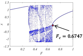
Fig. 2Integral amplifier circuit
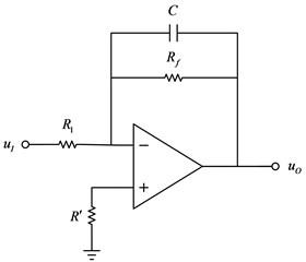
In which, is a capacitor, which introduces the AC parallel voltage negative feedback to make the operational amplifier work in the linear region. In the actual circuit, a large feedback resistor needs to be connected in parallel at both ends of the capacitor to suppress the integral drift phenomenon that occurs due to various reasons, and the balance resistor is connected to the non-inverting end to adjust the matching of the input and feedback resistor, thereby suppressing the bias current. is the input resistance. In this study, an inverting integrator composed of an operational amplifier and a resistor and a capacitor will be used to the integral operation and integral operational amplifier in the Duffing oscillator [15, 16].
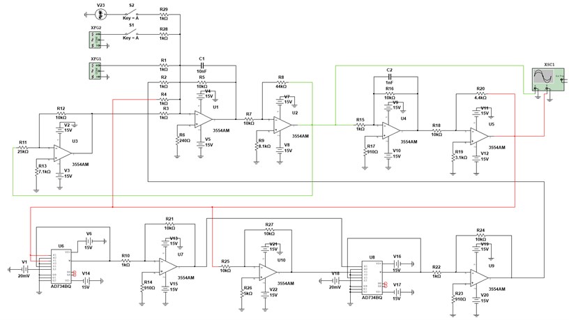
The Duffing chaotic circuit is designed according to Eq. (3) as shown in Fig. 3. Among them, the operational amplifier is 3554 AM, the multiplier is AD734BQ, and some capacitors and resistors are used to build the circuit. The power supply voltage of the operational amplifier and the multiplier is ±15 V. According to the parameters of a critical state for Duffing chaotical system, each component is configured as: 1 kΩ, 44 kΩ, 4.4 kΩ, 10 nF, 1 nF, 10 kΩ.
Fig. 3Overall design circuit diagram
According to Kirchhoff's law of current, it can be known that the circuit shown in Fig. 3 is equivalent to solving the following equations:
Substitute each parameter into Eq. (5) and the following can be obtained:
It can be seen from Eq. (6) that the circuit accurately simulate the solution of the Eq. (3). Among them, the signal source connected to represents the periodic driving force term in the Duffing oscillator. The output of operational amplifier represents in Eq. (3), and the output of operational amplifier represents in Eq. (3). The phase trajectory is plotted by the time history of and in the oscilloscope XSC1.
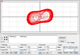
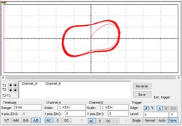
In Multisim, the virtual signal generatorXFG1 simulates the driving force item of Duffing equation, and the virtual signal generator XFG2 generates a signal-to-be-detection. If switch S1 is open and the signal in XFG2 is not input to the circuit, the circuit is equivalent to the Eq. (1). If switch S1 is closed and the signal in XFG2 is not fed into the circuit, the circuit is equivalent to the Eq. (2) or Eq. (3), which is a CIS. Here, it should be noted that the relationship between the Root Mean Square (RMS) voltage generated by the signal source and the input value is: . For example, the signal source amplitude of 0.4666 is equivalent to a driving force amplitude of 0.659987. The phase trajectory is plotted as shown in Fig. 4(a) when 0.4666, which shows that the system is chaotic. If the signal source amplitude is increased a little, it becomes 0.4667, that is, 0.660013, the system will suddenly change to a periodic state as shown in Fig. 4(b). This result is basically consistent with that in Fig. 1. Therefore, 0.4666, that is, 0.6599, is selected as the critical value of the system. Fig. 4(a) is the original phase trajectory of detection system. A weak signal could be identified from observing the changes of phase trajectory after inputting the signal-to-be-detected. If a sudden change occurs, it can be determined that the signal-to-be-detected contains a periodic signal with the same frequency as the driving force of the Duffing system.
Fig. 4System phase trajectory under the same amplitude
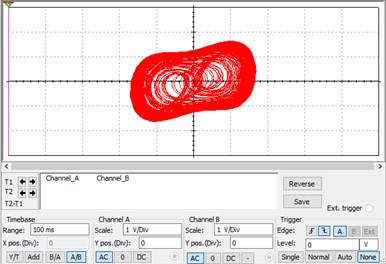
a) System phase trajectory when 0.4666
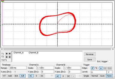
b) System phase trajectory when 0.4667
4. Weak signal detection under strong noise
4.1. Noise immunity analysis
To illustrate the ability of the chaotic circuit to detect weak signals under strong noise, the following noise model is constructed:
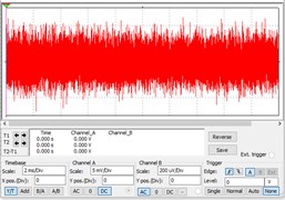
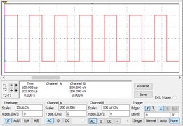
where, is a pure periodic signal, is a Gaussian white noise with distribution of (0, 1), is noise level, an SNR of 100, a resistance of 100 kΩ, and a bandwidth of 70 kHz. There are sinusoidal signals with an amplitude of 0.0002, pure noise signals and sinusoidal signals submerged by the noise. The time-domain diagrams are shown in Fig. 5(a)-(c). It can be seen that the sinusoidal signal mixed with noise has completely submerged in the noise.
Fig. 5Time-domain diagram of the system under different disturbances
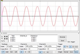
a) Sine wave
b) Noise
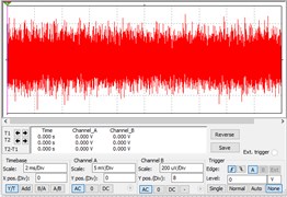
c) A sinusoidal signal obscured by noise
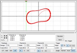
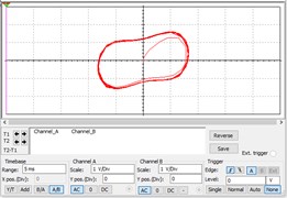
After adding the above three signals to the Duffing chaotic circuit, the results are shown in Fig. 6(a)-(c). It can be seen that when a weak sinusoidal signal is an input into the circuit, the system changes from a chaotic state to a large-scale periodic state, as shown in Fig. 6(a); however, after adding pure noise, the phase trajectory of the system is shown in Fig. 6(b), which has almost no effect and is still in a chaotic state. Adding a sinusoidal signal containing noise into the circuit, the state of the system becomes a large-scale periodic state as shown in Fig. 6(c). These results verify that the circuit has a strong ability to detect weak sinusoidal signals in a strong noise background.
Fig. 6The results of Phase trajectories considering noise influence

a) Inputting sine wave
b) Inputting noise
c) Inputting polluted sine signal
4.2. Detection of weak special signals
In NDT field, sine wave, square wave, and triangular wave signals are three widely used signals. These three signals are further used to verify the validity of the chaotic circuit. The sine wave, square wave, and triangle wave are shown in Fig. 7(a)-(c), respectively. They are generated by controlling the parameters in Multisim. When they are input into the CIS, the results are shown in Fig. 8(a)-(c).
Fig. 7Time-domain domain diagram of different signals to be measured
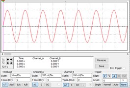
a) Sine wave
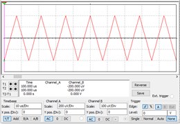
b) Triangle wave
c) Square wave
It can be seen from Fig. 8 that all system state of cases changes from a chaotic state to a large-scale periodic state, which can be detected by the Duffing CIS proposed in this study. This also shows that the circuit can be used to detect a variety of weak signals.
Fig. 8The results of Phase trajectories after inputting different signals
a) Inputting sine wave
b) Inputting triangle wave
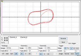
c) Inputting square wave
5. Conclusions
In this paper, the Duffing chaotic circuit module is designed for weak signal inspection in Multisim. All capacitors, resistors, amplifiers and other components in the circuit are accurately determined. Base on them, the Duffing equation in critical state with the group parameters is selected as Chaos Inspection System (CIS) of weak signal with strong noise. The solution of the circuit is basically consistent with that by Matlab. The accuracy of the circuit design is proved. In the simulation example, all of the sine wave, triangle wave and square wave can be successfully identified. In addition, the circuit also shows good noise immunity. This work provides a theoretical basis for the hardware of CIS of weak signal with strong noise.
References
-
C. Y. Nie, “Research on weak sinusoidal signalprocessing in time domain,” (in Chinese), Measurement technique, Vol. 5, pp. 3–5, 2000, https://doi.org/10.3969/j.issn.1000-0771.2000.05.001
-
A. Sharma, V. Patidar, G. Purohit, and K. K. Sud, “Effects on the bifurcation and chaos in forced Duffing oscillator due to nonlinear damping,” Communications in Nonlinear Science and Numerical Simulation, Vol. 17, No. 6, pp. 2254–2269, Jun. 2012, https://doi.org/10.1016/j.cnsns.2011.10.032
-
Y. N. Li, Y. Q. Fu, L. Yu, Y. W. Wang, and C. X. Liu, “FPGA Implementation for a DPSK digital receiver using duffing oscillators array,” in IEEE International Conference on Mechatronics and Automation (ICMA), pp. 1169–1173, 2018, https://doi.org/10.1109/icma.2018.848458
-
S. Y. Zhu, W. W. Hu, and Q. Wang, “Research on Duffing chaotic theory based nonlinear Lamb wave extraction and damage detection,” in Proceedings of the 40th China Control Conference, Vol. 8, pp. 367–371, 2021, https://doi.org/10.26914/c.cnkihy.2021.028688
-
R. Tian, Z. Zhao, and Y. Xu, “Variable scale-convex-peak method for weak signal detection,” Science China Technological Sciences, Vol. 64, No. 2, pp. 331–340, Feb. 2021, https://doi.org/10.1007/s11431-019-1530-4
-
L. Zhang, Y. Ji, and M. Luo, “Parameter estimation of weak signal based on the steady attractor of duffing oscillator,” Chinese Journal of Electronics, Vol. 28, No. 4, pp. 781–788, Jul. 2019, https://doi.org/10.1049/cje.2019.05.005
-
W. J. Sun, G. Rui, L. Wang, and W. B. Tian, “Estimation of weak signal phase by using Duffing-Vanderpol Oscillator,” (in Chinese), Telecommunication Engineering, Vol. 56, No. 1, pp. 14–19, 2016, https://doi.org/10.3969/j.issn.1001-893x.2016.01.003
-
A. Gokyildirim, Y. Uyaroglu, and I. Pehlivan, “A novel chaotic attractor and its weak signal detection application,” Optik, Vol. 127, No. 19, pp. 7889–7895, Oct. 2016, https://doi.org/10.1016/j.ijleo.2016.05.150
-
M. Akilli, N. Yilmaz, and K. Gediz Akdeniz, “Automated system for weak periodic signal detection based on Duffing oscillator,” IET Signal Processing, Vol. 14, No. 10, pp. 710–716, Dec. 2020, https://doi.org/10.1049/iet-spr.2020.0203
-
G. Li, Y. Hou, and H. Yang, “A new Duffing detection method for underwater weak target signal,” Alexandria Engineering Journal, Vol. 61, No. 4, pp. 2859–2876, Apr. 2022, https://doi.org/10.1016/j.aej.2021.08.016
-
Y. Li, W. Fan, and W. Huang, “The application of the duffing oscillator to detect electromagnetic leakage emitted by HDMI cables,” in 2021 IEEE International Joint EMC/SI/PI and EMC Europe Symposium, pp. 678–681, Jul. 2021, https://doi.org/10.1109/emc/si/pi/emceurope52599.2021.9559384
-
K. Srinivasan, K. Thamilmaran, and A. Venkatesan, “Effect of nonsinusoidal periodic forces in Duffing oscillator: Numerical and analog simulation studies,” Chaos, Solitons and Fractals, Vol. 40, No. 1, pp. 319–330, Apr. 2009, https://doi.org/10.1016/j.chaos.2007.07.090
-
W. W. Zhang, M. F. Cheng, and Z. L. Zhao, “Weak ultrasonic guided wave identification using Duffing system with periodic jump,” (in Chinese), Journal of Acta Acustica, Vol. 46, No. 4, pp. 605–613, 2021, https://doi.org/10.15949/j.cnki.0371-0025.2021.04.012
-
J. Wu, H. Hao, J. Li, Y. Wang, Z. Wu, and H. Ma, “Defect detection in pipe structures using stochastic resonance of Duffing oscillator and ultrasonic guided waves,” International Journal of Pressure Vessels and Piping, Vol. 187, p. 104168, Nov. 2020, https://doi.org/10.1016/j.ijpvp.2020.104168
-
Y. S. Wang, Z. C. Xiao, J. Sun, and H. D. Fan, “Simulation and experimental study on the chaos circuit of Duffing oscillator,” (in Chinese), Journal of Circuits and Systems, Vol. 13, No. 1, pp. 132–135, 2008, https://doi.org/10.3969/j.issn.1007-0249.2008.01.027
-
A. Buscarino, R. Caponetto, L. Fortuna, and E. Murgano, “Chaos in a fractional order duffing system: a circuit implementation,” in 2019 IEEE International Conference on Systems, Man and Cybernetics (SMC), pp. 2573–2577, Oct. 2019, https://doi.org/10.1109/smc.2019.8914007
Cited by
About this article

The work was supported by the National Natural Science Foundation of China (No. 11872261), the Key Laboratory of Robotics and Intelligent Equipment in General Universities of Guangdong Province (2017KSYS009), Dongguan Institute of Technology Supported by Robotics and Intelligent Equipment Innovation Center (KCYCXPT2017006).
