Abstract
Aiming at the requirements of Missile Radio Fuze Antenna with low sidelobe, narrow beam and specific directional pattern, a design method of Ka band substrate integrated waveguide (SIW) slot traveling wave array antenna is proposed. Based on the slot theory of SIW, the slot parameters and the excitation amplitude of Taylor linear array elements are calculated by MATLAB, and then the slot parameters and the excitation amplitude of array elements are optimized by Ansoft HFSS electromagnetic simulation software to realize the design of Ka band SIW slot traveling wave array antenna. The simulation results show that the Ka band SIW slot quasi traveling wave array antenna has a working frequency of 34.5 GHz, a gain of 14.2 dB, an E-plane beam width of 8° and a beam inclination of 20°, which can meet the requirements of missile radio fuze.
1. Introduction
Due to its special operation mode, Missile Radio Fuze often needs the antenna pattern of E-plane wide beam and H-plane low sidelobe narrow beam with specific direction [1-2]. The characteristics of rectangular metal waveguide slot array antenna meet the requirements of radio fuze, but its application range is limited due to its high processing cost, large volume and difficult to be conformal with the surface of projectile. SIW slot array antenna, as an alternative to the traditional rectangular metal waveguide slot array antenna, integrates the advantages of microstrip line and waveguide. It is mainly manifested in high efficiency, compact structure, light weight, small volume, easy integration and processing, etc. Moreover, the substrate integrated waveguide can better adapt to the surface mounted microwave and millimeter wave active devices that need coplanar circuit installation structure, which has important practical value and broad application prospects [3-4].
2. Theory of SIW slot antenna
2.1. Structure of SIW
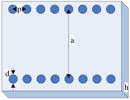
Substrate integrated waveguide (SIW) is a relatively new waveguide structure, which has similar propagation characteristics to the traditional rectangular waveguide. Its geometric structure is shown in Fig. 1. The upper and lower surfaces of the dielectric substrate are metal layers, and two rows of metallized through vias are set in the substrate. In this way, a structure similar to the dielectric rectangular waveguide is formed between the upper and lower metal surfaces and the two rows of metallized vias, which is called the substrate integrated waveguide. In the figure, a represents the distance between two rows of metal through vias, b is the width of substrate integrated waveguide, h is the thickness of dielectric substrate, d represents the diameter of metal through vias, and p is the distance between the centers of adjacent vias in metallized via array.
The main mode transmitted in the SIW is the TE10 mode, which can be replaced by an equivalent medium-filled rectangular waveguide for electromagnetic characteristic analysis. The substrate-integrated waveguide broadside is given by Eq. (1) [5]:
where:
Fig. 1Structure of SIW
2.2. Fed slot of SIW
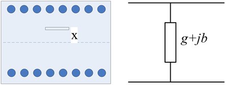
SIW can also form a linear array antenna fed by traveling wave or standing wave in the waveguide. The amplitude of gap excitation can be controlled by adjusting the offset of gap. When the slot cuts off the surface current on the waveguide wall, the electromagnetic field in the waveguide excites the slot, so that the energy in the waveguide is coupled to the free space and radiated out. The slot of substrate integrated waveguide does not cut the longitudinal current, but is only coupled with the transverse current. It can be regarded as an impedance or admittance element connected to the waveguide, so it can be represented by two terminal parallel elements [6]. The slot form and equivalent circuit are shown in Fig. 2.
Fig. 2Slot fed of SIW and its equivalent circuit
Based on the transmission line theory and the Green’s function of waveguide model, Stevenson derived the conductivity calculation formula of wide edge longitudinal gap [7]:
where, is the wavelength of free space, is the wavelength of waveguide, is the distance between the slot and the center line of the waveguide.
3. Simulation of SIW slot
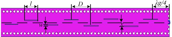
In order to obtain SIW slot array antenna with good electrical characteristics and pattern, its electrical parameters must be obtained very accurately, including slot width (), slot length (), slot spacing (), slot eccentricity () and slot array excitation amplitude distribution. The selection of slot width needs to consider the processing accuracy of the circuit board. The slot resonance length is approximately equal to half wavelength. The slot spacing is determined according to the beam direction, and the wide edge eccentricity needs to be determined according to the amplitude weight of the array segment.
Fig. 3Fed slot array antenna of SIW
Beam pointing formula [8] is as follows:
Then, the distance [9] of solts please refer to Eq. (8):
In this paper, a Ka band substrate integrated waveguide slot array antenna is designed. The working frequency is 34.5 GHz, the dielectric substrate is RT220F, the dielectric constant is 2.2 and the thickness is 0.508 mm. In the design, the dielectric filled rectangular waveguide is used to calculate the initial value, and then the substrate integrated waveguide parameters 6.5 mm, 0.8 mm, 1.2 mm are determined from Eq. (1). According to beam rake angle 19°, calculated by Eq. (8), gap spacing 3.92 mm. From the antenna gain of 14 dB, the number of slots is determined to be 16. Slot width 0.4 mm, slot length 4.3 mm, SIW slot array length is 62.78 mm. The slot array distribution adopts the Taylor weighted array distribution optimized by the improved genetic algorithm [10], and the excitation amplitude is shown in Table 1.
Table 1Slot array parameters weighted by Taylor distribution (unit: mm)
Weighted amplitude | Eccentricity | Weighted amplitude | Eccentricity | |
1 | 0.1791 | 0.3928 | 1.0000 | 1.0332 |
2 | 0.2555 | 0.4901 | 0.9433 | 0.9462 |
3 | 0.3874 | 0.6235 | 0.8393 | 0.9244 |
4 | 0.5448 | 0.7293 | 0.7016 | 0.8461 |
5 | 0.7016 | 0.8461 | 0.5448 | 0.7293 |
6 | 0.8393 | 0.9244 | 0.2555 | 0.6235 |
7 | 0.9433 | 0.9462 | 0.3874 | 0.4901 |
8 | 1 | 1.0332 | 0.1791 | 0.3928 |
Fig. 4 shows the 16-element SIW slot array antenna model established in Ansoft HFSS. The simulation pattern of the antenna is shown in Fig. 5 and Fig. 6, and the S-parameter curve is shown in Fig. 7.
Fig. 4Slot array antenna model of 16-element SIW
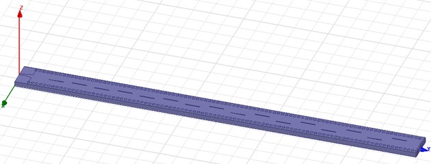
Fig. 53D radiation pattern curve of the 16-element SIW slot array antenna
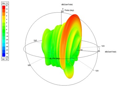
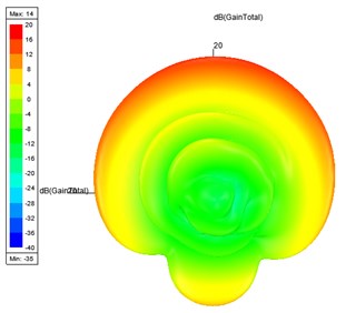
Fig. 62D radiation pattern curve of the 16-element SIW slot array antenna
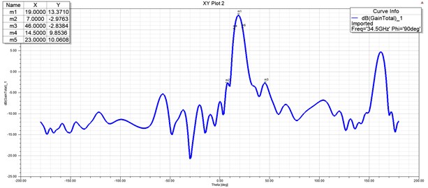
Fig. 7S-parameter curve of the 16-element SIW slot array antenna
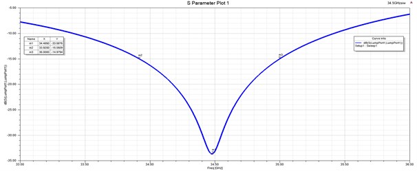
The simulation results show that the working frequency of the antenna is 34.5 GHz, the working bandwidth is 1 GHz with reflection less than –15 dB, the gain is 14.4 dB, the sidelobe level is –14.9 dB, the beam width of E-plane is 8°, and the inclination angle is 20°, which meets the design requirements. Moreover, when Ansoft HFSS based on finite element method simulates the designed slot array antenna, the coupling between each slot has been considered, and the result is close to the actual value. In engineering implementation, it is necessary to control the machining error and reduce the deterioration of antenna performance caused by machining accuracy.
4. Conclusions
In this paper, a simulation optimization design method of K-band SIW slot fed array antenna is proposed. Firstly, the initial value is calculated according to the working frequency and the dielectric filled rectangular waveguide, and the parameters of SIW are determined. The amplitude distribution, conductance and slot offset of Taylor linear array optimized by the improved genetic algorithm are calculated by MATLAB. Finally, the simulation is carried out by Ansoft HFSS. The simulation results show that the improved genetic algorithm is applied to the optimal design of K-band substrate integrated waveguide slot array, effectively controls the antenna sidelobe level, and realizes the working bandwidth of 1 GHz with reflection less than –15 dB, gain of 14.2 db, E-plane beam width of 8°, inclination of 20°, which meets the design requirements and meets the application requirements of missile radio fuze.
References
-
L. S. Zhang, Fundamentals of Fuze Principle. Xi’an: Xi’an Institute of Electromechnical Information Technology, 2021.
-
P. K. Malik, S. Padmanaban, and J. B. Holm-Nielsen, Microstrip Antenna Design for Wireless Applications. CRC Press, 2021.
-
J. Choi, J. Park, Y. Youn, W. Hwang, and W. Hong, “Frequency-reconfigurable mmWave antenna loaded with capacitive structure integrated within a microstrip line,” in 2019 IEEE International Symposium on Antennas and Propagation and USNC-URSI Radio Science Meeting, pp. 455–456, Jul. 2019, https://doi.org/10.1109/apusncursinrsm.2019.8888846
-
M. Ikram, N. Nguyen-Trong, and A. Abbosh, “Patch antenna array with continuous frequency and polarization tuning for 5G mid-band communications,” in 2019 IEEE International Symposium on Antennas and Propagation and USNC-URSI Radio Science Meeting, pp. 911–912, Jul. 2019, https://doi.org/10.1109/apusncursinrsm.2019.8888876
-
M. Z. Zheng, J. C. Zhao, and B. Li, “Design of multi-beam waveguide slotarray antenna based on SIW,” Fire Control Radar Technology, Vol. 39, No. 3, pp. 71–75, 2010, https://doi.org/10.19472/j.cnki.1008-8652.2010.03.017
-
V. Katyayani, N. S. Vahini, D. R. Krishna, and V. M. Pandharipande, “Design of Substrate Integrated waveguide slot array antenna at X-band,” in 2018 IEEE Indian Conference on Antennas and Propogation (InCAP), pp. 1–5, Dec. 2018, https://doi.org/10.1109/incap.2018.8770813
-
C. L. Lin, Antenna Engineering Handbook. Beijing: Publishing House of Electronics Industry, 2002, pp. 273–284.
-
W. Z. Lu, Antenna Theory and Technology. Xi’an: Xidian University Press, 2004, pp. 218–227.
-
O. U. Omini, D. E. Baasey, and S. A. Adekola, “Impact of element spacing on the radiation pattern of planar array of monopole antenna,” Journal of Computer and Communications, Vol. 7, No. 10, pp. 36–51, 2019, https://doi.org/10.4236/jcc.2019.710004
-
L. Shi, M. Z. Yan, Y. F. Li, Y. C. Zhao, and J. Ma, “The optimization design of millimeter wave waveguide slot array antenna base on improved genetic algorithm,” Journal of Detection and Control, Vol. 36, No. 1, pp. 71–75, 2014.
About this article

