Abstract
A novel design of traveling wave piezoelectric actuator with a special waveguide is investigated in the paper. Actuator consists of cylinder type waveguide and piezo ceramic ring. Waveguide has conical hole inside. Such configuration of the waveguide allows increasing amplitudes of the traveling wave vibrations. Electrodes of piezoceramic ring are divided into four equal sections. Four electric signals with shifted phases by 2 are used for the excitation. Numerical simulation was carried out to optimize the shape and dimensions of the waveguide and to maximize oscillation amplitudes at the contact surface of the waveguide. Mathematical model of the contact interface between stator and rotor was developed. A prototype piezoelectric actuator was made and experimental investigation was performed. Results of numerical and experimental investigation are discussed.
1. Introduction
Traveling wave motors are one of the most popular piezoelectric motors used in mechatronic systems during the last few decades. These type or motors are widely used for high precision mechanical systems such as positioning devices, manipulating systems, control equipment ant etc. Advantages of these motors are high resolution, short response time, and good controllability [1, 2]. These advantages give positive impact to developers so huge number of different design of the traveling wave actuators were proposed and used [3].
Traveling wave actuators can be classified as rotary type and linear type [3]. Rotary type actuators have the following advantages as high torque density at low speed, high holding torque, and quick response [4]. Linear type traveling wave actuators feature the same advantages but the development of these actuators is more complex [5, 6]. There are reports where authors introduce traveling wave ultrasonic motor of high torque. A new interaction type between stator and rotor was analyzed to achieve higher performance of ultrasonic motor [7]. Some authors analyze various hybrid vibrations of the stator to achieve higher performance of the traveling wave actuators [8, 9]. As for example a cylindrical traveling wave ultrasonic motor was proposed where superposition of three vibration modes i.e. first longitudinal, third bending and the sixth radial flexural vibrations was employed. However, the complicated structure and driving system of the motor makes it bulky and difficult to use for practical applications.
Proper regimes of the motor excitation give significant impact to the performance of the traveling wave motors. Therefore, various driving principles of the traveling wave motors were proposed. As for example, two different electrodes patterns for the electrodes excitation i.e. symmetrical and asymmetrical was proposed to generate traveling wave [10].
Rotary type traveling wave actuator with a novel waveguide is introduced in this paper. Waveguide is a cylinder with conical hole inside. The first longitudinal and second flexural vibration mode is used to obtain traveling wave vibrations on the top surface of the waveguide. Node of vibrations is shifting from the middle point of the waveguide length therefore displacement amplitudes are increased on the top surface of the waveguide.
2. Design and operating principle of piezoelectric actuator
Principle scheme of the investigated piezoelectric traveling wave actuator is shown in Fig. 1. Actuator consist of the piezo ceramic ring and aluminum cylindrical waveguide with conical hole inside. Piezo ceramic ring is glued at the bottom of the cylindrical waveguide using epoxy.
Fig. 1Principle scheme of piezoelectric traveling wave actuator
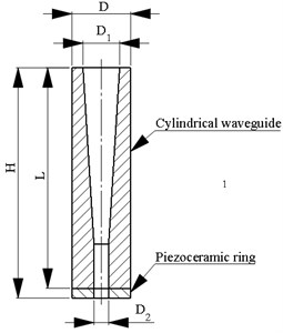
Fig. 2Excitation scheme of the actuator: 1 – multiphase harmonic signal generator with amplifier
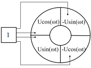
Topology of electrodes and excitation scheme of the actuator is shown in Fig. 2. Electrodes of piezoelectric ceramic ring are divided into four equal sections. Four sinusoidal signals with the different phase shifted by 2 are applied to the sections of electrode. Ground of the piezo ceramic ring is located in the opposite side of the ring.
Operation principle of the actuator is based on superposition of the first longitudinal and second flexural modes of the waveguide. Due to the achieved superposition of the two vibration modes, elliptical trajectory of motion will be generated on the top surface of the cylindrical waveguide. Special shape of the waveguide will ensure amplification of the vibration amplitudes at the top surface. Amplification is achieved because of the different stiffness of the actuator along it length. Therefore, node of the vibrations is shifted down from the center of the actuator and amplitudes of vibrations are increased at the top surface of the actuator.
3. Mathematical model of the contact interface between stator and rotor
Vibrations of the stator are converted into the rotary motion of the rotor because of contact friction. Characteristics of contact point motion, preload force and friction coefficient determine speed, torque and resolution of the motor. Contact model between stator and rotor was developed. It allows to predict characteristics of the motor and to analyze toque dependence from the preload, friction, geometrical and physical parameters. Principle scheme of the traveling wave actuator and spherical rotor used to build mathematical model is given in Fig. 3.
3DOF mechanical vibrations are excited in cylindrical waveguide in the common case by employing different excitation schemes of the piezoceramic ring. Vibrations of the waveguide are transferred into rotation of the spherical rotor therefore rotor rotates by the angle . Vector of the actuator vibrations in cylindrical coordinate system can be written as follows:
where , and are displacement in radial direction, rotation angle and displacement in axial direction respectively. Vector can be expressed in Cartesian coordinate system:
where is transformation matrix. System of dynamic equations of the actuator and rotor can be written as shown below:
here [], [], [], [] are matrices of mass, damping, stiffness and electroelasticity respectively; is a force vector generated by actuator under excitation of the electrical signal; is a contact force vector; [], [] are matrices of inertia moment and damping of the spherical rotor, respectively; is vector of rotor rotation; is a vector of electric potentials.
Fig. 3Principle scheme of the traveling wave actuator and rotor
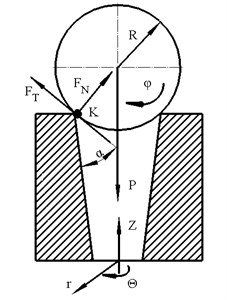
Contact force vector can be decomposed into two parts i.e. normal and tangential (Fig. 3). In this case torque of the spherical rotor obtained during one period of vibrations can be expressed as follows:
where is tangential component of the contact force, is radius of the rotor and is period of the vibrations. Tangential component of the contact force depends on the friction coefficient and direction of relative velocity and can be written as follows:
where is friction coefficient between actuator and sphere; is normal component of the contact force, is relative velocity between the contact point vibration velocity and the rotary speed of the rotor. It can be expressed as:
where is vibration velocity of the stator’s contact point. Value of the sign function depends on relative velocity and can be expressed as follows:
Friction coefficient is relevant to relative velocity and can be expressed as:
where is dynamic friction coefficient, is coefficient of the adhesion. Depending on the phases of the slipping and adhesion at the contact point, normal component of the contact force can be expressed as:
where is preload force, is contact stiffness coefficient of the contact point , is rotation angle force vector . Eq. (9) shows that during operation of the piezoelectric traveling wave motor there are two main phases: slipping and adhesion. Therefore, two cases can be analyzed i.e. and . Considering and substituting Eqs. (5), (8) and (9) into Eq. (4), the torque of the rotor can be expressed as:
When , equation of the torque has the following expression:
Analyzing expressions of the torque, it can be noticed that in order to increase torque of the motor friction coefficient, contact stiffness and preload force must be increased.
Let’s analyze efficiency of the motor by evaluating energy losses caused by friction on the contact surface between stator and spherical rotor during one period of stator vibrations. Friction loses on the contact surface can be divided into two components according to , coordinate axes:
here:
Output power of the motor during one period of the actuator vibrations can be expressed as:
Finally, the efficiency between the stator and rotor can be written as:
4. Numerical modeling and simulation of the actuator
Numerical investigation of the piezoelectric actuator was performed in order to validate actuator design and operating principle through the modal-frequency and harmonic response analysis. FEM model was built and simulation was performed employing Comsol Multiphysics 4.4 software. Properties of the materials used to build FEM model are given in Table 1. Isotropic loss factors were used for aluminum parts of the stator. Only electrical boundary conditions were set in the model i.e. voltage was set to 0 on the grounded electrodes. Actuator was simulated as mechanically not clamped system.
Table 1Properties of the materials
Material properties | PZT PIC181 | AW6082 aluminum alloy |
Density [kg/m3] | 7800 | 7710 |
Young’s modulus [N/m2] | 7.6·1010 | 7.1·1010 |
Poisson`s ratio | – | 0.33 |
Isotropic structural loss factor | – | 0.001 |
Relative permittivity | 1200; 1500 | – |
Elastic stiffness coefficient C33D, [N/m2] | 16.6·1010 | – |
Modal analysis of waveguide was performed in order to find natural frequencies of the first longitudinal and second flexural modes. These natural frequencies must coincide based on operating principle of the actuator, therefore corresponding dimensions of the waveguide must be defined. Wide range of parametric sweeps were performed in order to find suitable dimensions of the waveguide. Length of the waveguide was swept in the range from 30 mm to 60 mm with the step 1 mm while the upper diameter of the conical hole was swept in range from 4 mm to 11 mm with the step 1 mm. Lower diameter of the conical hole was fixed at 3 mm. The best geometrical parameters of the waveguide were found when the ratio of waveguide dimensions are equal to 0.03, 0.04 and 0.05. Particular dimensions of the waveguide are given in Table 2.
Table 2Dimensions of the waveguide
Parameter | 0.03 | 0.04 | 0.05 |
Diameter of the upper conical cavity base [mm] | 5 | 6 | 7 |
Diameter of the lower conical cavity base [mm] | 3 | 3 | 3 |
Length of the waveguide [mm] | 55 | 50 | 45 |
The best coincidence of the first longitudinal and second flexural mode frequencies occurs when ratio is equal to 0.05. In this case frequency of the first longitudinal mode is 58.5 kHz while frequency of the second flexural mode is 57.1 kHz. The differences between natural frequencies is 1.4 kHz. Modal shapes of the actuator are given in Fig. 3.
Harmonic response analysis was performed in order to find the trajectories of motion of the contact point at the resonant frequency. Frequency range from 54 kHz to 59 kHz with step 100 Hz was analyzed. Four electric sinusoidal signal with the phase shifted by 2 is applied to each section of piezoelectric ring (Fig. 2). Amplitude of the voltage was set to 100 V. Amplitude – frequency characteristic of the contact point is given in Fig. 4, where maximum displacement amplitude is 2.3 μm at 55.15 kHz.
Impedance – frequency characteristic was calculated (Fig. 6). Shape of the diagram confirms that the first longitudinal and second flexural modes are close i.e. difference of the resonant frequencies is 141 Hz. Finally, trajectories of the contact point motion were calculated in plane at the frequency 55.15 kHz when forward and backward excitation regimes are used (Fig. 7).
Fig. 4Modal shapes of the actuator: a) 1st longitudinal mode at 58.5 kHz; b) 2nd flexural mode at 57.1 kHz
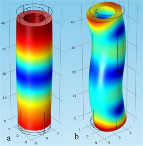
Fig. 5Displacement amplitude – frequency characteristic
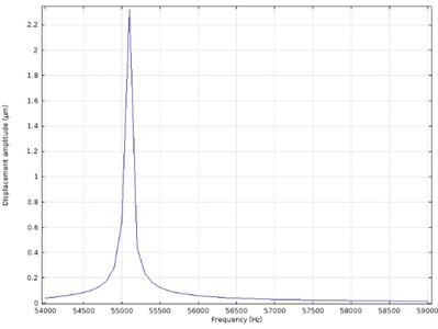
Fig. 6Impedance – frequency characteristics of the actuator
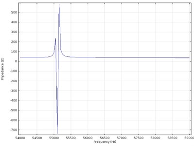
Fig. 7Trajectories of contact point motion
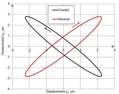
While analyzing the trajectories of the contact point motion, it can be noticed that they have ellipsoidal shapes. It confirms operating principle of actuator. The length of the ellipses is 7.12 μm and 7.03 μm when forward and backward excitation scheme is used. It must be mentioned that length of the ellipses of forward and backward motion are the same. Moreover, it must be noticed that the contact point moves in different directions when switching between excitation regime is performed. It confirms that two directional rotation of the motor will be obtained. Based on results of numerical investigation it can be concluded that operation principle of the traveling wave actuator with conical hole inside is confirmed. The actuator will produce bidirectional rotation at the 55.15 kHz frequency.
5. Experimental investigation
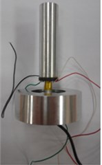
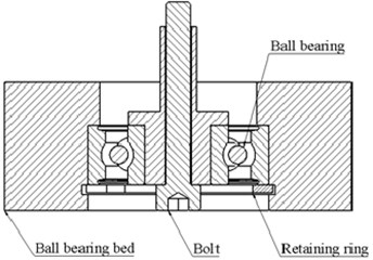
A prototype of the traveling wave actuator and special holder were made (Fig. 8). Holder of the actuator was designed to support actuator during experiments. Holder consist of conjunctive bolt, ball bearing bead, ball bearing and retaining ring. Ball bearing is used with intention to prevent unscrewing of the bolt during actuators operation.
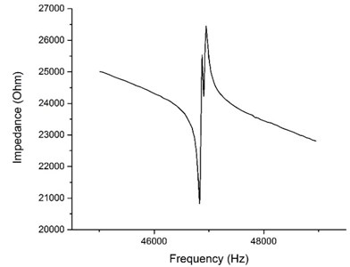
Firstly, impedance-frequency measurements were done in order to find resonant frequency of the actuator (Fig. 9). 4192A LF Impedance Analyzer (Hewlett Packard) was used. Frequency range was set from 45 kHz to 60 kHz during the first step of measurements. Obtained data was inaccurate, therefore new range was defined from 45 kHz to 49 kHz. Two peaks can be seen in the measured impedance graph (Fig. 9). They indicate the first longitudinal and second bending mode of the actuator. The resonant frequency was found at 46.95 kHz. The error between the measured and calculated resonant frequency of the actuator mainly came from FEM simulation, such as the inaccuracy of the material property parameters between the real and the simulated ones, not considering glue layer and the housing.
Fig. 8a) Traveling wave actuator with the holder and b) principle scheme of the holder
a)
b)
Fig. 9Impedance frequency characteristic of the actuator
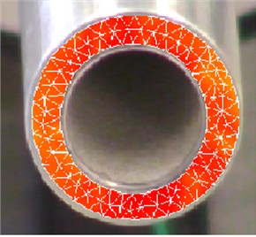
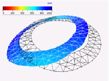
Next step of the experimental investigation was to measure oscillations of the actuator surfaces using vibrometer POLYTEC PSV 500. Investigation was performed in order to validate operation principle of the actuator. Measurements of the top surface oscillations of the waveguide confirmed that traveling wave oscillations are excited (Fig. 10). Moreover, resonant frequency of the actuator was determined at 47.14 kHz. Obtained resonant frequency value confirmed results of the impedance – frequency analysis.
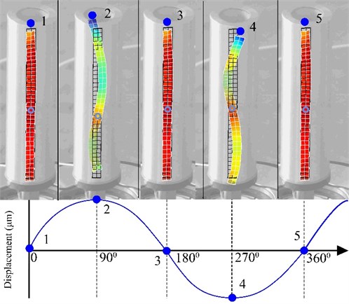
Distribution of the oscillation amplitudes along the length of the waveguide were measured as well. Measurements were performed in order to investigate longitudinal and flexural vibrations of the waveguide. Results of the measurements show position of the waveguide at each quarter of vibration period (Fig. 11). It can be seen that first longitudinal mode and second flexural mode are excited and that the contact point located at the top surface of the actuator has elliptical trajectory of motion. These measurements confirmed operating principle of the actuator. Vibration amplitude of the point 2 and point 4 are equal to 2.1 μm and 2.0 μm, respectively (Fig. 11). Difference between calculated and measured results is equal to 8.7 %.
Fig. 10Results of the oscillations measurements: a) mesh; b) distribution of the displacement amplitudes on the top surface of the waveguide
a)
b)
Fig. 11Measured distribution of the oscillations of the actuator
Next step of the experimental investigation was to measure dynamic characteristics of the actuator that is to obtain angular speed dependence from excitation voltage. Experimental setup was built for this purpose. Principle scheme of the setup is given in Fig. 12. It consists of function generator, amplifier, oscilloscope, reed switch, Atmega 328P microcontroller and personal computer. Reed switch was used to measure angular speed of the rotor. Reed switch was subdued as magnetically sensitive switch that rotor was equipped with the permanent magnet. Electrical signal was received because of interaction between the reed switch and permanent magnetic field. Time gap between two electrical signals was measured in order to calculate angular speed of the rotor. Special C code was developed for microcontroller to make measurements.
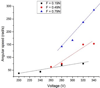
Measurements of the angular speed were made when preload force of the motor was 0,19 N, 0,49 N and 0,79 N. Results of the measurements are shown in Fig. 13. Analyzing results of the measurements it can be noticed that angular speed of the rotor increases when the excitation voltage increases. The largest angular velocity 281.3 rpm was obtained when preload force was 0.79 N and excitation voltage was 340 V. Also it must be noticed that angular speed of the rotor has almost linear dependence from the voltage therefore this actuator can controlled using simple and precise control system.
Fig. 12Principle scheme of the experimental setup: 1 – function generator; 2 – amplifier; 3 – oscilloscope; 4 – traveling wave actuator; 5 – reed switch; 6 – microcontroller; 7 – computer
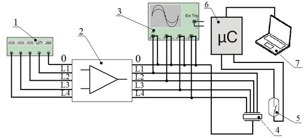
Fig. 13Dependence of angular speed of the rotor from excitation voltage
Heat generation is important problem that influence lifetime of the ultrasonic actuator. High temperature could lead to a degradation of piezoelectric material properties and indicates a low efficiency and short lifetime of the actuator. Heat is generated mainly because of contact friction losses, mechanical, dielectric and piezoelectric losses. Temperature of the traveling wave actuator was measured by employing FLIR SC7000 infrared camera. Actuator was driven under 150 V at 47.14 kHz. Ambient temperature was 20.7 °C. Temperature measurements were performed when preload force was 0.79 N. Total measurement time was during time was 1160 s. Results of the temperature measurements are given in Fig. 14.
Fig. 14Measured temperature of the actuator
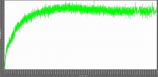
Analyzing results of the measurements, it can be seen that temperature increases exponentially during the first 300 s then reaches steady state temperature 21.3 °C. Temperature difference is equal to 0.6 °C. Low level of the actuator heating gives good opportunity to use actuator with higher excitation voltage and to obtain higher angular speed. Moreover, actuator with low heating characteristics has stable impedance – frequency characteristics and gives opportunity to have stable control and to use this actuator in high temperature environment.
6. Conclusions
A new traveling wave actuator with a special waveguide was developed. Proper dimensions of the actuator were found to achieve superposition of the first longitudinal mode and second flexural mode of the actuator. Numerical and experimental studies confirm possibility to achieve traveling wave oscillations at the top surface of the waveguide. Prototype actuator was made and maximum angular speed 281.3 rpm was obtained. Angular speed of the rotor increases with the increase of excitation voltage and depends on preload force. Measured temperature characteristic of the actuator confirmed that actuator has high temperature stability.
References
-
Uchino K., Giniewicz J. Micromechatronics. Marcel Dekker Inc., New York, 2003.
-
Bansevicius R., Barauskas R., Kulvietis G., Ragulskis K. Vibromotors for Precision Microrobots. Hemisphere Publishing Corporation, USA, 1988.
-
Zahao C. Ultrasonic Motors. Springer-Verlag, Berlin, Heidelberg, Germany, 2011.
-
Sashida T., Kenjo T. An Introduction to Ultrasonic Motors. Oxford Press, 1994
-
Uchino K. Piezoelectric ultrasonic motors: overview. Journal of Smart Materials and Structures, Vol. 7, 1998, p. 273-285.
-
Roh Y., Lee S., Han W. Design and fabrication of a new traveling wave-type ultrasonic linear motor. Sensors and Actuators A. Physical, Vol. 94, Issue 3, 2001, p. 205-210.
-
Chen Y., Liu Q. L., Zhou T. Y. A traveling wave ultrasonic motor of high torque. Ultrasonics, Vol. 44, 2006, p. 581-584.
-
Yang X., Liu Y., Liu W. C. J. A cylindrical traveling wave ultrasonic motor using bonded – type 4 composite beam. Ultrasonics, Vol. 65, 2016, p. 277-281.
-
Yun C. H., Ishii T., Nakamura K., Ueha S., Akashi K. A high power ultrasonic linear motor using a longitudinal and bending hybrid bolt-clamped Langevin type transducer. Japanese Journal of Applied Physics, Vol. 40, 2001, p. 3773-3776.
-
Mazeika D., Kulvietis G., Tumosoniene I., Bensevicius R. New cylindrical piezoelectric actuator based on traveling wave. Mechanical Systems and Signal Processing, Vol. 36, Issue 1, 2013, p. 137-135.
About this article
This work was supported by Research Council of Lithuania, Project No. MIP-045/2014.
