Abstract
This article represents a numerical and experimental investigation of a piezoelectric linear actuator with asymmetric design. The actuator is based on a square-shaped rod with asymmetrical cut and T-shaped clamping. The cylindrical rail, with slider, is on the opposite side of the T-shaped clamping. The low-volume and mass of piezoelectric actuator allows to mount it directly to printed circuit board (PCB). The actuator operation is based on the inertial stick – slip operation principle inducted by the first longitudinal vibration mode excited by two sawtooth signals with phase difference . Furthermore, the longitudinal vibration mode induces bending deformations of the rod, increasing the displacements of the cylindrical rail. The results of numerical and experimental investigations have validated the actuator operating principle, as well as shown that the displacement amplitudes of the guidance rail have reached 153.6 μm at the 200 Vp-p excitation signal amplitude, while the linear motion speed reached 45.6 mm/s at the same excitation signal.
1. Introduction
Today, modern mechatronic, aeronautic, and space systems are based on high-accuracy laser and optical devices driven by actuators and motors, while these drives must meet strict motion accuracy requirements [1]. However, during the development of these systems, the usage of electromagnetic actuators and motor becomes one of the most challenging aspects. Electromagnetic fields, limits in motion accuracy, scalability, and high mass become the main drawback of electromagnetic actuators and motors [2]. The best option to replace these drives are piezoelectric drives which overcomes electromagnetic in size, mass, scalability, and motion accuracy. Moreover, piezoelectric actuators and motors are able to provide magnetic-field-free operation, power free self-locking ability, and direct drive of load. Moreover, piezoelectric drives could be designed to drive the load angularly and linearly. However, in most cases, are more complex in design and drive [3]. Therefore, the most common piezoelectric drives are linear motion actuators which are based on the operation principle of inertial stick – slip. These types of actuators ensures the possibility to utilize all advantages of piezoelectric drives. However, there still exist demand for inertial linear piezoelectric actuators which are simple in design and have low mass and flexible mounting and driving possibilities.
Chen et al. reported on an inertial piezoelectric linear actuator based on dual discs [4]. Operation of the actuator based on inertial stick – slip principle which is obtained via simultaneously excited piezoelectric bimorph discs by a single rectangular excitation signal whose frequency was equal or close to the first bending mode of discs. This design ensures higher motion speeds and output forces at different amplitudes of the excitation signal. On basis of the results of numerical and experimental investigations, the authors claimed that the proposed actuator is capable provide of 37.5 mm/s speed and 15.4 mN of output force.
Ko et al. reported on a piezoelectric inertial linear actuator based on a bimorph piezoelectric disc whose operation is obtained via inertial slip - stick principle [5]. The actuator is based on single bimorph piezoelectric disc with a cylindrical rod mounted at the center of it and driven by sawtooth signal in order to excite the first, out of plane bending mode of disc. Due to usage of sawtooth signal, the disc slowly bends to one direction and rapidly bends to opposite, and by this way inertial operation principle is obtained. The authors, on basis of numerical and experimental investigations, found that the actuator is able to provide up to 15 mm/s of speed and 140 mN of output force.
This paper represents numerical and experimental investigations on piezoelectric linear motion actuator which operation is based on the inertial stick – slip principle. The actuator is based on a square-shaped rod with asymmetrical cut and T-shaped clamping. The operation principle of the actuator is based on the first longitudinal vibration mode of a square shaped rod excited by two sawtooth signals applied to eight piezo ceramic plates. The longitudinal vibrations of the rod are transferred to the rail through a thin wall, which is formed by an asymmetric cut. Moreover, during actuator operation in the first longitudinal mode, additional, in-plane, bending deformations occur due to asymmetric design of actuator. Therefore, in comparison to the state of art, the proposed actuator and its operation propose the possibility to obtain linear motion via excitation of the first longitudinal vibration mode in which displacements are amplified and transferred via thin wall, as well as due to the asymmetric design an additional bending mode of the rod is obtained which leads to higher motion speeds.
2. Design and operation principle of actuator
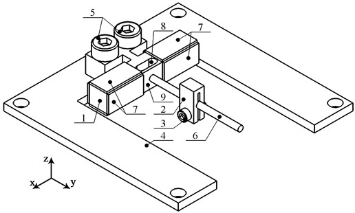
The piezoelectric linear actuator is made up of a square-shaped rod which contains asymmetrical cut and T-shaped clamping. The rod and clamp are made as one body from C17200 beryllium bronze. On the rod ends are glued plates made from NCE81 (CTS Corp, USA) hard piezo ceramic material. The polarization directions of piezo ceramic plates are pointed from a square-shaped rod. Asymmetrical cut, which is made in a square-shaped rod, forms a thin wall, while at the center of the wall a cylindrical guidance rail made of carbon fiber is placed, while on the rail, through friction force, a slider is placed. Finally, T-shaped clamping is used to mount the actuator to PCB via two M3 bolts. The design of the actuator is represented in Fig. 1.
Fig. 1Design of actuator: 1 - square-shaped rod; 2 – slider; 3 – bolt for slider clamping; 4 – printed circuit board; 5 – M3 bolts for actuator clamping; 6 – cylindrical guidance rail; 7 – piezo ceramic plates; 8 – asymmetrical cut; 9 – thin wall formed by asymmetrical cut
The operation of the actuator is based on the first longitudinal vibration mode of the square-shaped rod excited by two sawtooth signals with a phase difference in π. During vibrations, thin wall will be affected by two opposite forces inducted by the first longitudinal vibration mode and as a result will bend. Bending of the thin wall will ensure that longitudinal vibrations are transferred to the cylindrical guidance rail, and will amplify displacements of these displacements. In addition, the rod, during vibration in longitudinal direction, will generate bending, in plane, deformations which additionally improve displacement amplitudes of cylindrical guidance rail. Bending deformations are inducted due to uneven stiffness of the rod which is created by asymmetrical cut and clamping of the actuator. Therefore, the composition of excitation signal shape and structural design of actuator ensure the principle of inertial stick-slip operation.
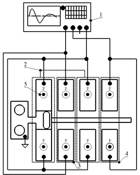
Excitation of the actuator is based on two sawtooth signals which are applied to piezo ceramic plates. In order to obtain proper operation, piezo ceramic plates must be divided to three separate groups, which ensures excitation of the first longitudinal vibration mode as well as enlarges bending vibrations. The actuator excitation schematics is given in Fig. 2.
The group of piezo ceramic plates dedicated to excite the first longitudinal vibration mode is composed from four piezo ceramic plates at the top and bottom of a square-shaped rod. The plates induct squeezing and stretching of the rod and by this way excites the first longitudinal vibration mode. The excitation signal for this group is not changed during the entire operation of the actuator. Groups dedicated to enlarge, in-plane, bending deformations are based on two piezo ceramic plates which are placed on sides of the rod. The excitation of these piezo ceramic plates is implemented by two sawtooth signals with phase difference in π in order to enlarge, in plane, the bending deformations of the rod, while one of the signals is the same as for the excitation of the longitudinal vibration mode.
Fig. 2Excitation schematics of actuator: 1 – excitation signal source; 2 – group of piezo ceramic plates used to excite longitudinal vibrations; 3 – group of piezo ceramic plates used to enlarge, in plane, bending of rod; 4 – group of piezo ceramic plates used to enlarge, in plane, bending of rod; 5 – polarization of piezo ceramics
3. Numerical investigation of actuator
Numerical investigations were performed to confirm operation principle, indicate the mechanical and electromechanical characteristics of the actuator. For this purpose, the finite element model (FEM) was built by COMSOL Multiphysics software. Boundary conditions were set as follows: the T-shaped clamping was fixed rigidly while electrical boundary conditions were set with respect to the schematic shown in Fig. 2 material characteristics were assigned as described in the previous section. The first stage of the numerical investigation was dedicated to modal analysis of the actuator. The goal of the investigation was to find the proper deformation mode and confirm its suitability for actuator operation. The results of the calculations are given in Fig. 3.
Fig. 3Modal shape of actuator at 59.72 kHz
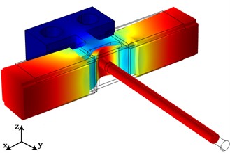
As can be found in Fig. 3, suitable modal shape of the actuator was obtained at 59.72 kHz. Also, the modal shape shows that the longitudinal vibration mode inducts, in plane bending deformations as well as thin wall bends under the effect of longitudinal displacements of the rod. Therefore, it can be concluded that vibration mode obtained at 59.72 kHz is suitable for actuator operation. The next stage of numerical investigations was dedicated to calculations of the impedance and phase frequency characteristics of the actuator. For this purpose, frequency domain study was set in range from 59.7 to 60 kHz with increment step of 5 Hz. The results of the calculations are shown in Fig. 4.
Fig. 4Impedance and phase – frequency characteristics of the actuator
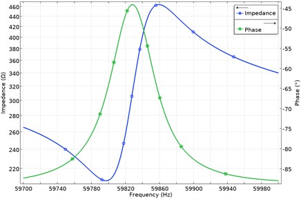
Fig. 5Displacement amplitudes of actuator in the y direction
As can be found in Fig. 4, the actuator resonance frequency is at 59.82 kHz. The slight mismatch between the values obtained by the modal and frequency domain studies is influenced by minor differences in the mesh as well as in the discreet steps used by the frequency domain study. However, the values are in good agreement and confirm the operation frequency of the actuator. In addition, the electromechanical coupling of the actuator was calculated and reached value of 0.045.
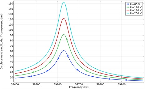
Finally, through a frequency domain study, displacement amplitudes were calculated at different amplitudes of the excitation signal in the direction. The goal of the investigation was to indicate the displacement amplitudes of the cylindrical guide rail inducted by vibrations of a square-shaped rod. The results of the calculations are given in Fig. 5.
As can be found in Fig. 5, the highest displacement amplitudes were obtained at 200 Vp-p and reached 153.6 μm or 768 nm/Vp-p while the lowest displacements were obtained at 80 Vp-p and reached 61.2 μm or 765 nm/Vp-p. It shows that the actuator is able to provide stable output displacements at different excitation amplitudes.
4. Experimental investigation of actuator
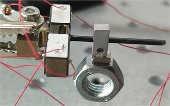
The prototype was made to perform experimental investigations and confirm the results of numerical calculations. The view of the prototype is shown in Fig. 6.
Fig. 6The prototype of the actuator
Firstly, impedance and phase frequency characteristics were measured in order to confirm the operation frequency of the actuator. The results of the measurements are given in Fig. 7.
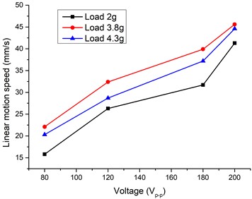
As can be found, resonance frequency of the actuator is at 59.45 kHz, which confirms results of numerical investigations. Minor difference in value is obtained as a result of slight mismatch in material characteristics as well as clamping. Finally, the linear motion speed was measured at different excitation amplitudes, as well as with different loads. The results are given in Fig. 8.
As can be found in Fig. 8, the highest linear motion speed was obtained at 200 Vp-p while the load was 3.8 g and reached 45.6 mm/s or 0.228 mm/s/Vp-p while the lowest motion speed at this load value was obtained at 80 Vp-p and reached 22.1 mm/s or 0.276 mm/s/ Vp-p. In general, the graph shows that the actuator is capable of providing stable and predictable motion speed at different load and excitation signal parameters.
Fig. 7Impedance and phase frequency characteristics of the actuator
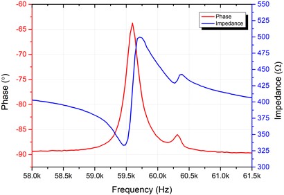
Fig. 8Linear motion speeds at different load and excitation signal amplitudes
5. Conclusions
Novel asymmetrical design of piezoelectric inertial linear motion actuator introduced and investigated. The actuator ensures the possibility to generate linear motion via inertial stick – slip operation principle inducted by the first longitudinal vibration mode of the stator while the asymmetric design of it increases displacement amplitudes and as a result linear motion speeds. Numerical investigations have shown that asymmetrical design of actuator inducts additional bending deformations of stator which allows to obtain higher motions speed while thin wall, which is formed by asymmetrical cut, acts as vibrations amplifier. Experimental investigations confirmed results of numerical investigations and have shown that the linear motion speed generated by the actuator reaches 45.6 mm/s while the amplitude and load of the 200 Vp-p and 3.8 g excitation signal are applied to the actuator.
References
-
S. Affan Ahmed, M. Mohsin, and S. M. Zubair Ali, “Survey and technological analysis of laser and its defense applications,” Defence Technology, Vol. 17, No. 2, pp. 583–592, Apr. 2021, https://doi.org/10.1016/j.dt.2020.02.012
-
S. Khalid, F. Khan, B. Ullah, Z. Ahmad, and S. Akbar, “Review of moving magnet linear oscillating actuators for linear compressor application,” World Journal of Engineering, Apr. 2022, https://doi.org/10.1108/wje-08-2021-0473
-
S. Mohith, A. R. Upadhya, K. P. Navin, S. M. Kulkarni, and M. Rao, “Recent trends in piezoelectric actuators for precision motion and their applications: a review,” Smart Materials and Structures, Vol. 30, No. 1, p. 013002, Jan. 2021, https://doi.org/10.1088/1361-665x/abc6b9
-
W. M. Chen, C. H. Chan, and T. S. Liu, “The Study of a dual-disk type piezoelectric actuator,” Mathematical Problems in Engineering, Vol. 2013, pp. 1–10, 2013, https://doi.org/10.1155/2013/108912
-
H.-P. Ko, K.-J. Lee, K.-H. Yoo, C.-Y. Kang, S. Kim, and S.-J. Yoon, “Analysis of tiny piezoelectric ultrasonic linear motor,” Japanese Journal of Applied Physics, Vol. 45, No. 5B, pp. 4782–4786, May 2006, https://doi.org/10.1143/jjap.45.4782
About this article

This research was funded by the Research Council of Lithuania according to the activity “Postdoctoral fellowships studies” under funding agreement No. S-PD-22-18.
The datasets generated during and/or analyzed during the current study are available from the corresponding author on reasonable request.
The authors declare that they have no conflict of interest.
