Abstract
Piezoelectric vibratory conveyors are widely used in many industrial fields such as factory automation. However, there is still a limitation for most cases that the vibratory conveyor can only feed in the designed direction. In today's multitasking intelligent machinery, how to sort different parts from the same feed source and convey them efficiently in different directions remains a challenge to be overcome. This study proposes an innovative design that uses a composite sinusoidal control signal to drive a linear two-stage piezoelectric vibratory feeder. By simply tuning the amplitude and phase of the input composite signal, the conveying velocity and direction can be altered easily. The dynamic characteristics of this feeder were both investigated by theoretical formulation and experimental measurement. It is found that the conveying performance of this feeder is better suited for using the composite signal with two sinusoidal components of double frequency. With the composite control signal synthesized by two sinusoidal components of 237.5 Hz and 475.0 Hz, which were close to the feeder’s first two resonance frequencies to increase the response gain of the structure, and the input voltage of 60 V, which corresponded to the trough’s displacement amplitude of 54.5 m, the measured conveying speeds were +30.8 mm/s and –33.3 mm/s for setting the phase angles 180° and 0°, respectively. The result demonstrates the feasibility of the proposed two-way vibratory feeder design.
Highlights
- A two-way linear vibratory feeder controlled by a composite sinusoidal input function is simple to operate.
- Composite sinusoidal input function with two double frequency components is more effective in driving.
- Both conveying velocity and direction can be tuned by controlling voltage and phase of input function.
- Only one set of piezoelectric actuators is required in operation.
1. Introduction
Vibratory feeders have been widely applied in industry for years. They deliver parts in sequential fashion to the desired location with high efficiency and screening capability [1]. A simple function as they might serve, they are indispensable equipment for factory automation of various industries [2], which include machinery assembling, sorting and inspection of the electronic components, particulate transportation for food and agricultural industry, etc. [3, 4]. These vibratory feeders can be categorized as spiral bowl and linear types according to their feeding paths, or electromagnetic and piezoelectric types based on their motion driving actuators used. Although the feeders with electromagnetic drivers [5, 6] are usually high in driving power and transportation capability [7], they often suffer from the shortcomings of bulky in size, complicated in mechanical design, noisy in operation, and susceptible to magnetization for metallic parts. On the other hand, piezoelectric vibratory feeders [8-17] are compact in size, less heat and noise generation in operation, less power consumption and lower collateral influence to the conveyed parts. Recently, miniaturization of product design prevails in the technological development such as the application of micro-electro-mechanical system (MEMS) and semi-conductor technology [16]. How to prevent these fragile parts from collision and damage during conveying is an essential issue. Delicate controllability of the piezoelectric vibratory feeders renders them more preferable in the competition.
The industrial piezoelectric vibratory feeder first appeared in Japan in 1970s [8]. There have been many improvements in design and performance since then. Both spiral bowl [9-12] and inline (linear) [13-17] types retrofitted with piezoelectric actuators emerged. For the linear vibratory feeder, Hsieh and Shih [13] proposed a design incorporating a Scott Russell linkage which was driven by a piezoelectric stack actuator. The length of its leaf spring could be adjusted in order to align its fundamental frequency with that of utility power source. Thus, electric power from the grid could directly drive the feeder in resonance and the electronic devices required for ordinary signal preprocessing became redundant. Similar design driven directly by utility power grid was also reported by Rade and coworkers [14] with the replacement of stack actuator by piezoelectric patches.
Although the mass of the conveyed part is usually much smaller than the feeder platform and has little influence on the conveying performance, Choi and Lee [9] studied the influences of part, input voltage and frequency on the conveying velocity of a piezoelectric bowl feeder. Nevertheless, in most studies, the influence of the mass inertia effect of the parts on the dynamics of the feeder is usually neglected. Regarding the modeling of piezoelectric vibratory feeders, the discrete lumped model [10-12] and continuum model [15, 17] were adopted by researchers, respectively. Since the vibratory feeder is always operated near its natural frequency to reduce the mechanical impedance, dynamic modeling for finding the natural frequency of the feeder [9-15] is an essential task in the design process. Hu and coworkers [16] proposed a linear vibratory feeder driven by bimorph piezoelectric patch with non-sinusoidal control voltage waveform to decouple the axial and transverse motions of the trough and minimize the possible damage to the conveyed parts. However, because of the non-uniform impedance of the feeder structure with respect to different frequencies, an inversion based control was required to compensate the possible distortion of the waveform. This raised the complexity in the controller design.
In the various applications of vibratory feeders, some have the capability of changing conveying direction upon control. One typical application of the two-way vibratory feeder is on the foundry operations. Castings can be delivered to the feeder or conveyor intermediate its either end as required [18]. Initial design incorporating vibration absorbers in inclined angle arrangements can be selectively tuned to damp out the elliptical motion of the trough in one angle and retain the other. The remained elliptical motion caused the trough to convey the parts in the controlled direction [19]. The design was further improved by moving the vibration absorbers to both supporting ends and employing only one eccentric mass driven by one electrical motor [18]. It is essential that the trough was moving in a horizontally elongated elliptic trajectory in order to reduce the vertical collision and noise during operation [20]. However, those designs with direction control involved the change in rotation direction of the motor. Thus, it was not responsive quickly to the required alteration in conveying direction. Frei [21] proposed a novel vibratory conveyor which was able to control the conveying in the desired direction on a horizontal platform. For a conveying platform array with n units of this design, only actuators were needed. However, for simple application in single unit it still required two actuators instead of one in conventional design. Moreover, the control of phase angle between two actuators also required special attention.
In this study, a new design of linear vibratory feeder driven by industrial piezoelectric actuator is proposed with the goal to simplify both the mechanical design and the electrical control. The change in conveying direction and velocity can be simply controlled by tuning the phase angle in a composite sinusoidal input voltage. The design process and the performance of this two-way linear vibratory feeder are studied.
2. Theoretical formulation
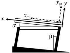
Fig. 1 presents the schematic diagram of a conventional linear vibratory feeder which operates in conveying parts to the left. In this configuration, and are the inclined angles of the trough and the leaf spring with respect to the horizontal and vertical axes, respectively. Moreover, and denote the coordinates of the trough while and represent those of the conveyed part. In the conveying process, the part may move with the trough, slide on the trough, or fly over the trough depending upon the dynamics of motion [22]. In this study, for the two-way conveying to be feasible, a horizontal trough with vertical leaf spring support, i.e. 0°, was selected as the basic configuration. Therefore, only horizontal coordinate components of the trough and part, and , exist and remain zero. Without possible separation of the part from the trough, no subsequent collision between them will happen. Thus, noise and possibility of damaging the fragile part in conveying can then be reduced.
Fig. 1Schematic diagram of a conventional linear vibratory feeder with inclined trough
During motion of the part on the trough, relative sliding can occur if the following condition hold:
Then:
Otherwise, the part moves together with the trough, i.e.:
In the above equations, denotes the coefficient of friction, represents the tolerance in numerical calculation and sgn(·) stands for the sign function.
For industrial applications, it would be easier to drive the electrical devices with sinusoidal signal. Thus, a composite sinusoidal function in the following form is proposed:
Basically, the composite function consists of two sinusoidal components which have different circular frequencies and , a gain ratio and a phase difference between them. The gain ratio is to consider the possible difference in the feeder’s structural response to same excitation amplitude at different frequencies and . For a given input function of Eq. (4), the output displacement of the part can be calculated by a step by step numerical integration of Eqs. (2) or (3) with respect to time. At each time step, whether the part slips is determined by using Eq. (1).
As an example, to see the influence of the phase angle , with following parameters is simulated: 10 mm, 100 Hz, , 1.0 and 0°. The selection of only as multiples of is to retain as a standing wave which is stable in time activation. The results with 2, 3 and 4 are shown in Fig. 2. It can be seen that the periodic within each cycle increased its oscillation frequency as was raised. The more frequent change in oscillation direction shortened the acceleration or deceleration time interval. Moreover, the sliding force transmitted through friction to drive the part was limited by the constant kinetic friction. The shorter the driving interval, the lower the part’s velocity. This can be shown more obviously in the following simulation. Furthermore, it can be seen as , that the nearly symmetric oscillation of the trough in back and forth directions was not constructive in conveying the part. However, it must be mentioned that the alteration in phase angle can change the wave form of the input function and, consequently the conveying performance of the feeder.
Fig. 2The simulated input displacement functions with A= 10 m, ω1= 100 Hz, ω2=nω1, G= 1.0 and ϕ= 0°
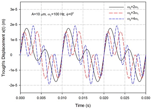
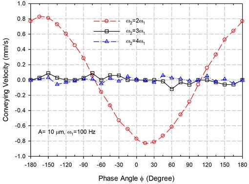
Using the assumed displacement function of the trough with different phase angles , the calculated displacements of the part are shown in Fig. 3. It is clearly seen in the result of that although the trough moved periodically, the part could be overall conveyed in different velocities and directions. This result reveals theoretically that by simply tuning the phase angle in Eq. (4), the part can be conveyed in either direction with different velocities. It must be reiterated that although the can be chosen as any multiple of to preserve the periodicity of the input function, is more efficient in terms of raising the conveying velocity, as shown in simulation results of Fig. 3. Moreover, higher frequency is usually more difficult to excite in structural vibration. Therefore, only the design with is investigated afterwards in this study.
Fig. 3The calculated output displacements of the conveyed part under input displacement functions with A= 10 m, ω1= 100 Hz, ω2=nω1, G= 1.0 and different phase angles
3. Mechanical design
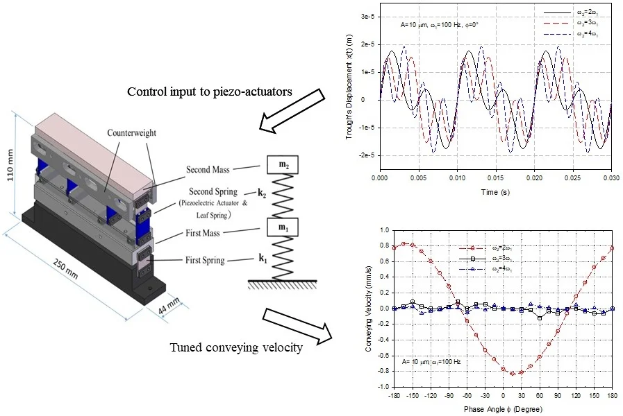
In ordinary design of vibratory feeders, the excitation frequency is usually chosen near its structural natural frequency to amplify the displacement gain. For having the two-way conveying characteristics, the vibratory feeder must be symmetric with respect to its mid-span. Otherwise, the driving performance will be different in one direction from the other. Moreover, the proposed feeder is to be excited with two distinct frequency components as seen in Eq. (4). A design configuration with two stages suspended on top of leaf springs is therefore presented in Fig. 4. The base at bottom of this feeder was employed as a foundation to be bolted down on a test bench. Two first-stage leaf springs connected the base and the first stage block. Between the first and the second stage blocks there were four piezoelectric actuators, each connected in series with a second-stage leaf spring, to support the trough on the first stage. On the sides of each stage block, additional mass block could be attached if it is necessary to tune the system’s natural frequencies. It should be mentioned that all four piezoelectric actuators formed one set of actuators which were driven by the same input voltage source.
Fig. 4Assembly drawing and simplified mathematical model of the linear vibratory feeder used in this study
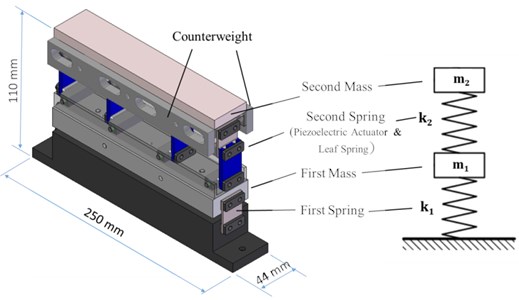
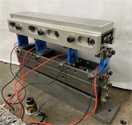
Fig. 5 shows the picture of the piezoelectric actuators employed in this study. The actuators were manufactured by Changzhou Piezoceramic Co., China, for vibratory feeders in industrial application. The picture of the assembled vibratory feeder used in this study is also presented in Fig. 6. With the structural configuration presented in Fig. 4, this vibratory feeder was simplified as a 2-DOF discrete mathematical model with the equivalent masses and spring constants calculated from the parameters and material properties of its components. Theoretical formulation in the following section could provide a preliminary estimation of the first two natural frequencies of the feeder in the early design phase.
Fig. 5The piezoelectric actuator (Piezosale CN-2443) used in this study and its assembly with a leaf spring
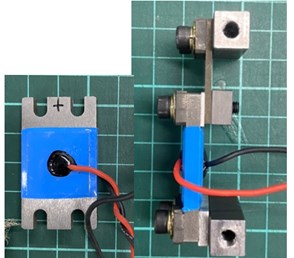
Fig. 6The picture of the assembled vibratory feeder used in this study
4. Theoretical formulation
The leaf spring of the first stage can be assumed to be fixed and subjected to parallel transverse loading at both ends. According to the deflection of a wide beam, the equivalent spring constant of the first stage in the theoretical model can be written as:
where the Young’s modulus 200 GPa, Poisson’s ratio 0.3, area moment of inertia 1.17×10⁻¹¹ m4, length of the spring 25 mm. Those dimensions and material properties give rise to 1.609 kg and 3.938×10⁶ N/m for the first stage of the feeder model. As seen in Fig. 5, the equivalent spring of the second stage was the series connection of a piezoelectric actuator and a leaf spring. With similar boundary condition and loading of the first stage, the derivation of the equivalent spring constant for the second stage results in:
where the Young’s modulus 200 GPa, Poisson’s ratio 0.3, area moment of inertia of the piezoelectric actuator segment 1.28×10⁻¹⁰ m4, length of the piezoelectric actuator segment 33 mm, area moment of inertia of the leaf spring segment 1.60×10⁻¹¹ m4, length of the leaf spring segment 20 mm. Those dimensions and material properties give rise to 0.822 kg and 4.086×10⁶ N/m for the second stage of the feeder model. With the obtained parameters of the theoretical model, the natural frequencies can be calculated following the formula given by standard textbook of mechanical vibration [23].
5. Electrical driver for the piezoelectric actuators
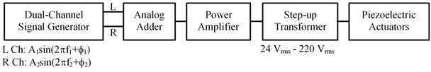
Fig. 7 presents the schematic diagram of the driving circuit for the piezoelectric actuators used in this vibratory feeder. The input function described in Eq. (4) can be divided into two components supplied synchronously by a dual-channel signal generator. These two components are added up, amplified in power, and raised in voltage before it is used to drive the piezoelectric actuators. There were four piezoelectric actuators installed and connected in parallel to the electrical driving circuit for this vibratory feeder. If the required power output is low, it is theoretically sufficient to drive only some of the actuators.
Fig. 7The schematic diagram of the electrical driving circuit for the piezoelectric actuators used in this vibratory feeder
6. Results and discussion
6.1. Dynamic properties of the feeder
Experimental measurement using impulse technique was performed and the response spectrum was obtained. Fig. 8 presents the autospectrum of the feeder measured from an accelerometer mounted on the second-stage block (trough) while subjected to an impulse from an impact hammer at the same mass block. The frequency spectrum shows the resonance frequencies of the feeder’s first two modes. It is seen that the feeder had the second mode’s frequency nearly double of its first one. More importantly, two resonance peaks had more or less the same acceleration gains. The same gain at two resonance frequencies would facilitate the excitation of the response at two frequencies described in Eq. (4), without one being overshadowed by the other. Table 1 lists the comparison between the first two modes’ natural frequencies obtained by theoretical formulation and experimental measurement. Apparently, the theoretical formulation still had 20 % discrepancy with the measurement ones. However, considering the simplification of the bolted joints as perfect junction and the omission of mass from the bolts, nuts, and other miscellaneous parts, the theoretical formulation could still serve as a reliable preliminary estimation in the design of the feeder’s dynamic properties.
Fig. 8The measured autospectrum of the fabricated vibratory feeder
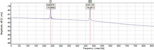
Table 1The first two natural frequencies of the fabricated vibratory feeder determined from theoretical formulation and experimental measurement.
Mode | Experiment (Hz) | Theoretical formulation (Hz) | Percentage error |
1st | 239.4 | 190.0 | –20.6 % |
2nd | 478.1 | 464.7 | –2.8 % |
Fig. 9The change in resonance frequencies of the vibratory feeder with the displacement amplitude of excitation measured at the trough
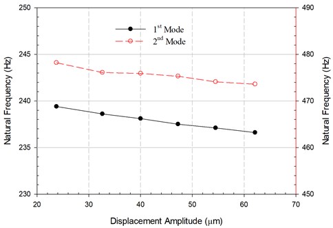
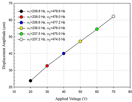
Because it was very difficult to have all the bolted joints being fixed as perfect bonding, the boundary conditions of the leaf springs and the piezoelectric actuators exhibited certain degree of nonlinearity [24]. The joint stiffness reduced slightly as the vibration amplitude increased. Accordingly, the resonance frequencies of the vibratory feeder decreased with increasing displacement amplitude of the trough, as seen from the measured results presented in Fig. 9. Although these frequency changes were less than 1.5 % within the range of displacement amplitude studied, the response gain lowered quite drastically off the resonance peak, as observed in Fig. 8. This drift in the dynamic property of the vibratory feeder at different excitation amplitudes could seriously reduce the effectiveness of the input excitation because of the quick drop in response away from the resonance frequency. Thus, the excitation frequencies had to be adjusted according to the control voltage input to the piezoelectric actuators. If these nonlinear characteristics of the vibratory feeder were taken into account, the results in Fig. 10 show that the vibratory displacement amplitude of the trough can be controlled linearly with the input voltage.
Fig. 10The measured displacement amplitude at the trough with the raise in control voltage applied to the piezoelectric actuators
6.2. Coefficient of friction
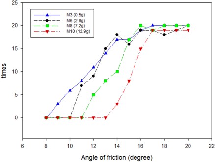
The coefficient of friction between the aluminum trough and the stainless bolt was obtained by measuring its angle of repose. Repeated tests of angle of repose were performed by placing different sized bolts on the trough and raising its inclined angle gradually until the bolt slid down. Fig. 11 presents the counts of bolts slid down the aluminum trough at different inclination angles. It was found that for four different bolts during 20 tests all slid down the trough when the inclination angle reached 17°. According to the definition of angle of repose, the coefficient of friction between the stainless bolts and the aluminum trough was found to be 0.31 (tan17°). Apparently, this coefficient of friction was barely influenced by the mass or size of the bolts.
Fig. 11The counts of bolts slid down the aluminum trough at different inclination angles
6.3. Control of conveying velocity and direction
As seen in Fig. 3, the feeder theoretically can have fast conveying velocity as the phase angle in the composite sinusoidal signal is set to be near 0° and 180°. Therefore, the conveying velocity of the manufactured feeder at these phase angles were measured at different acceleration amplitudes of vibration excitation, which were obtained by adjusting the control voltage. The conveying velocity was calculated by dividing the length of the trough with the measured time required for the part to transmit from one end to the other. Fig. 12 presents the measured conveying velocities along with the those results from simulation of the theoretical formulation. The velocity increased more or less linearly with the raise in acceleration amplitude. With the acceleration amplitude reached 220 m/s2, which corresponded to the applied voltage of 60 V, the obtained conveying velocities were near 30 mm/s and 33 mm/s in opposite directions. Those simulation results correlated well with measured ones.
Fig. 12The conveying velocities of the proposed vibratory feeder controlled by the acceleration amplitude of the trough under composite sinusoidal signals with two different phase angles ϕ= 0° and 180°
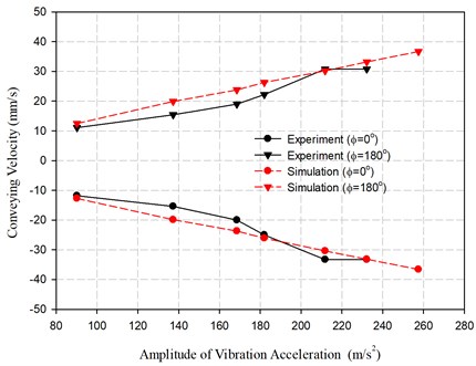
Fig. 13The change in conveying velocities of the proposed vibratory feeder with respect to the phase angle ϕ activated at control voltage of 30 V and ω1= 239.0 Hz, ω2= 478.0 Hz
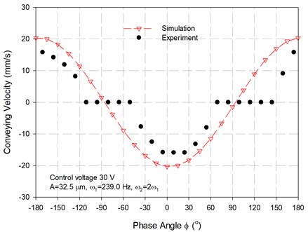
Furthermore, Fig. 13 shows the results of conveying velocity as the phase angle changed under fixed control voltage (30 V) and frequencies 239.0 Hz, 478.0 Hz). The simulation result demonstrates a more sinusoidal change in conveying velocity with respect to the phase angle. Measured results basically presented a similar trend with the simulation ones but more deviation occurred at lower conveying velocity. At low conveying velocity, the friction coefficient may be more critical in controlling the conveying velocity. The variation in the measurement of friction coefficient as observed in Fig. 11 could contribute this larger discrepancy. Nevertheless, both maximum forward and backward conveying happened at 0° and 180° were consistent with the previous finding. All these results confirmed the feasibility of obtaining a two-way vibratory feeder with the control of voltage and phase angle to tune its conveying velocity and direction.
7. Conclusions
With the proposed two-stage configuration driven by piezoelectric actuators without any inclined angles in leaf springs and trough, a two-way controllability of a vibratory feeder via input voltage and phase angle of the composite sinusoidal signal was demonstrated. In order to amplify the structural response, the structure of the feeder was designed to have its second natural frequency as double of its first one and the feeder was driven in vibration near its natural frequencies. At the control voltage of 60 V, a conveying velocity around 30 mm/s was able to switch direction by simply change the phase angle of the composite sinusoidal signal from 0° to 180°. The pure sliding of parts on the trough was able to minimize the possible damage to the fragile parts during conveying. Moreover, only one set of piezoelectric actuators with simply control parameter settings make this design easily applicable to industrial applications. The array assembly of this two-way feeder unit can be feasibly applied in more sophisticated sorting and conveying of assorted parts in the future.
References
-
Boothroyd G. Assembly Automation and Product Design. 2nd Ed., CRC Press, 2005.
-
Maul G. P., Thomas M. B. A system model and simulation of the vibratory bowl feeder. Journal of Manufacturing Systems, Vol. 16, Issue 5, 1997, p. 309-314.
-
Goncharevich I. F., Frolov K. V., Rivin E. I. Theory of Vibratory Technology. Hemisphere Pub. Corp, New York, 1990.
-
Fayed M. E., Skocir T. S. Mechanical Conveyors: Selection and Operation. CRC Press, 1996.
-
Ding X., Dai J. S. Characteristic equation-based dynamics analysis of vibratory bowl feeders with three spatial compliant legs. IEEE Transactions on Automation Science and Engineering, Vol. 5, Issue 1, 2008, p. 164-175.
-
Mucchi E., Di Gregorio R., Dalpiaz G. Elastodynamic analysis of vibratory bowl feeders: modeling and experimental validation. Mechanism and Machine Theory, Vol. 60, 2013, p. 60-72.
-
Yandrick R. Vibratory feeders and conveyors- useful selection tips. Chemical Engineering, 2009, p. 47-49.
-
Aoki N. Piezoelectric parts feeder system and its applications. Automatics, Vol. 21, Issue 2, 1988, p. 48-56, (in Japanese).
-
Choi S. B., Lee D. H. Modal analysis and control of a bowl parts feeder activated by piezoceramic actuators. Journal of Sound and Vibration, Vol. 275, 2004, p. 452-458.
-
Sun Z., Jiang L., Xiao W. The model and experimental study of spiral piezoelectric vibration feeder. IEEE 16th International Conference on Communication Technology, 2015.
-
Su J., Shen Y. H., Yang Z. G. Research of vibratory feeder activated by the bimorph vibrator. Applied Mechanics and Materials, Vol. 483, 2013, p. 342-346.
-
Long Z., Shen H., Zhang J., Zhao S., Lin Y., Li Z. Dynamics model and vibration control of piezoelectric feeder in semiconductor manufacturing assembly. IEEE Transactions on Semiconductor Manufacturing, Vol. 31, Issue 1, 2018, p. 97-107.
-
Hsieh W. H., Shih N. N. On an inline conveyor resonantly driven by piezoelectric actuators. Journal of Vibroengineering, Vol. 16, 2014, p. 2164-2170.
-
Rade D. A., De Albuquerque E. B., Figueira L. C., Carvalho J. C. M. Piezoelectric driving of vibration conveyors: an experimental assessment. Sensors, Vol. 13, 2013, p. 9174-9182.
-
Chao P. C., Shen C. Y. Dynamic modeling and experimental verification of a piezoelectric part feeder in a structure with parallel bimorph beams. Ultrasonics, Vol. 46, Issue 3, 2007, p. 205-218.
-
Hu Z., Maul G. P., Farson D. Piezo actuated vibratory feeding with vibration control. International Journal of Production Research, Vol. 45, Issue 5, 2007, p. 1089-1100.
-
Ting Y., Jar H. C., Lin C. Y., Huang J. S. A new type of parts feeder driven by bimorph piezo actuator. Ultrasonics, Vol. 43, Issue 7, 2005, p. 566-573.
-
Musschoot A. Two-Way Vibratory Feeder or Conveyor. U.S. Patent No. 5713457, 1998.
-
Schrader P. H. Reversible Vibratory Feeder. U.S. Patent No. 3746149, 1973.
-
Musschoot A. Two-Way Vibratory Feeder. U.S. Patent No. 6705459B1, 2004.
-
Frei P. U. Theory, design and implementation of a novel vibratory conveyor. Ph.D. Thesis, Swiss Federal Institute of Technology, ETH Zurich, 2002.
-
Sloot E. M., Kruyt N. P. Experimental and theoretical study of the transport of granular materials by inclined vibratory conveyors. Powder Technology, Vol. 87, 1996, p. 203-210.
-
Steidel Jr R. F. An Introduction to Mechanical Vibration. 3rd Ed., John Wiley and Sons, 1989.
-
Hu C. M. Study of Nonlinearity Effect from the Fixed Boundary of Leaf Spring on the Linear Piezoelectric Vibratory Conveyor. Master Thesis, Institute of Mechatronics Engineering, National Taipei University of Technology, Taipei, 2019, (in Chinese).
Cited by
About this article

The authors thank Hua Yu Seiki Co., Taiwan for kindly providing several parts used in this vibratory feeder. The assistance from Mr. James Lee in constructing the electrical circuit and providing many helpful suggestions is also gratefully acknowledged.
