Abstract
The double-layer high-frequency vibrating screen machine is widely used in the tobacco industry, and its controllability of vibration has a great influence on the screening quality of cut tobacco. In this paper, we obtain the factors affecting the motion characteristics of the vibrating screen by theoretical derivation and experimental measurement of the motion parameters of the double-layer high-frequency vibrating screen machine, and determine the relationship between various factors and the amplitude of the vibrating screen. We also studied the properties of material motion. Through the overall research, we found that in the controllable process of realizing the high-frequency double-layer vibrating machine, we need to pay attention to the quality of the rotor of the motor, the angular velocity, and the radius of gyration, and also need to consider the number of spring piece and the rigidity of the spring piece. Also, the quality of the material will affect the movement of the screen.
Highlights
- In this paper, the above-mentioned dual-mass high-frequency vibrating screen is regarded as a vibration system with three degrees of freedom. The specific characteristic equation can be obtained.
- We obtain the factors affecting the motion characteristics of the vibrating screen by theoretical derivation and experimental measurement of the motion parameters.
- The experimental results show that the overall motion of the vibrating screen in engineering, including horizontal, vertical, and vertical directions along with the spring pieces, approximately meets the law of momentum conservation, and can be used as an important reference factor for design.
- By increasing the mass of the eccentric rotor in the motor, the angular velocity of rotation and the radius of gyration, the vibration amplitude of the screen body of the vibrating screen can be increased. From the test data, the selection of the number of spring pieces should also consider the overall vibrating quality.
1. Introduction
In the 16th century, the United Kingdom, Germany, the United States, and other countries began to study the screening technology [1, 2], and now its vibrating screen equipment and theoretical technology are at a relatively high level. Compared with the level of foreign industrial technology, the domestic previous research on the vibrating screen is still relatively backward [3-5]. At present, researchers at home and abroad have adopted CAD technology, advanced manufacturing technology, optimized design methods, and other means to develop a variety of specifications, wide applicability, excellent performance of new screening equipment [6-9]. However, Guo Nianqin [10] believes that foreign vibrating screens have occupied the high-end market of vibrating screens in China, and there are few differences in the design frequency, amplitude, exciting force, and other main parameters between domestic and foreign vibrating screens. The main distinctions between the advantages and disadvantages of the vibrating screens are the rationality of the structural design of the body, the reliability of the exciter, the advanced processing technology, and the long-term effectiveness of the body material [11, 12]. Vibrating screens are critical machines prone to successive failures that can result in huge economic losses [13] and must be constantly improved in order to meet the requirements of the mining industry [14]. At present, the University of Concepción, Edmundo Larenas has used two 2D three-degrees-of-freedom dynamic models for a vibrating screen are tested, using linear and nonlinear approaches for angular displacement. Tests and mechanical modeling have proved that the linear dynamic model is sufficient to evaluate the motion characteristics of the double-layer vibrating screen [15], which is consistent with the method used in this article. The law of change between various parameters is not considered. Dynamic models of vibrating screens can simulate motion of the vibrating screen structure and show good agreement with experimental measurements [16] and finite element method (FEM) results [17]. The linear model considers three degrees of freedom. The excitation force is circular in the vertical direction, and the vibrating screen structure is supported by different damping springs stiffnesses in each support position. Our model calculated the dynamical response and natural frequencies, and the optimization used FEM and experimental measurements.
Because of the current high standard and diversification of tobacco classification and screening, multi-layer tobacco vibrating screen has become the mainstream of research and development [18, 19]. Based on the research of the dual-mass high-frequency vibrating screen independently developed by Qinhuangdao Tobacco Machinery Factory, the factors affecting the motion characteristics of the double-layer high-frequency vibrating screen are obtained through the theoretical derivation of the motion parameters and field vibration test, and the relationship between the factors and the amplitude of the vibrating screen is determined. Currently, there is no design specification for the tobacco vibrating screen involved in this project in China [20]. The design theory can only be manufactured by imitating foreign equipment such as Germany, lack of core design theory, and parameters of the controllable data. Therefore, the products produced can only rely on experience [21], often fail to meet the desired design requirements. The controllable parameters of the design of the vibrating screen body are obtained by theoretical and experimental research on the controllable design of the two-way amplitude of the upper and lower screens and the bottom plate of the double-layer high-frequency vibrating screen machine, combining the physics conservation of momentum and the two-degree-of-freedom spring-mass system of vibration mechanics, and the field test analysis and demonstration are carried out. The purpose of our research is to systematically analyze the influence of the model parameters of each component of the double-layer vibrating screen on the vibration characteristics of the system, and realize the design and control of each vibration parameter according to different application performance requirements.
2. Problem statement
2.1. Establishment of the mechanical model
Fig. 1 is a mechanical model of the plane motion double-layer high frequency vibrating screen system, which is composed of the upper screen body , lower screen body , and two eccentric rotors .
Fig. 1Mechanical model of double-layer high frequency vibrating screen
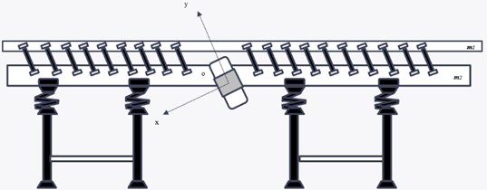
Fig. 2Schematic diagram of eccentric block rotation in the exciter (motor)
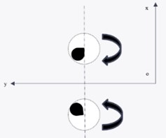
In Fig. 1, two motors of the same specification do synchronous reverse motion on the lower insulator. The structure of the eccentric block inside the motor is shown in Fig. 2. To ensure the normal operation of the vibrating screen machine, the eccentricity and mass of the eccentric block in the motor are equal, respectively. The coordinate system shown in the figure is established, and the - axis is the axis of symmetry passing through the mass center of the vibrating screen. According to the force analysis, the instantaneous centrifugal inertia force generated by the rotation of the eccentric block is always in the opposite direction along the - direction, offsetting each other. In the direction of the - axis, the forces are superposed with each other, forming a single direction excitation force.
Under the motion of the eccentric block of the motor, the magnitude of the exciting force changes periodically, which realizes the reciprocating linear motion of the vibrating screen. When the vibrating screen operates at any time , the calculation formula of its exciting force value is as follows:
where: – exciting force in the direction; – maximum exciting force; – the sum of eccentric Block Mass on Vibrator; – rotation radius of eccentric block; – rotation angular velocity of exciter.
The amplitude and frequency of the motor’s exciting force are the vibration sources that make the double-layer or even three-layer vibrating screen produce forced vibration. According to the transmission speed and screening quality requirements of the tobacco leaf, the motor speed can be adjusted and the horizontal movement speed of the vibrating screen can be controlled. Can stimulate the vibration of the vibrating machine with a larger amplitude according to the design requirements.
2.2. Analysis of motion characteristics
2.2.1. Global analysis based on momentum conservation
Eq. (1) gives the calculation formula of an exciting force. When discussing momentum, we first study the impulse. The impulse is a vector, describing the accumulation effect of force on time. The expression is:
In the case studied in this paper, the exciting force is a function of time and periodic variation, so in this case, the impulse should be expressed as:
After calculation, it is easy to obtain that the integral shown in Eq. (3) is 0. It can be seen that the impulse of exciting force in a period is 0. The impulse is 0, which means that the momentum of the system does not change in a period, that is, momentum conservation.
The expression of momentum is:
where: – total vibration mass of vibrating body and material; – moving speed of vibrating body and material.
In a period, the product of and should change periodically when is unchanged, which means that the larger the total mass of the vibrating body and the material, the smaller the corresponding velocity value.
2.2.2. Analysis of the influence law of the rigidity and quality of the double-layer screen body
If the system is composed of particles, let the mass of the th particle , the radius , the active force acting on the particle, the restraining reaction , and the inertial force , which can be obtained by using the principle of virtual work:
Then the general equation of dynamics under ideal constraint is: Among them, the virtual work of the active force is: , where: –generalized force, – generalized hypocrisy.
The virtual work of inertia force is:
where: – kinetic energy of the system. By substituting the virtual work of active force and inertia force into Eq. (5), the Lagrange equation of non-conservative system can be obtained as follows:
The motion of the vibrating screen can be regarded as a steady forced vibration composed of mass elastic-element-damping, in which mass refers to the weight of the vibrating screen equipment, elastic element refers to the damping spring device between the vibrating screen and the main building of the equipment, and damping includes spring damping and air damping. According to the theory of mechanical vibration, this kind of dynamic system can be regarded as forced vibration in an independent coordinate system.
The establishment of the differential equation of motion of the dual-mass high-frequency vibrating screen.
Fig. 3The simplified model of the dual-mass high-frequency vibrating screen
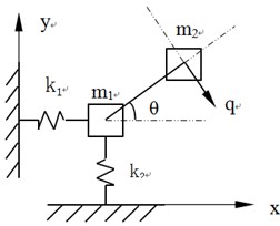
In this paper, the above-mentioned dual-mass high-frequency vibrating screen is regarded as a vibration system with three degrees of freedom, and its model is established as shown in Fig. 3:
Take into to get:
where: – the mass of the eccentric block of the motor; – rotation radius of the eccentric block; – excitation frequency; – angle between motor and horizontal plane:
By substituting and into Eq. (7), the differential equations of motion of the dual-mass high-frequency vibrating screen can be obtained:
The specific characteristic equation can be obtained as follows:
Among them, 320000 N/m, 1480000 N/m, 55°, 870 kg, 300.
According to the test results, the rigidity of the spring pieces can be obtained 34000×38 = 1292000 N/m.
By substituting the data, the stiffness matrix and mass matrix can be obtained as:
Matlab is used to solve the problem, and the first to third order natural frequencies are obtained as shown in Table 1.
Table 1Natural frequency of the dual-mass high-frequency vibrating screen
17.1214 | 38.9880 | 75.7656 |
The excitation frequency of the vibrating screen is 78.54 rad/s. From Table 1, it can be seen that the third-order natural frequency of the vibrating screen is lower than the excitation frequency, so the resonance of the high-frequency vibrating screen will not occur under the normal working frequency. However, in the process of starting and braking, the motor will pass through the resonance area of the vibrating screen, which makes the screen body shake greatly in the process of starting and braking. Therefore, we must carry out transient analysis of the screen body starting the process and study the stress changes of each part of the screen body in the starting process.
2.2.3. Change curve of natural frequency of vibrating screen with various physical parameters
As shown in Fig. 4, it is a regular curve of the natural frequency of each order of the high-frequency vibrating screen changing with the stiffness , that is, a regular curve of the natural frequency of each order with the number of upper-layer spring pieces. It can be seen from the figure that when increased from 1.02×e6 N/m to 2.04×e6 N/m, the number of spring pieces increased from 30 groups to 60 groups (each group has two spring pieces), the first and second natural frequencies of the high-frequency vibrating screen change little with K3, while the third natural frequency increases from 69.8 rad/s to 97.85 rad/s with K3. When the stiffness K3 reaches 1.31×e6 N/m, the third-order natural frequency reaches 78.33 rad/s, that is, changing the number of upper spring pieces has little effect on the low-order frequency of the vibrating screen system. Therefore, the amplitude and horizontal movement speed of the upper sieve can be controlled by changing the number of spring pieces by reasonable design, and the screening efficiency can be improved according to the tobacco feeding situation. when the number of spring piece groups is equal to 40 groups, resonance will occur at this time so that the mechanical equipment can work normally.
Fig. 4Relation curve between natural frequency and rigidity K3 of vibrating screen
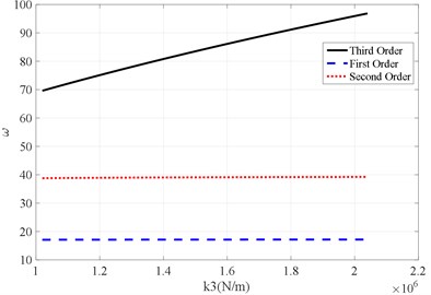
Fig. 5Relation curve between the natural frequency of vibrating screen and number of elastic supports
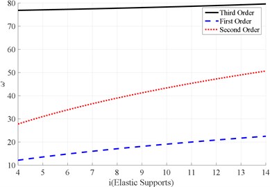
As shown in Fig. 5, when the stiffness is unchanged, the stiffness and are changed, that is, the number of elastic supports of ROSTA. It can be seen that the number of ROSTA elastic supports has little effect on the third-order natural frequency and the natural frequency increases as the number of elastic supports increases. When the number of elastic supports reaches 10, the screen body will resonate. The change of the number of lower spring pieces will affect the low-order natural frequency of the system. Considering the influence of the quality of the lower screen body, a reasonable design can effectively reduce the large lateral vibration of the vibrating screen when the machine is switched on and off.
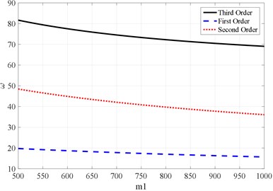
As shown in Fig. 6, when the stiffness does not change, changing the magnitude of the vibration mass m1, that is, changing the mass of the intermediate frame, the range of the third-order natural frequency changes little, but it decreases as the mass of the intermediate frame increases. When 816 kg, the screen body generates resonance. From calculation and analysis, the mass of the lower sieve body is reasonable between 600 and 1000 kg. The change of the lower sieve body mass has little effect on the vibration characteristics of the system, but if its mass is too small, it will cause a larger side directional vibration of the vibrating machine which will affect system stability.
Fig. 6Relation curve between the natural frequency of the vibrating screen and the vibration mass m1
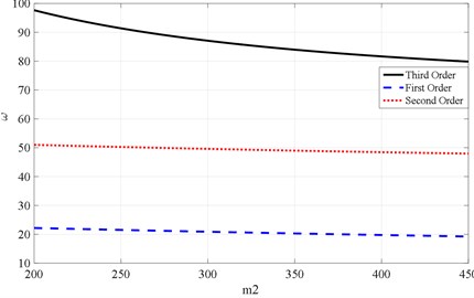
As shown in Fig. 7, when the stiffness K1, K2, K3, and the vibration mass are unchanged, changing the magnitude of the vibration mass , that is, changing the mass of the upper screen body component, has a greater impact on the third-order natural frequency. The third-order natural frequency decreases with the increases in the mass of the upper screen body. When the vibration mass of the upper screen body is about 293.4 kg, resonance will occur. By changing the size of , the occurrence of the third-order natural vibration of the system can be controlled, resulting in higher frequency and larger amplitude vibration.
Fig. 7Relation curve between the natural frequency of the vibrating screen and the vibration mass m2
3. Results and discussion
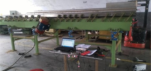
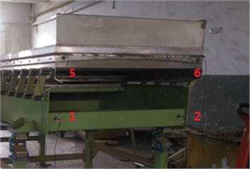
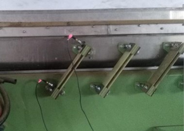
Using data acquisition and signal processing equipment (DASP), with 12 acceleration sensors and force hammers, the motion characteristics of the upper and lower screen bodies of the dual-mass vibrating screen were measured, as shown in Fig. 8. The measurement is divided into two parts. First, the amplitudes of different points on the upper and lower sieve bodies are measured to study the basic motion characteristics. Second, the motion characteristics of the upper and lower sieves are analyzed and studied through the measured images and specific amplitude data. and the effect of different numbers of spring pieces on the motion characteristics is further studied. The relationship between the horizontal and vertical vibration amplitudes of the upper and lower screen bodies and the vibration characteristic parameters of the screen shaker are studied.
Fig. 8Field diagram of double-layer vibrating screen machine test
Using force hammer sensor and 12 acceleration sensors, using the MIMO method, through the DASP modal analysis software, the rigid body modal analysis of the double-layer vibrating screen is carried out, and the elastic body modal analysis of the upper and lower screen bodies is carried out respectively.
Using a force hammer sensor and 12 acceleration sensors in Fig. 8, using the MIMO method, the DASP modal analysis software was used to perform rigid body modal analysis on the double-layer vibrating screen, and the elastic modal analysis was performed on the upper and lower sieve bodies.
3.1. Measurement of motion characteristics
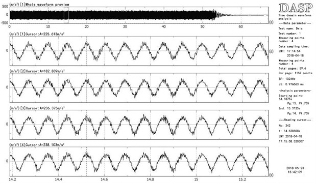
The DASP instrument was used to measure a type of high-frequency double-mass vibrating screen in the laboratory. Select two points on the lower sieve body, named point 1 and point 2; select two points on the upper sieve body, named point 5 and point 6. The arrangement of measuring points is shown in Fig. 9. The time-domain waveform analysis diagram of these four points measured by the DASP instrument is shown in Fig. 9. Where Fig. 9(a) shows the motion waveform of four points in the horizontal direction and Fig. 9(b) represents the motion waveform of four points in the vertical direction.
Fig. 9Horizontal and vertical measuring point layout of double-layer vibrating screen
a) Sensor level measuring point
b) Sensor vertical measuring point
From the waveform diagram, it can be concluded that the amplitude of the points above the lower sieve body of the dual-mass high-frequency vibrating screen is much smaller than the point amplitude of the upper sieve body in the horizontal and vertical directions.
According to the actual situation, the mass of the upper sieve of the dual-mass high-frequency vibrating screen we measured is 200 Kg; the mass of the lower sieve is 976 Kg (including the motor), and the motor that provides the exciting force for the entire vibrating screen is located in the lower sieve, which makes the mass of the lower sieve larger than the mass of the upper sieve. According to the momentum conservation and the derived Eq. (4) obtained in the first part, it is found that the momentum conservation relationship is satisfied when the measured waveform amplitude and the vibration quality of the upper and lower tanks are brought into the momentum conservation Eq. (4) for calculation, which verifies the correctness of the theoretical research in the first part.
Fig. 10Time-domain waveform comparison of sieve measurement points above and below
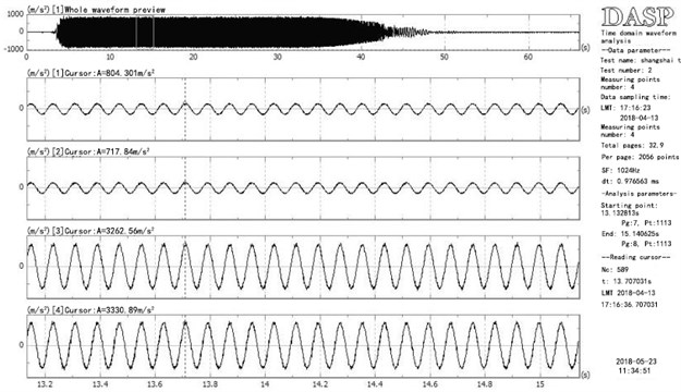
a) Horizontal amplitude of measuring points
b) Vertical amplitude of measuring points
The waveform diagram of Fig. 10 is sorted out and summarized to obtain a correspondence table between test points and amplitudes, as shown in Table 2.
According to the table of horizontal and vertical amplitudes of the working state, it can be concluded that the amplitudes of the points on the upper and lower sieve bodies have different positive and negative amplitudes at the same time, which means that the motion is reversed, which probably meets the law of conservation of momentum.
The four corners of the lower sieve body are selected as test points, and the displacement waveform in the horizontal direction is measured, as shown in Fig. 11.
Table 2Amplitude of upper and lower entity test points
Horizontal amplitude of measuring points | Vertical amplitude of measuring point | ||
Measuring points | Amplitude A | Measuring points | Amplitude A |
1 | 8.04 | 1 | –8.62 |
2 | 7.17 | 2 | –8.77 |
5 | –32.62 | 5 | 33.48 |
6 | –33.30 | 6 | 35.24 |
Fig. 11Time-domain waveform diagram of the corner points of the lower sieve
From Fig. 11, we can see that the motion of the sieve body is periodic, and the vibration amplitudes of the four corner points are relatively similar, and the vibration periods are consistent, indicating that the relative vibration of the upper and lower grooves can be simplified into their respective rigid body vibration.
3.2. Effect of spring plate number on motion characteristics
The different number of spring leaves influences the motion characteristics of the screen body of the vibrating screen. Therefore, it is an important research direction of this paper to make the motion of the screen body controllable by changing the number of spring leaves.
To ensure the safe and stable operation of the vibrating screen, we change the number of spring leaf groups used by the vibrating screen and use the DASP to measure the motion waveform of the vibrating screen under different spring leaf groups to obtain the required research data.
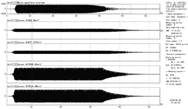
To ensure the normal and safe operation of the vibrating screen, we have set 20 sets of spring pieces, 19 sets of spring pieces, and 18 sets of spring pieces, and measured the movement of the points on the upper and sieve bodies in three cases, and obtained the corresponding relationship. The four test points above the lower sieve body are named point 1, point 2, point 3, and point 4; the four points above the upper sieve body are point 5, point 6, point 7, and point 8. The movement of these 8 points in horizontal and vertical directions was measured by the DASP instrument. Take the motion waveform diagram of each point under the normal operation of 20 groups of springs as an example, as shown in Fig. 12.
Fig. 12(a) shows the movement of four measuring points on the lower sieve body under normal operation of 20 sets of spring pieces, and Fig. 12(b) shows the movement of four measuring points on the upper sieve body. After the motion stabilized, the amplitude of the 8 points in the horizontal direction was tested. In the same way, the horizontal motion of 8 points in the two cases of 19 sets of spring pieces and 18 sets of spring pieces is obtained, and the 1, 2, 3, and 4 points are located in the lower trough; the 5, 6, 7, and 8 points are located upper trough. Table 3 lists the comparison of eight points of motion of the vibrating screen in normal operation under three different numbers of spring sheets, which are expressed by amplitude.
Fig. 12Comparison of vibration of testing points of the vibrating screen machine with different number of spring pieces
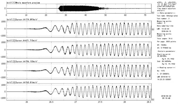
a)
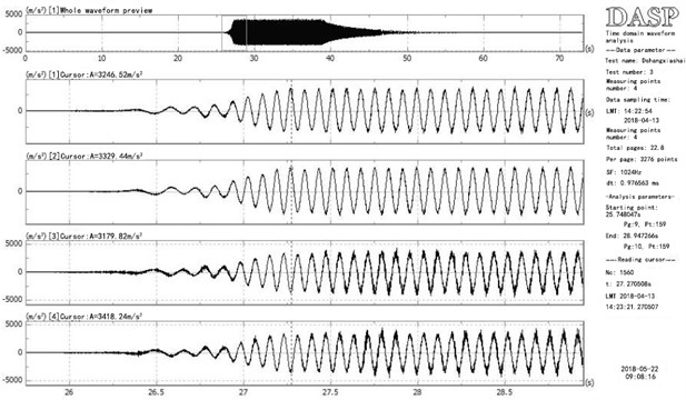
b)
Table 3Comparison of amplitude values under different numbers of spring pieces
Numbers of spring pieces | 1 | 2 | 3 | 4 | 5 | 6 | 7 | 8 |
20 | 7.85 | 6.64 | 8.49 | 7.25 | 32.46 | 33.29 | 31.79 | 34.18 |
19 | 7.09 | 8.45 | 7.90 | 8.25 | 37.17 | 35.75 | 40.25 | 36.63 |
18 | 6.23 | 7.05 | 5.25 | 7.42 | 40.68 | 35.43 | 51.07 | 36.21 |
From Table 3, it can be concluded that for the points on the lower sieve body, the number of spring sheets has little effect on the points above. Considering the unavoidable errors in the actual operation, the amplitude of 19 groups of spring sheets is larger than that of 18 groups of spring sheets; the amplitude of three groups of spring sheets will fluctuate due to the specific position of the test point. As the number of upper spring pieces decreases, its rigidity also decreases. The amplitude of the upper screen body of the 18 groups of spring pieces is higher than that of the other two groups, and the third-order natural frequency of the system decreases, which is closer to the operating frequency of the motor 12.5 Hz, so the amplitude is larger.
3.3. Rigid body modal test and parameter analysis of double-layer vibrating screen machine
Fig. 13 shows the frequency response curves of the sensors located at the upper and lower troughs. The sensors are arranged horizontally and the hammer is excited horizontally. The horizontal vibration frequencies of the upper and lower vibrating screens are shown in Table 4 below. The measured natural frequency values are consistent. The 20, 19, and 18 sets of spring sheets are tested in the same way. The natural frequencies are shown in the Table 4.
Fig. 13Comparison of vibration at test points of the vibrating screen with different numbers of spring blades
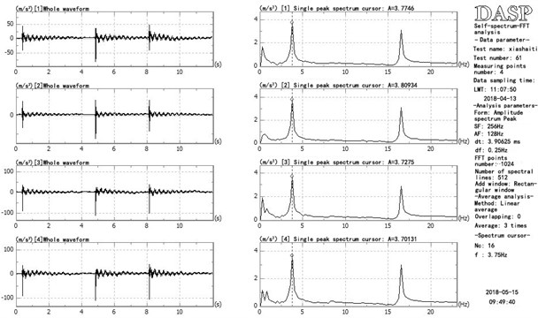
a) Lower trough
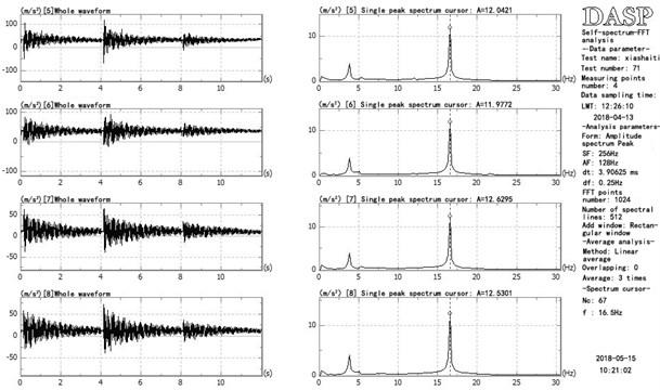
b) Upper trough
Table 4Slot horizontal frequency table with different sensor positions
Numbers of spring pieces | Sensor positions | Upper trough | Lower trough |
20 | 下 | 16.5 | 3.75 |
20 | 上 | 16.5 | 3.75 |
19 | 下 | 16.1 | 3.55 |
18 | 下 | 15.5 | 3.5 |
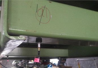
The vibration amplitude along the vertical direction of the spring plate corresponding to the position of the connecting upper and lower grooves is studied. As shown in Fig. 14, the position of the upper groove is 38.39 m/s2, and the acceleration of the position of the lower groove is 6.96 m/s2, which is a 5.5:1 relationship. The mass ratio of the upper and lower grooves is about 1:5, so the vertical direction along the spring plate also basically meets the law of momentum conservation.
For the lower sieve body, it can be seen from the measured data that the change of the number of spring plate groups has a greater impact on the motion amplitude of the upper sieve body, and with the increase of the number of spring plate groups, the amplitude of the measuring points on the upper sieve body as a whole has a decreasing trend. With the increase in the number of spring plates and the increase of the overall stiffness, the vibration amplitude will decrease. Increasing or decreasing the number of spring plate has a slight effect on the vibration frequency of the upper and lower tanks.
Fig. 14Comparison of vibration of test points at the upper and lower grooves in the direction of the vertical spring leaf
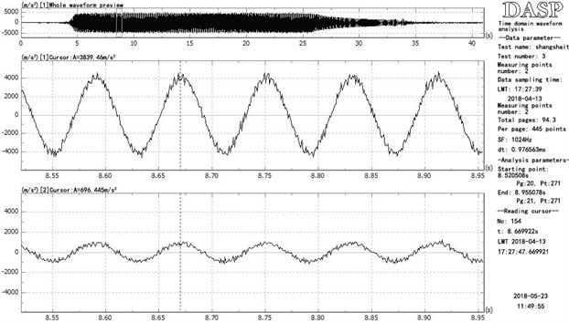
a) Amplitude graph
b) Measuring point position
3.4. Vibrating screen modal test
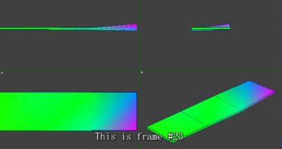
12 piezoelectric acceleration sensors and a force hammer were used to attain the rigid body modal of the double-layer vibrating screen by the MIMO hammering method, as shown in Fig. 15.
The frequency of the motor in normal operation is 12.5 Hz. The modal testing frequency of the elastomer in the lower groove of the motor is shown in Table 5.
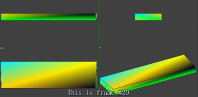
Because the upper groove body will produce a strong wind whistle when the machine is running, it is necessary to carry out an in-plane modal analysis. The results show that the local relative stiffness of the design is small, warping, and twisting vibration modes will occur. The modal analysis is shown in Fig. 16, The overall stiffness of the upper groove body needs to be increased or strengthened locally. The practice has proven that the follow-up has played an optimization and improvement effect on the design of the vibrating screen in Hangzhou Tobacco Factory. In addition to the relative reverse motion during operation, the upper and lower grooves are shown in Fig. 17(a), and there is relative torsional vibration outside the plane, as shown in Fig. 17(b), but the amplitude is small, and its influence should be considered in the structural design and selection of the spring sheets.
Table 5Modal frequency and damping
Order | Frequency (Hz) | Damping (%) |
1 | 3.697 | 2.041 |
2 | 16.505 | 0.351 |
3 | 35.286 | 1.047 |
4 | 51.920 | 2.203 |
Fig. 15Modal test of the vibrating screen
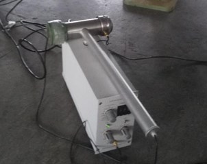
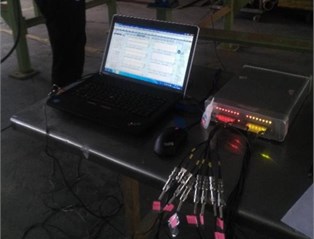
Fig. 16Modal of upper groove of the vibrating screen
a) Distortion
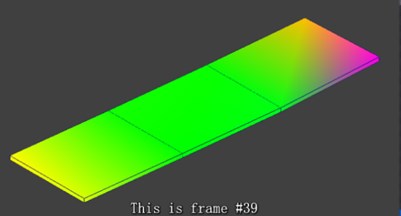
b) Warpage
Fig. 17Rigid body mode of the upper and lower trough of vibrating screen
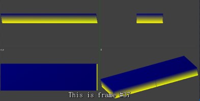
a) Horizontal rubbing
b) Relative torsion
The picture below shows a vibrating screen machine placed on the second floor of an industrial plant in Hangzhou. It is required to minimize the vibration of the floor when the machine is working. Therefore, we control the mass ratio of and , reasonable choosing elastic support K1 and adjusting the number of spring pieces to control K2 according to the law of influence of the above parameters on the vibrating screen system to make the machine can operate normally at 12.33 Hz while greatly reducing the vibration to the floor.
Fig. 18Test site pictures
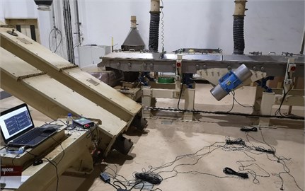
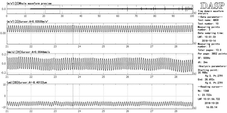
Fig. 19The vertical displacement and velocity curve of the upper tank (normal work maximum displacement 360 um, maximum speed 26.8 mm/s; switch machine maximum displacement 754 um, maximum speed 30.2 mm/s)
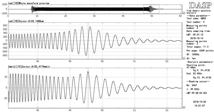
Fig. 20The vertical displacement and speed curve of the lower support (normal working maximum displacement 2 um, maximum speed 0.162 mm/s; switch machine maximum displacement 2.35 um, maximum speed 0.12 mm/s gradually decrease)
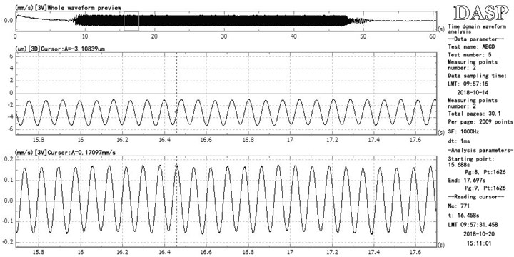
When the double-layer vibrating screen is working normally, by comparing the maximum displacement and velocity amplitude between the upper and lower screen bodies of the vibrating screen and the floor, it can be found that the design requirements are well met.
Fig. 21The machine is running normally, the acceleration, velocity, and displacement curve of the ground position (normal work, the maximum acceleration is 0.0119 mm/s, the maximum speed is 0.162 mm/s, the maximum displacement is 2.2 um)
4. Conclusions
Based on the above research on the motion characteristics of the sieve body and the study of the motion characteristics of the vibrating screen, we get some conclusions about the controllability of the vibrating screen.
The power source of the double-layer high-frequency vibrating screen machine is the key part of the controllable vibration, and the power comes from the motor installed on the lower screen body. The eccentric rotor of the two motors rotates reversely so that the vibrating screen obtains an exciting force to vibrate. The mass of the eccentric rotor in the motor, the angular velocity of rotation, and the radius of gyration of the rotor are three key quantities that affect the vibration characteristics of the vibrating screen. By increasing the mass of the eccentric rotor in the motor, the angular velocity of rotation and the radius of gyration, the vibration amplitude of the screen body of the vibrating screen can be increased.
The parameters of the double-layer high-frequency vibrating screen itself are also the influencing factors of controllability. The stiffness of the spring piece selected for the vibrating screen directly affects the vibration amplitude of the screen body. From the test data shown in Table 3, it is can be known that the greater the stiffness of the spring piece used, the smaller the vibration amplitude of the screen body. However, the increase or decrease of the number of spring piece has a limited influence on the vibration amplitude, which will affect the vibration frequency domain parameters of the upper and lower troughs. The selection of the number of spring pieces should also consider the overall vibrating quality.
The quality of the material placed in the vibrating screen is also a factor that affects the screen of the vibrating screen. According to the actual screening requirements, the appropriate quality of materials should be placed so that the screening requirements can be met. The relative vibration amplitude of the upper and lower tanks is mainly determined by the relative mass ratio and the number and stiffness of the spring pieces.
Through the experimental measurement, the overall motion of the vibrating screen machine in the project roughly meets the principle of conservation of momentum. We verified the correctness of the derivation results in the first part.
Through research, we have obtained the controllable design of the upper and lower sieve bodies of the double-layer high-frequency vibrating screen machine, which should be considered from the three aspects: the motor, the vibrating screen machine, and the material. The specific design should refer to the following conclusions:
1) The rotor in the motor affects the vibration of the screen. Increasing any one of the masses of the rotor, angular velocity and the radius of gyration will expand the vibration amplitude of the screen. The relative vibration amplitude of the upper and lower troughs mainly depends on their relative mass ratio and the number and stiffness of the spring pieces.
2) The number and performance of the rigid plate used by the vibrating screen itself affect the vibration characteristics of the screen body. The more spring sheets are used, the greater the stiffness of the spring sheets, and the smaller the vibration amplitude of the screen body. The increase or decrease of the number of spring sheets has a limited influence on the vibration amplitude, which will affect the vibration frequency domain parameters of the upper and lower troughs. The selection of the number of spring sheets should still consider the overall vibrating quality.
3) The material and the falling height of the material placed in the vibrating screen will affect the vibration of the screen body, and it should be controlled according to the specific screening requirements. The subsequent effects can be accurately tested and simulated.
4) The experimental results show that the overall motion of the vibrating screen in engineering, including horizontal, vertical, and vertical directions along with the spring pieces, approximately meets the law of momentum conservation, and can be used as an important reference factor for design.
References
-
Zhou Bi Optimization Design and Experimental Research over a New Composite Vibrating Screen. Huaqiao University, 2016.
-
Pu Wenzhuo Dynamic Analysis and Application of Double Vibrating Motor Linear Multilayer Vibrating Screen. Jiangsu University, 2017.
-
Wang Guifeng Screening efficiency and screen length of a linear vibrating screen using DEM 3D simulation. Mining Science and Technology, Vol. 21, Issue 3, 2011, p. 451-455.
-
Li Zhanfu, Tong Xin, Zhou Bi, Wang Xiaoyue Modeling and parameter optimization for the design of vibrating screens. Minerals Engineering, Vol. 83, 2015, p. 149-155.
-
Shen Guolang Tong Xin Li Zhanfu Study on the number of simulation experiments of vibrating screen based on DEM. Machine Design and Research, Vol. 35, Issue 2, 2019, p. 110-112.
-
He Bin, Zhao Chun Yu, Han Yan Long, Wen Bang Chun Design method of dynamic parameters for a dual-mass vibrating system. Journal of Northeastern University (Natural Science), Vol. 37, Issue 1, 2016, p. 127-132.
-
Peng Z.-K., Lang Z.-Q., Meng G., Billings S. A. Reducing force transmissibility in multiple degrees of freedom structures through anti-symmetric nonlinear viscous damping. Acta Mechanica Sinica (English Series), Vol. 5, 2012, p. 1436-1448.
-
Zhao Huanshuai Numerical Simulation and analysis on main technical parameters of high frequency vibration screen. Coal Science and Technology, Vol. 10, 2012, p. 88-91.
-
Wang Feng Development and prospect of screening machinery. Mining and Processing Equipment, Vol. 1, 2004, p. 37-39.
-
Guo Nianqin, Kuang Yongjiang Research and development of vibrating screen home and abroad. World Nonferrous Metals, Vol. 5, 2009, p. 26-27.
-
Delaney Gary W., Cleary Paul W., Hilden Marko, Morrison Rob D. Testing the validity of the spherical DEM model in simulating real granular screening processes. Chemical Engineering Science, Vol. 68, Issue 1, 2012, p. 215-226.
-
Cleary Paul W. Prediction of coupled particle and fluid flows using DEM and SPH. Minerals Engineering, Vol. 73, 2015, p. 85-99.
-
Ramatsetse B., Mpofu K., Makinde O. Failure and sensitivity analysis of a reconfigurable vibrating screen using finite element analysis. Case Studies in Engineering Failure Analysis, Vol. 9, 2017, p. 40-51.
-
Makinde O. A., Ramatsetse B. I., Mpofu K. Review of vibrating screen development trends: linking the past and the future in mining machinery industries. International Journal of Mineral Processing, Vol. 145, 2015, p. 17-22.
-
Moncada M., Manuel, Rodriguez, Cristian G. Dynamic modeling of a vibrating screen considering the ore inertia and force of the ore over the screen calculated with discrete element method. Shock and Vibration, Vol. 2018, 2018, p. 1714738.
-
Baragetti S., Villa F. A dynamic optimization theoretical method for heavy loaded vibrating screens. Nonlinear Dynamics, Vol. 78, Issue 1, 2014, p. 609-627.
-
Jiang H., Zhao Y., Duan C., et al. Dynamic characteristics of an equal-thickness screen with a variable amplitude and screening analysis. Powder Technology, Vol. 311, 2017, p. 239-246.
-
Liu Wen-Xin Analysis and commentary on foreign vibrating screen technology. Goal Preparation Technology, Vol. 2, 2015, p. 88-91.
-
Chu Sheng Liu, Shi Min Zhang, Hai Pei Zhou, Jun Li, Yun Fei Xia, Li Ping Peng, Hong Wang Dynamic analysis and simulation of four-axis forced synchronizing banana vibrating screen of variable linear trajectory. Journal of Central South University of Technology, Vol. 19, 2012, p. 1530-1536.
-
Mohammad Rezaiee Pajand, Seyed Mojtaba Hozhabrossadati Analytical and numerical method for free vibration of double-axially functionally graded beams. Composite Structures, Vol. 152, 2016, p. 488-498.
-
Xiao Jianzhang, Tong Xin Characteristics and efficiency of a new vibrating screen with a swing trace. Particuology, Vol. 11, Issue 5, 2013, p. 601-606.
About this article

This work was supported by Yanshan University Young Teachers Independent Research Fund (No. 15LGA011).
