Abstract
Nowadays, piezoelectric linear actuators draw wide attention of researchers around world as its advantages of simple structure, high precision and rapid response. To improve the performance of the non-resonant piezoelectric motor, a symmetric piezoelectric linear motor driven by double-foot is studied in the paper. The vibration model of the stator is established based on the structure and the working mechanism of motor. Then guide mechanism and preload device is designed and a prototype is fabricated to verify the feasibility of structure. The performances of motor under different driving signal are tested in experiment. By applying three-phase square-triangular waves signal and four-phase sine waves signal of peak to peak value 100 V with 50 V offset and frequency of 100 Hz, the speed of prototype reaches 733 μm/s and 667 μm/s and the maximum thrust is 8.34 N and 6.31 N respectively.
1. Introduction
Piezoelectric linear motors are widely used in the various application fields as its advantages of simple structure, high precision and rapid response [1-8]. The existing piezoelectric linear motors can be classified into resonant type and non-resonant type. In the resonant type, piezoelectric ceramic is used as the driving element [9-11]. In order to generate linear motion, vibration at ultrasonic frequency range on an oscillating element is transferred to a moving element through frictional coupling [12-15]. Usually, these motors are greatly affected by the change of temperature and structure parameter. Since the resonant state is unstable, it is difficult to control the motor. Piezoelectric stack [16], which would output large displacement and thrust under small driving voltage, is used in non-resonant motors. Thus the non-resonant motor will work stably even not in resonant state [17].
In recent decades, by means of piezoelectric stack, all kinds of stepping motors with high positioning accuracy are developed [18, 19]. Among which the inchworm principle type [20, 21] and inertial impact type [22, 23] linear motors are well known. However, high requirements are put forward in drive signal and positioning accuracy. Inchworm motor utilizes alternating motion of clamping mechanism and driving mechanism to make the mover do linear motion continuously. It has high positioning accuracy and strong carrying capacity, but its structure is complex and its performance is obviously affected by the processing precision and assembly situation. Inertial piezoelectric linear motor utilizes the rapid deformation of piezoelectric element to produce large inertial impact in the moving element. Thus it will be driving the mechanism with the advantages of high thrust and large stroke. But it requires driving and control signal of high quality. In recent years, professor Huang from Nanjing University of Aeronautics and Astronautics proposed several kinds of non-resonant motors based on inverse piezoelectric effect [24, 25]. To improve the performance of these motors, a symmetric piezoelectric linear motor driving by double-foot of stator is proposed in the paper.
2. Modeling and analysis
To summarize the advantages and disadvantages of stators in traditional motors, a novel symmetric stator which has the merits of simple structure, convenient assembly and high thrust is designed in the paper. Fig. 1 gives the structure of stator, which includes the left stator 1 and the right stator 2.
Fig. 1Structure of stator
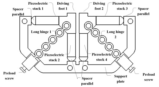
There are two operative modes for this stator. Following are the motion analysis of the stator working under two operative modes. One is the Elliptical motion mode
The following equation shows the input voltages (sine waves with 90° phase difference) applied on the four piezoelectric stack 1 to stack 4 under first mode:
Longitudinal vibration model of the stator is shown in Fig. 2.
Fig. 2Longitudinal vibration model of the stator
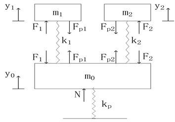
Where , is the mass of the driving foot in left and right stator and , and is the mass of the rest part of stator. , is the stiffness of longitudinal piezoelectric stack and spring hinge of the driving foot in left and right stator respectively. is the stiffness of the preloading device. and are the preload force of the longitudinal piezoelectric stack while and are the output force of two longitudinal piezoelectric stacks. is the precompression. and is the longitudinal displacement of the driving foot in left and right stator when , and is the longitudinal displacement of the rest part of the stator. Contact stiffness is defined as when the stator contact with the mover. and is the contact force of the driving foot in left and right stator.
Then the longitudinal vibration equation of the stator is derived as following:
where, and is the output force of the longitudinal piezoelectric stack, which can be written as:
where, is the stiffness of the piezoelectric stack and is the total stiffness of the rest part of the stator. According to the experiments of previous motor, it is found that the precompression almost does not change when the stator is under working mode. So the precompression can be expressed by:
Thus, it can be solved as:
Lateral vibration model is built similar to longitudinal vibration model without press compression. The lateral vibration displacement equation of the stator is written as:
The equation of the moving trajectory of the stator driving foot can be written as:
where:
From the equation, it is obviously that the moving trajectory is a elliptical. Two driving feet drive the mover alternatively to do linear motion when every driving foot has driver stage and return stage. Fig. 3 shows the force diagram of two stators and the mover when the stator 1 is under driver stage and the stator 2 is under return stage. The friction is under consideration.
Fig. 3Force diagram of two stators and the mover
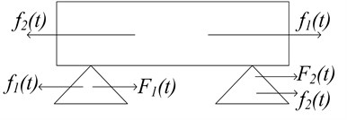
Here, and is the friction between two stators and the mover when and is the output force of lateral piezoelectric stacks. Then the following equation is derived:
and
where, and is coefficient of friction between two stators and the mover. When the mass of the mover is , the acceleration equation of the mover is written as:
Also, the velocity of the mover can be expressed by:
If there is a force loaded on the mover, the velocity equation of the mover in this half circle is:
In the other half circle, the stator 1 and the stator 2 exchange the motion and the mover keep the velocity to do the linear motion. By repeating this two stages, the stator will achieve a constant liner motion when applying sine waves on the piezoelectric stacks. From the above deduction, the velocity of the mover has the relationship with the structure parameters, the coefficient of friction and the load on the mover.
The other operative mode is rectangular motion mode. Fig. 4 shows the input voltages (square wave and triangle wave) applied on the four piezoelectric stack 1 to stack 4 under second mode.
Fig. 4The input signals in second mode
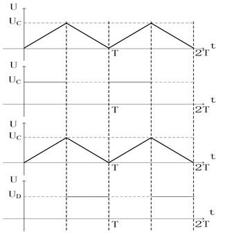
The voltage equation can be written as:
where, is the remainder operator. So that the longitudinal vibration equation can be derived as:
when the stator 1 is under driver stage and the stator 2 is under return stage, the lateral vibration equation is written as:
then the lateral displacement can be expressed by:
Also, the velocity of mover is:
The mover does uniform linear motion with square wave and triangle wave, which would be more stable than using sine wave signals.
To investigate the transient dynamics of the structure, FEM analysis were carried out using the finite element software ANSYS. Fig. 5 shows the model and load of the motors. With a driving signal of 100 V and 100 Hz applied on the piezoelectric stack, dynamic simulation results of two operative modes is obtained.
Fig. 5The dynamic simulation
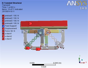
Fig. 6(a) shows motion trail of the top of the driving foot when sine waves is applied. Also Fig. 6(b) shows displacement of the mover at the same time. It is obviously that driving foot of stator do elliptical motion to push the mover do linear motion. However, Fig. 6(b) shows the mover can only do linear motion stably in a half period. It means the stator cannot push the mover effectively, which degrade performance of the motor.
Fig. 6The motion trail of a) driving foot and b) mover in first operation mode
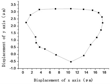
a)
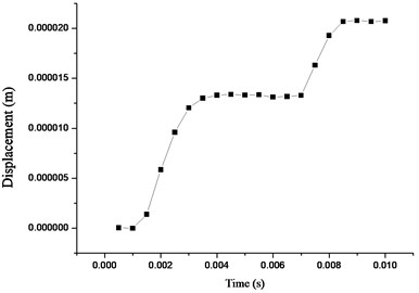
b)
Fig. 7(a) shows motion trail of the top of the driving foot in the rectangular motion operative mode. Also Fig. 7(b) shows displacement of the mover at the same time. It can be obtained the mover do uniform linear motion in this mode. Through the simulation results, when the second mode (square wave and triangle wave signal) is operated, the motion of motor would be more stable than the first mode (sine waves signal) is operated.
To analysis some key point in one circle of stator, the motion mechanism can be showed as Fig. 8.
Fig. 7The motion trail of a) driving foot and b) mover in second operation mode
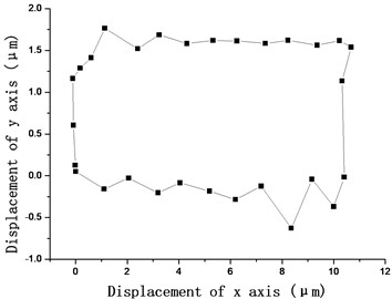
a)
b)
Fig. 8Motion mechanism
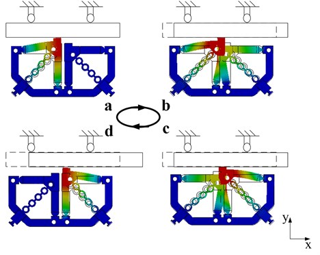
There are four working phases of the motor in the Fig. 8, where, a and c represents for the next moment of the 0 and while b and d represents for the previous moment of the and .
(1) In the first phase a, the piezoelectric stack 2 extends in y direction with a voltage applied on it. At this moment, the left stator driving foot pushes the mover.
(2) In the second phase b, the piezoelectric stack 1 and 3 extends a micro length in direction and negative direction. From phase a to phase b, the left stator driving foot drives the mover to move displacement in direction.
(3) In the third phase c, the piezoelectric stack 2 return to the original length. At the same time, the piezoelectric stack 4 extends in y direction with a voltage applied on it. Thus the right stator driving foot pushes the mover.
(4) In the fourth phase d, the piezoelectric stack 1 and 3 extends a micro length in negative direction and direction. From phase c to phase d, the right stator driving foot drives the mover to move displacement in direction.
In a circle, the stator pushes the mover to move displacement 2 in direction. By repeating steps (1) to (4), the motor will achieve a large stroke linear motion.
3. Experiment
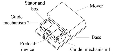
To achieve the above principle, the whole structure of the motor is designed as shown in Fig. 9.
Fig. 9The whole structure of the motor
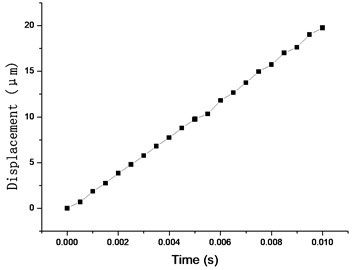
In performance test, four piezoelectric stacks NAC2013-H14 produced by Noliac company is used in the structure. The driving signal is applied by the signal generator and the power amplifier. This signal is displayed on the oscilloscope and is also applied on the stacks of the motor, which makes the motor in operative mode. The displacement of the motor can be measured by the laser sensor LK-H020 from Keyence Company with the resolution of 1nm.
When sine signal and square-triangle wave signal is applied on the four stacks, the velocity of the motor versus driving frequency is as shown in Fig. 10.
In Fig. 10, it is seen there is a linear relationship between frequency of the signal and velocity of the motor. By applying three-phase square-triangular waves voltage signal and four-phase sine waves voltage signal of peak to peak value 100 V with 50 V offset and frequency of 100 Hz, the velocity of prototype reaches 733 μm/s and 667 μm/s
As a load experiment is done by using the motor to pull the weights, the results is shown in Fig. 11.
Fig. 10Velocity of the motor versus driving frequency
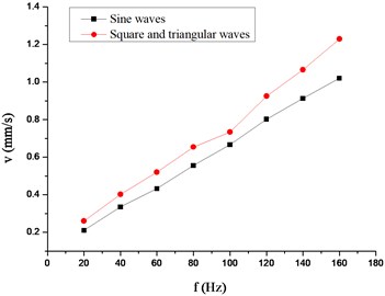
Fig. 11Load characteristic of the motor
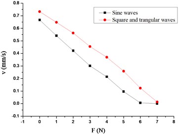
From the load experiment results in Fig. 8, it is concluded when three-phase square-triangular waves voltage signal and four-phase sine waves voltage signal of peak to peak value 100 V with 50 V offset and frequency of 100 Hz is applied on the stacks, the maximum output force is 8.34 N and 6.31 N respectively.
4. Conclusions
A novel symmetric stator which has the merits of simple structure, convenient assembly and high thrust is designed in the paper. As piezoelectric stack is used as the driving element, the performance of motor can be hardly affected by the temperature and structure parameter. Modeling and analysis of stator in the motor are done under two different operative modes. The power requirements of two modes is simple. Also, the motion mechanism is discussed in the paper. Finally, the whole structure of the motor is designed and the experiment results validate the principle of this linear motor. In the experiment, by applying three-phase square-triangular waves signal and four-phase sine waves signal of peak to peak value 100 V with 50 V offset and frequency of 100 Hz, the speed of prototype reaches 733 μm/s and 667 μm/s and the maximum output force is 8.34 N and 6.31 N respectively. It is obviously that the speed capacity and the load capacity of the motor when three-phase square-triangular waves signal is applied are superior to it when four-phase sine waves signal is applied. More research will be focused on the motion repeatability, performance improvement and so on.
References
-
Yoon M., Khansur N. H., Lee K., Park Y. M. Compact size ultrasonic linear motor using a dome shaped piezoelectric actuator. Journal of Electroceramics, Vol. 28, Issues 2-3, 2012, p. 123-131.
-
Shi Y. L., Li Y. B., Zhao C. S. Optimum design of a linear ultrasonic motor based on in-plane modes. Proceedings of the CSEE, Vol. 28, Issue 30, 2008, p. 56-60.
-
Li J., Sedaghati R., Dargahi J., Waechter D. Design and development of a new piezoelectric linear inchworm (R) actuator. Mechatronics, Vol. 15, Issue 6, 2005, p. 651-681.
-
Chen Q. F., Yao D. J., Kim C. J., Carman G. P. Mesoscale actuator device: micro interlocking mechanism to transfer macro load. Sensors and Actuators A-Physical, Vol. 73, Issues 1-2, 1999, p. 30-36.
-
Renner C., Niedermann P., Kent A. D., Fischer O. A vertical piezoelectric inertial slider. Review of Scientific Instruments, Vol. 61, Issue 3, 1990, p. 965-967.
-
Uchino K. Piezoelectric ultrasonic motors: overview. Smart Materials and Structures, Vol. 7, Issue 3, 1998, p. 273-285.
-
Tounsi N., Mestiri R., Keirsbulck L., Ouallin H., Hanchi S., Aloui F. Experimental study of flow control on bluff body using piezoelectric actuators. Journal of Applied Fluid Mechanics, Vol. 9, Issue 22, 2016, p. 827-838.
-
Bekiroglu E. Ultrasonic motors: Their models, drives, controls and applications. Journal of Electroceramics, Vol. 20, Issues 3-4, 2008, p. 277-286.
-
Wallaschek J. Contact mechanics of piezoelectric ultrasonic motors. Smart Materials and Structures, Vol. 7, Issue 3, 1998, p. 369-381.
-
Lu F., Lee H. P., Lim S. P. Contact modeling of viscoelastic friction layer of traveling wave ultrasonic motors. Smart Materials and Structures, Vol. 10, Issue 2, 2001, p. 314-320.
-
Le Moal P., Cusin P. Optimization of travelling wave ultrasonic motors using a three-dimensional analysis of the contact mechanism at the stator-rotor interface. European Journal of Mechanics A-Solids, Vol. 18, Issue 6, 1999, p. 1061-1084.
-
Liu Y., Chen W., Xu D., Feng P., Liu J. Improvement of a rectangle-shape linear piezoelectric motor with four driving feet. Ceramics International, Vol. 4, Issue 11, 2015, p. 594-601.
-
Asumi K., Fukunaga R., Fujimura T., Kurosawa M. K. Miniaturization of a V-shape transducer ultrasonic motor. Japanese Journal of Applied Physics, Vol. 48, 2009.
-
Flynn A. M. Performance of ultrasonic mini-motors using design of experiments. Smart Materials and Structures, Vol. 7, Issue 3, 1998, p. 286-294.
-
Zhou S., Zhao C., Huang W. Contact analysis of traveling wave type rotary ultrasonic motor in space domain. Proceedings of the CSEE, Vol. 30, Issue 12, 2010, p. 63-68.
-
Takahashi S. Multilayer piezoelectric ceramic actuators and their applications. Japanese Journal of Applied Physics, Supplement, Vol. 24, 1985, p. 41-45.
-
Shi Y. L., Zhao C. S. A new standing-wave-type linear ultrasonic motor based on in-plane modes. Ultrasonics, Vol. 51, Issue 4, 2011, p. 397-404.
-
Mynderse J. A., Chiu G. T. C. Modeling of a dynamic mirror with antagonistic piezoelectric stack actuation. Journal of Dynamic Systems, Measurement, and Control, Vol. 136, Issue 2, 2014, p. 24501.
-
Huang H., Zhao H., Fan Z., Zhang H., Ma Z., Yang Z. Analysis and experiments of a novel and compact 3-DOF precision positioning platform. Journal of Mechanical Science and Technology, Vol. 27, Issue 11, 2013, p. 3347-3356.
-
Shupeng W., Zhihui Z., Luquan R., Hongwei Z., Yunhong L., Bing Z. Design and driving characteristic researches of a novel bionic stepping piezoelectric actuator with large load capacity based on clamping blocks. Microsystem Technologies, Vol. 21, Issue 8, 2015, p. 1757-1765.
-
Kim J., Lee J. H. Self-moving cell linear motor using piezoelectric stack actuators. Smart Materials and Structures, Vol. 14, Issue 5, 2005, p. 934-940.
-
Hunstig M., Hemsel T., Sextro W. Stick-slip and slip-slip operation of piezoelectric inertia drives – Part II: frequency-limited excitation. Sensors and Actuators A-Physical, Vol. 200, 2013, p. 79-89.
-
Hunstig M., Hemsel T., Sextro W. Stick-slip and slip-slip operation of piezoelectric inertia drives. Part I: ideal excitation. Sensors and Actuators A-Physical, Vol. 200, 2013, p. 90-100.
-
Liu W. H., Wang Y., Huang W. Q., Ding Q. J. A linear stepping piezoelectric motor using inertial impact driving. Applied Mechanics and Materials, Vols. 226-228, 2012, p. 693-696.
-
Pan S., Huang W. Q., Wang Y., Zhao C. S. High efficiency driving of linear motor based on piezoelectric actuator. Optics and Precision Engineering, Vol. 19, Issue 10, 2011, p. 2464-2471.
Cited by
About this article

This work was supported in part by the National Natural Science Foundation of China (No. 51375224) and AVIC Produce-Learn-Research Projects (CXY2013NH09).
