Abstract
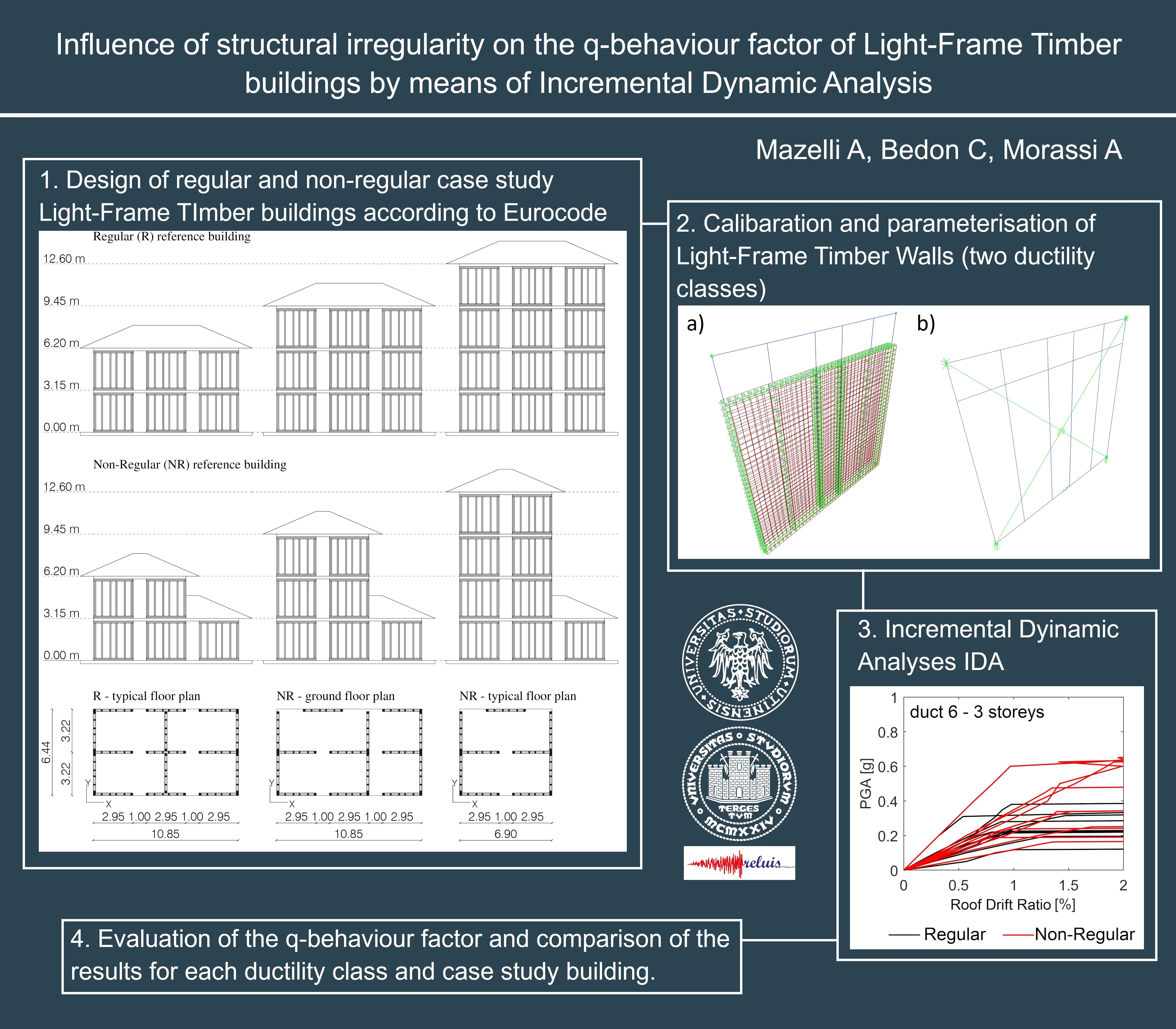
This paper investigates the role of sheathing-to-framing connection ductility in the evaluation of the structural -behaviour factor for Light-Frame Timber (LFT) buildings, by means of Incremental Dynamic Analyses (IDA). This approach allows to consider nonlinear cyclic behaviour of the walls, which cannot be taken into account with the static approaches used in most of the available literature on LFT buildings. To this aim, Finite Element wall models, preliminary calibrated towards a cyclic full-scale experimental test, are built to study six case-study buildings, both regular and non-regular, with 2, 3 or 4 storeys, which were designed according to Eurocode and Capacity Design provisions. Parametric analyses are performed by varying the displacement-ductility of the panel. Finally, numerical results are discussed in terms of -behaviour factor, and its sensitivity to structural irregularities, with respect to existing code provisions for timber buildings.
Highlights
- Evaluation of the q-behaviour factor for regular and non-regular Light-Frame Timber buildings by IDA
- LFT wall models were validated by means of a full-scale experimental test
- Parameterized analyses with 2 ductility classes for the sheathing to frame connection
1. Introduction
In last years, the growing sensibility towards environmental preservation helped the spread of wooden buildings also in those regions (like Southern Europe) where other constructional materials, such as reinforced concrete or masonry, have been traditionally used for constructions. The interest in timber buildings is related to their sustainability and environmental impact [1]. In addition, prefabrication technologies allow a reduction in construction time, which is directly connected to economic benefits.
Despite the arrival of new wood-based engineered products such as Cross Laminated Timber (CLT), Light-Frame Timber (LFT) structures still represent an excellent alternative for low-medium rise buildings, where it is possible to save material and have rather good ductile capacity, which is mostly ensured by dissipation of each sheathing-to-frame connection.
Such a dissipation capacity has a key role for LFT design, given that current standards and codes provide seismic force reduction factors based on the structural dissipation capacity and on its over-strength, such as the -behaviour factor by Eurocode [2] (or the -factor by US codes). Besides, specific provisions for seismic design of LFT buildings are still not covered by European codes, pending the promulgation of the new Eurocodes and some uncertainties regarding the value of expected -behaviour factor [3], for which only few data are available in literature [4].
It is also well known that the presence of structural irregularities can strongly influence the seismic response of a building. In general, a building is considered in-plan and in-height regular when fundamental translational modes rule its dynamic behaviour. Exiting design codes account for these irregularities by applying a reduction coefficient to . However, for LFT buildings, a deeper evaluation of possible irregularity effects is still necessary.
In this paper, three regular (R) and three non-regular (NR) case-study LFT buildings were modelled assembling parameterized walls. The structures were then analysed by means of Incremental Dynamic Analyses (IDA), in order to evaluate the corresponding behaviour factor for two ductility classes (4 or 6) of the sheathing-to-framing connection. The sets of parameterized walls were obtained based on a previous full-scale test carried out on a Light Frame Wood (LFW) wall.
2. Modelling and parameterization of LFW walls
LFW shear walls are made up of a frame, with regularly spaced vertical studs, and timber-based panels (typically Oriented Strength Board (OSB) or plywood), which are connected along the perimeter by small diameter nails. Hold-downs are used at the corners to absorb compression and tension induced by bending moment, while angle brackets are used for shear forces at the base and top of panel.
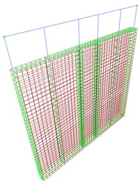
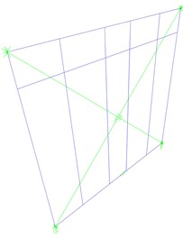
For present investigation, two different FE models were built for a 2950×2950 mm LFW wall (Fig. 1). The detailed model (Fig. 1(a)) was preliminary used to create a parameterized set of LFW walls, by varying the displacement ductility of the sheathing-to-frame connection, and to define the characteristics of the simplified model in Fig. 1(b). This last one was successively implemented in the three-dimensional assembly and each case-study building was analysed based on IDA.
Fig. 1a) Detailed and b) simplified FE models of the reference LFW shear wall
a)
b)
In the more detailed model (Fig. 1(a)), timber studs were modelled as pinned frames and the OSB panel as flat-shell elements. Non-linear links were used for hold-downs and angle brackets. The nailed connection was described by non-linear link. For the simplified and computationally efficient model (Fig. 1(b)), two diagonal nonlinear springs were used to reproduce the cyclic behaviour of sheathing-to-framing connection.
Both the detailed and simplified FE models were preliminary validated towards a full-scale laboratory test carried out on a 2950×2950 mm LFW shear wall [5].
The detailed model was hence used to parameterize LFW walls, by varying the ductility of the sheathing-to-framing connection, the nails spacing and the sides covered by OSB panel. In particular, the displacement ductility of the connection was evaluated by means of an Equivalent Energy Elasto Plastic (EEEP) approach [6], which was set equal to 4 (LDC) and 6 (HDC) respectively. To note that the selected values correspond to minimum requirements for Low and High Ductility Classes respectively, according to [7] and [2].
In the parameterisation process, starting from the calibrated force-displacement behaviour of the sheathing to frame connection, the yield and the ultimate displacements were modified, in order to match with the imposed ductility class. Furthermore, although the equivalent spring wall has the advantage of being less time-consuming during the FEM analyses, simplification leads to a loss of accuracy. In the transition from the detailed to the simplified model, in fact, the nail-by-nail behaviour of the connection is lost, and it is no longer possible to distribute the plasticization on each connector and follow its cyclic behaviour.
A further step in the research would be represented by the experimental verification of the parameterisation (by means of push-out test on the single connection or monotone/cyclic test on full-scale walls), testing a number of samples that consider not only the different ductility class, but also the resistance of the connection and the distribution of the connectors along the panels.
3. Case-study buildings
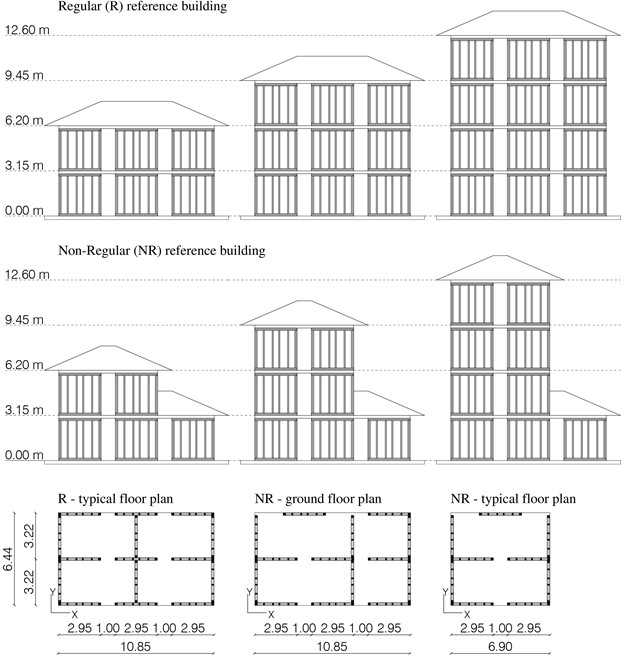
A set of six buildings with 2, 3 or 4 storeys was modelled assembling 2950×2950 mm walls (Fig. 2). Based on FE model validation, the size of experimental LFW shear wall was taken into account.
Three structures were designed as regular in plan and elevation, and the plan dimension (10.9×6.4 m) was kept constant at each level (Fig. 2(a)). Three other buildings were considered irregular in plan and in elevation. The non-regularity was evaluated based on Torsional Irregularity Ratio (TIR) [8], which is defined as the ratio of the drift at the building edge to the average drift. To note, according to [8], that a building is considered irregular when . In present study, the ground floor of non-regular buildings has the same dimensions of regular ones, but it is characterized by different arrangement of LFW walls, and the upper floors are reduced in plan dimension, to achieve a TIR greater than 1.2 (Fig. 2(b)).
All six buildings were designed in accordance with provisions from Eurocodes [2], [9]. The Life Safety ultimate state was verified by means of Eurocode response spectrum, with a Peak Ground Acceleration (PGA) of 0.35 g (soil type A and -factor equal to 3). Rossi et al. [4] showed that the soil type has a negligible influence on the ductility evaluation.
Fig. 2Elevation and plan view of buildings analysed by means of IDA approach (dimensions in m)
Furthermore, the -factor choice for design was strictly necessary to obtain reasonable structural dimensions for LFW walls. A -factor equal to 3, more in detail, affects the wall resistance only, because the nailed connection ductility was parameterized. Finally, the safety factors were set equal to 1 and a Capacity Design approach [10] was applied to hold-downs and angle-brackets, so that the whole energy dissipation could be allocated in the sheathing-to-framing connections.
4. IDA procedure
Papers in literature regarding the evaluation of the -behaviour factor for LFT buildings are mostly based on static non-linear pushover analyses, so that the cyclic behaviour of the connections is not taken into account. In this paper, instead, a dynamic approach was used.
IDA procedure [11] consists in a set of nonlinear dynamic analyses under a multiple-scaled series of ground motion records. In this study, ten couples of records were chosen by means of REXEL software [12], see Table 1.
Every IDA curve represents the relationship between the Engineering Demand Parameter (EDP) and the Intensity Measure (IM). In present work, the PGA was chosen as IM, while the ratio between the maximum roof displacement and the building height was selected as EDP (Roof Drift Ratio, RDR).
Table 1List of selected records for IDA procedure
Earthquake name | Date | (km) | PGAX (m/s2) | PGAY (m/s2) | |
Friuli Earthq 1st shock | 06/05/1976 | 6.4 | 22 | 3.390 | 3.090 |
L'Aquila Mainshock | 06/04/2009 | 6.3 | 5 | 5.352 | 6.442 |
Campano Lucano | 23/11/1980 | 6.9 | 16 | 1.526 | 1.725 |
Friuli (Aftershock) | 15/09/1976 | 6.0 | 14 | 3.395 | 3.296 |
Kalamata | 13/09/1986 | 5.9 | 11 | 2.354 | 2.670 |
Erzican | 13/03/1992 | 6.6 | 13 | 3.814 | 5.028 |
Umbria Marche | 26/09/1997 | 6.0 | 11 | 5.138 | 4.538 |
Montenegro | 15/04/1979 | 6.9 | 25 | 4.453 | 3.000 |
South Iceland | 17/06/2000 | 6.5 | 15 | 2.038 | 4.678 |
Bam (Iran) | 26/12/2003 | 6.5 | 6 | 7.848 | 6.278 |
The choice of (PGA, RDR) couple allows to compare IDA curves at the same scale for each ductility class, and for each number of storeys, while does not affect the evaluation of corresponding -factor, which was estimated as the ratio of base shear forces.
Among different literature procedures to obtain [13], the approach proposed by Mwafy and Elnashai [14] was used in present study. The behaviour factor was thus evaluated as the product between a ductility factor and an overstrength factor :
To note that the factor depends on the non-linear behaviour of the structure, while accounts for its over-strength, due to structural redundancy and post-elastic hardening. Also, is the base shear corresponding to building collapse, while is the base shear obtained by elastic analysis of the structure under the same records. Finally, is the base shear corresponding to first yielding and is evaluated by means of a static non-linear analysis. The yield point of walls was calculated according to the EEEP approach [6].
As a major assumption of present study, it is worth noting that the -factor from Eq. (1) is “intrinsic”, because obtained imposing all safety factors equal to 1.
5. Results
The results of IDA procedure are shown in Fig. 3 for each ductility class and for each number of storeys for both regular (black line) and non-regular (red line) buildings.
Regular and non-regular structures, as shown, exhibit similar behaviour, achieving comparable drift and PGA. However, results for the non-regular case are more dispersed, especially in Fig. 3(c, d, e), where some irregular buildings reach higher PGA values at collapse, compared to the corresponding regular ones.
The collected parametric results were hence used to evaluate the -factor by means of Eq. (1). Nevertheless, it is important that a direct comparison of present values and those provided by design codes is not possible. In the present investigation, the overstrength factor for sheathing-to-frame connection was in fact set to 1. Though, it is possible to multiply the “intrinsic” by 1.5 (which corresponds to the -factor suggested by Eurocode 8 for a global non-dissipative behaviour) to calculate the code dependent -factor , see Table 2.
The average factor, which depends on the structural ductility, is the same for the two cases (1.6 and 1.8 for ductility class 4 and 6), but the dispersion is higher in the non-regular case. On the other hand, the overstrength factor is lower for the regular case. In conclusion, the overall comparative results highlighted similar values for both regular and non-regular buildings.
Fig. 3IDA studies for ductility class 4 (a, b, c) and 6 (d, e, f) for each number of storeys (black line: regular building; red line: non-regular building)
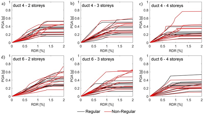
Table 2Average value (Avg) and CoV of the q-behaviour factors for each case
Avg | CoV | Avg | CoV | Avg | CoV | Avg | CoV | ||
R | duct4 | 1.6 | 0.19 | 1.2 | 0.16 | 1.9 | 0.30 | 2.9 | 0.30 |
duct6 | 1.8 | 0.23 | 1.2 | 0.14 | 2.3 | 0.29 | 3.4 | 0.29 | |
NR | duct4 | 1.6 | 0.24 | 1.3 | 0.15 | 2.1 | 0.25 | 3.1 | 0.25 |
duct6 | 1.8 | 0.29 | 1.3 | 0.15 | 2.3 | 0.31 | 3.5 | 0.31 | |
For a ductility class equal to 4, values equal to 2.9 (R) and 3.1 (NR) respectively were in fact obtained from present investigation, which confirm the 3.0 provision in the Italian building code [7] for LDC timber structures.
On the other hand, values equal to 3.4 (R) and 3.5 (NR) were obtained for a ductility class 6, which is widely lower than 5, as suggested for DCH by both Eurocode 8 [2] and Italian building code [7]. In this sense, the present investigation suggests that the imposed structural irregularity does not seem to strongly affect the global factor. However, it is worth noticing that this result comes from a preliminary parametric study, and that both the number of case-study buildings and analyses should be further extended to draw robust conclusions.
6. Conclusions
In this paper, an Incremental Dynamic Analysis (IDA) approach was used for the evaluation of the -behaviour factor for Light-Frame Timber (LFT) buildings. A total of six buildings were analysed to assess the influence of structural non-regularity (in plan and elevation), by varying the displacement ductility of the sheathing-to-framing connection.
It is well known that regular structures represent the best solution towards seismic excitation. However, these first results highlighted – although preliminarily – a rather negligible effect of non-regularity on the global -factor for low- and mid-rise timber buildings. Apparently, the presence of irregularity reflects in the dispersion of ductility factor only, which is higher for non-regular cases. Still, this evidence is the first result from an extended study in progress. In the following, additional irregular configurations will be analysed, with significantly larger number of analyses.
References
-
A. Mishra et al., “Land use change and carbon emissions of a transformation to timber cities,” Nature Communications, Vol. 13, No. 1, pp. 1–12, Aug. 2022, https://doi.org/10.1038/s41467-022-32244-w
-
Deepak Shrestha, “Eurocode 8: Design of structures for earthquake resistance – Part 1: General rules, seismic actions and rules for buildings,” Brussels, Belgium, CEN, European Committee for Standardization, 2013.
-
B. Faggiano et al., “The Italian instructions for the design, execution and control of timber constructions (CNR-DT 206 R1/2018),” Engineering Structures, Vol. 253, p. 113753, Feb. 2022, https://doi.org/10.1016/j.engstruct.2021.113753
-
S. Rossi, I. Giongo, D. Casagrande, R. Tomasi, and M. Piazza, “Evaluation of the displacement ductility for the seismic design of light-frame wood buildings,” Bulletin of Earthquake Engineering, Vol. 17, No. 9, pp. 5313–5338, Sep. 2019, https://doi.org/10.1007/s10518-019-00659-4
-
A. Gubana and G. Tomasi, “Results analysis of an experimental shear test on a light frame timber wall,” (in Italian), Technical Report UNIUD 01, Reluis project 2010-2013, 2013.
-
“Standard test methods for cyclic (Reversed) load test for shear resistance of vertical elements of the lateral force resisting systems for buildings,” American Society Standard Method (Astm) E. 2126-11, 2018.
-
“Italian Building Code NTC 2018,” (in Italian), Ministerial Decree of 17th January 2018, 2018.
-
Minimum Design Loads and Associated Criteria for Buildings and Other Structures. Reston, VA: American Society of Civil Engineers, 2017, https://doi.org/10.1061/9780784414248
-
“Eurocode 5: design of timber structures-part 1-1: general-common rules and rules for building,” En 1995-1-1:2005, 2013.
-
D. Casagrande, T. Sartori, and R. Tomasi, “Capacity design approach for multi-storey timber-frame buildings,” in 1st. International Network on Timber Engineering Research (INTER) Meeting 1, 2014.
-
D. Vamvatsikos, “Incremental dynamic analysis,” Encyclopedia of Earthquake Engineering, Vol. 31, No. 3, pp. 1–8, 2014, https://doi.org/10.1007/978-3-642-36197-5_136-1
-
I. Iervolino, C. Galasso, and E. Cosenza, “REXEL: computer aided record selection for code-based seismic structural analysis,” Bulletin of Earthquake Engineering, Vol. 8, No. 2, pp. 339–362, Apr. 2010, https://doi.org/10.1007/s10518-009-9146-1
-
A. Ceccotti, M. Massari, and L. Pozza, “Procedures for seismic characterization of traditional and modern wooden building types,” International Journal for Quality Research, Vol. 10, No. 1, pp. 47–70, 2016, https://doi.org/10.18421/ijqr10.01-02
-
A. M. Mwafy and A. S. Elnashai, “Calibration of force reduction factors of RC buildings,” Journal of Earthquake Engineering, Vol. 6, No. 2, pp. 239–273, Apr. 2002, https://doi.org/10.1080/13632460209350416
About this article

This research work was partly financed by the ReLUIS Consortium (Italian University Network of Seismic Engineering Laboratories), within the frame of the ReLUIS-DPC 2022-2024 project WP13 “Timber Structures – Code contributions”.
The datasets generated during and/or analyzed during the current study are available from the corresponding author on reasonable request.
The authors declare that they have no conflict of interest.
