Abstract
Magneto rheological elastomer (MRE) is a smart material consists of a polymer matrix embedded micro/nano-sized magnetic particles. Its mechanical properties are altered by external magnetic fields. In this article, a magnetic-mechanical coupled physics is done for MRE using COMSOL multi-physics finite element analysis (FEA) software for a particle level (micro-scale). Both linear and torsional transmissibility analysis are done on MRE under influence of magnetic fields. Simulation results indicate both linear and torsional stiffness increased with magnetic field. Under the initial influence of magnetic field, it is shown that an increase of 28.75 % and 20.12 % of the stiffness in linear and torsional modes, respectively. Transmissibility curve showed shift in the natural frequency due to increase in stiffness when exposed to a magnetic field. Vibration isolation was reached by achieving a minimum transmissibility factor.
Highlights
- In this article, a magnetic-mechanical coupled physics is done for MRE using COMSOL multi-physics finite element analysis (FEA) software for a particle level (micro-scale).
- Both linear and torsional transmissibility analysis are done on MRE under influence of magnetic fields.
- Under the initial influence of magnetic field, it is shown that an increase of 28.75 % and 20.12 % of the stiffness in linear and torsional modes, respectively.
- Transmissibility curve showed shift in the natural frequency due to increase in stiffness when exposed to a magnetic field.
- Vibration isolation was reached by achieving a minimum transmissibility factor.
- Results can be used to predict the behaviour of MRE by extrapolating the scale of MRE. The novelty in this work is reaching the particle level of the MRE.
1. Introduction
Magneto-rheological elastomer (MRE) is a smart composite material that consists of a non-magnetizable polymer matrix embedded with micro/nano-sized ferromagnetic particles. These materials are able to alter their mechanical properties such as elasticity and stiffness when exposed to an external magnetic field [1, 2]. This property makes them attractive to many engineering applications such as dampers, vibration isolators, sensors, and magneto-rheological elastic polishing bodies [3-6]. The polymer matrix is mixed with the magnetic particles and then it is vulcanized at a high temperature (120 °C) where the particles can move inside the polymer matrix; this process is called curing which is done with or without magnetic. Anisotropic MREs are materials where the magnetic particles are arranged uniformly after applying the magnetic field during manufacturing. On the other hand, isotropic MREs contain these particles in a random distribution when no magnetic field is applied. Fig. 1 shows the curing process of MREs.
Fig. 1The preparation of MRE [7]
![The preparation of MRE [7]](https://static-01.extrica.com/articles/21377/21377-img1.jpg)
The internal magnetic particles which form like a chain in the direction of the magnetic field are the main factor in determining the mechanical properties of these elastomers [8]. The better arrangement of particles by controlling the magnetic field, the better mechanical properties obtained of MRE [9]. Therefore, for better understanding of the characterization of MRE and how stiffness properties are varied with varying the magnetic field; further study on its behavior is needed. The main focus when studying MRE numerically is on the magnetic particles such as type of particles, particle size, volume fraction of the particles and the influence of the magnetic field on the chain formed by these particles [10-12]. MREs are firstly reported by Rigibi and Jiklen in 1983 [13]. Recently, the most widely used MREs are the micron-sized carbonyl iron powder invented by BASF in 1925 [14]. For the polymer elastic matrix, there are lots of polymeric rubbers such as natural rubber, silicone rubber, and poly dimethylsiloxane (PDMS) [15-17]. MRE in microscopic scale is studied extensively in theory and experiments. An investigation of a positive MR effect such that the elastic modulus has increased by applying a magnetic field for unstructured magnetic field [18]. [19] has found a strong effect for materials with structured particles distribution. Furthermore, the work of [9] illustrated a strong dependence of the MR effect on applied mechanical preloads. The static and quasi-static behaviour of the MRE for semi-active vibration control is investigated [20], where a direct proportional relationship between the MRE resisting force with the applied magnetic field, velocity and displacement. The performance of MRE in torsional vibration control is studied by which a shifting in the excitation frequency was observed in the transmissibility curves at different applied magnetic field [21]. Some analytical models of MRE has been studied by [22] in order to observe their hysteresis behaviour and to plot the transmissibility curve vs frequency.
The finite element analysis (FEA) is the most widely used method for solving problems of mathematical and engineering models. The FEA is a numerical method for solving partial differential equations (PDEs) in 2D or 3D [23]. FEA has been applied in some studies to simulate the MRE. FEA results showed an innovative magnetic design which is able to provide sufficient and uniform magnetic field to all 25 MRE layers for base isolator presented in [24], it is found that the magnetic field in MRE materials deteriorates when the deformation of the device increases. According to the 2D model of [25], in a microscopic view, the anisotropic MRE unit cell contract under the presence of a magnetic field which results in increased stiffness of the material. This situation is verified in a 3D RVE model by [26]. A simulation of magneto-rheological elastomer (MRE) composite beams made of Barium hexaferrite (BaM) and Iron (Fe) powders combined with a highly-compliant matrix material [27], this is done using COMSOL Multiphysics and developed models are shown to be capable of predicting the actuation behaviour of hard- and soft-magnetic MREs. [28] has showed a numerical implementation of a model for rate-dependent magneto-active polymer to get the response of a large deformation magneto-mechanics. A numerical study using FEA was done to investigate the deformation dependent behaviour of MRE with structured and unstructured distributions of particles [29]. Their findings support the idea that an interaction of particles in wavy chains is responsible for their macroscopic behaviour. [30] used multiphysics module in FEA software ANSYS to analyse Magnetorheological elastomer isolator of Static magnetic field and modal analysis. Static magnetic field analysis demonstrates that the Magnetic field caused by coil can meet the requirements of design. Results show that the results calculated by ANSYS are in good agreement with the analytical values. An adaptive component in the design of vibration absorber using magnetorheological elastomers (MREs) as the adaptive spring was developed by [31]. The vibration mode of a simple model of automobile engine is simulated by Finite Element Method (FEM) analysis. Simulation results indicate that the control frequency of Adaptive Tuned Dynamic Vibration Absorber (ATDVA) can be changed by modifying the shear modulus of MREs and the vibration reduction efficiency.
In this paper, a finite element analysis is done for MRE using COMSOL software. This is to observe how the stiffness of this material is varied by applying an external magnetic field and to obtain the transmissibility with respect to harmonic excitation frequency. This analysis is done for linear (axial) and torsional modes. This paper contributes to investigate and study the behaviour of MRE in 3D using a numerical method. The cylindrical silicon elastomer is embedded with magnetic particles. In addition, the geometry is modelled in the micro-scale in order to visualize the behaviour of MRE under magnetic field. This study is interested in reaching the particle level of the MRE so that the influence of the magnetic field on the micro particles is investigated. The stiffness in both modes is studied under the influence of the magnetic field. Also, the transmissibility analysis is done in order to observe the field-stiffening characteristics.
This article is outlined as follows. Section 1 gives an introduction and background about the MRE and its applications. In addition, it reviews the FEA basics and different simulations studies that used MRE numerically. Section 2 illustrates the numerical model of the proposed MRE in this numerical study; it covers the governing equations used by COMSOL and equations used to calculate stiffness and the transmissibility factor. Section 3 focuses on the methodology followed to simulate the problem by COMSOL and illustrates the boundary conditions for both linear and torsional modes. This paper ends with Section 4 which discusses all results found in the study. Finally, Section 5 gives an overall conclusion about the simulation study.
2. Numerical model of MRE
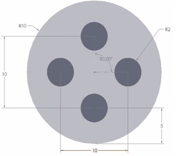
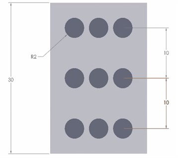
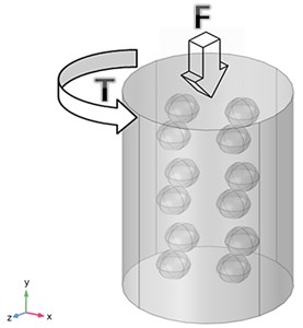
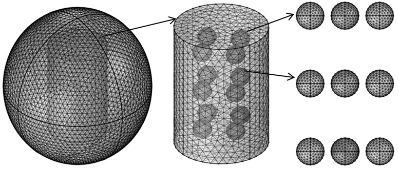
3D model of MRE is developed it consists of two main regions: a MRE and the surrounding air region as in Fig. 2. The model is a cylinder which is a pure silicon rubber and 12 iron particles (spheres) which are distributed in an anisotropic orientation. The cylindrical silicon rubber has a diameter of 20 μm and a height of 30 μm. The iron particles are spheres with 4 μm in diameter for each. The geometry of the proposed MRE and its dimensions are illustrated in Fig. 3.
Fig. 2MRE 3D model
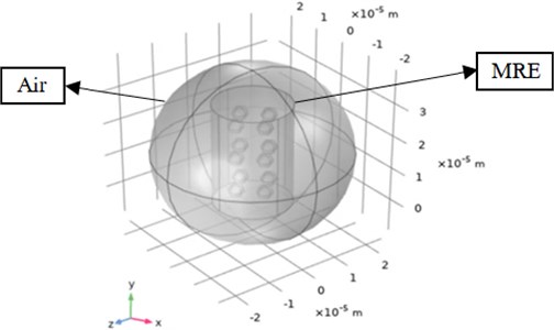
Fig. 3Dimensions of the MRE model used in the simulation study in µm
The mechanical and magnetic properties of the MRE are chosen from literature studies [28-30]. For the MRE, silicon rubber is imported from COMSOL library to be the polymer matrix and the particles are set to be “iron powder vetroferrit” due to good magnetic behaviour and the high permeability. The properties for the MRE for the analysis are obtained where Young’s modulus is defined for both the rubber and the magnetic particles. The material properties used for this simulation study are shown in Table 1.
Table 1Materials properties of the MRE
Silicon | Density [kg/m3] | 1100 |
Relative permeability | 2 | |
Relative permittivity | 4 | |
Young’s modulus [MPa] | 0.12 | |
Poisson’s ratio v | 0.31 | |
Dynamic viscosity [kg/ms ] | 0.00086 | |
Iron powder vetroferrit | Young’s modulus [MPa] | 200000 |
Poisson’s ratio | 0.33 | |
Air | Relative permeability | 1 |
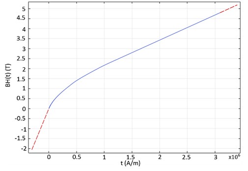
For the iron magnetic particles, the H-B curve expansion for this material (Iron powder vetroferrit) is obtained from COMSOL materials library as shown in Fig. 4 [35]. It shows the magnetization properties of the iron particles and how it’s saturated under a magnetic field. Since torque is applied on the MRE to get it is torsional stiffness properties; the shear modulus should be known. An equation for the shear modulus of a rubber that is filled with particles as follows [36]:
where is the shear modulus of pure silicon rubber ( 50.9 GPa [33] and is the volume fraction of particles relative to the rubber matrix and it can be expressed in this case by:
where is the radius of the particles, is the number of particles, is the radius of the rubber cylinder and is the height of the rubber cylinder. The volume fraction of the model is 4.27 % and hence, the shear modulus for MRE is 57.7 GPa.
Fig. 4H-B curve expansion for the Iron powder vetroferrit
2.1. Governing equations
The continuum-mechanics approach is used to analyze the MRE by which the mechanical deformation equations are coupled with electromagnetic equations. A set of partial differential equations are solved using COMSOL. In this case, it is assumed that an external force per unit area is applied at the top surface of MRE for the linear analysis, by applying Newton’s 1st law of motion, the stress distribution within the cylinder in as follow in tensor notation:
The generalized Hooke’s law:
where is linear Cauchy stress tensor, is the modulus of elasticity. But Hooke’s law for springs, the linear stiffness:
where is the force, is the linear stiffness and is the deformation in -axis. The tensor notation of linear strain displacement:
Substituting Eqs. (4-6) into Eq. (3), the governing equation becomes:
Similarly, for the torsional analysis, Hooke’s law becomes:
where is the torsional stress tensor, is the shear modulus and is the torsional strain. The torsional stiffness of MRE for can be obtained from:
where is torque applied, is the torsional stiffness, and is the rotation. Therefore, the governing equation for the torsional analysis becomes:
The previous sets of equations solve the solid structure aspect for the magneto-mechanical problem. The following equations solve for the “external magnetic field interface with no current”:
where is the relative permeability of the material, 4×10⁻⁷ N/A2 is the permeability of free space, is the magnetic field, is the background magnetic field and is the magnetic potential vector. For each material; silicon rubber, particles and air, there is a different relationships based on the relative permeability. The general constitutive relation for the magnetic behaviour of air medium is:
where is the magnetic flux intensity. The general constitutive equation for the iron particles (magnetic material) is given by:
where is the magnetization. The magnetostriction physics equation becomes:
After that, the frequency domain analysis is done to get the linear amplitude transmissibility (), the input is applied as a displacement, to get output displacement response expressed by:
where is the input harmonic displacement, is the amplitude, is the harmonic displacement response, is the response amplitude, or is imaginary number, is the time, is the angular frequency [rad/s]. The linear amplitude transmissibility () is plotted with respect to the excitation frequencies. Similarly, for the torsional transmissibility (), the equations becomes:
where is the input harmonic rotation, is the rotational input amplitude, is the harmonic displacement response, is the rotational response amplitude.
3. COMSOL Multi-physics simulation
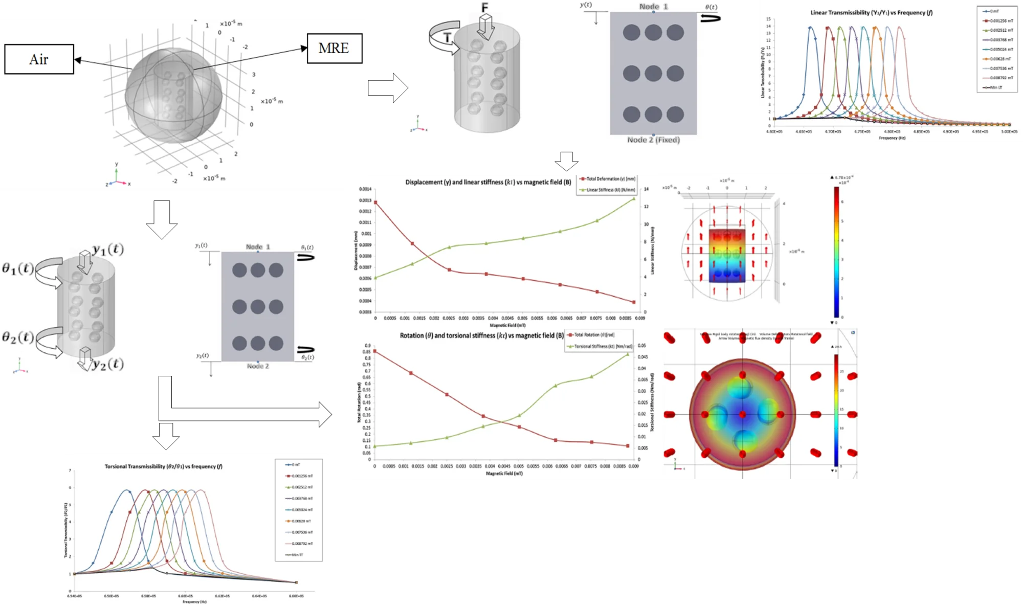
This multi-physics simulation is to study the mechanical behaviour of the MRE in the presence of a magnetic field on the particle scale of MRE. Such analysis is to study the variation in stiffness due to the magnetic field and its effect on transmissibility curve for both linear and torsional vibration. The magneto-elastic coupled interface simulation using Solid structure and magnetic field physics is done.
This study is divided into two parts; the 1st part is to obtain the stiffness of the system in linear and torsional modes, by which a fixed load/torque is applied on the top surface of the MRE, and then obtaining the deformation/rotation of the system under various magnetic fields and then calculating the linear/torsional stiffness using Eqs. (5, 9). The 2nd part of the analysis is to obtain the transmissibility curve with respect to the frequency using a harmonic study under different magnetic fields. The resonance frequencies are obtained using the Eigen frequency study, and then the harmonic study is done for a range of frequency covering the fundamental natural frequency of the system for linear and torsional cases.
3.1. Methodology and boundary conditions
3.1.1. Methodology and boundary conditions for stiffness analysis
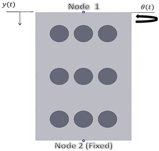
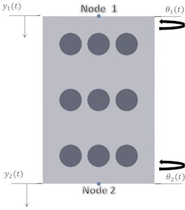
In this subsection, the mechanical boundary conditions in 2D and 3D of the system are represented in Fig. 5. The upper top surface of the MRE has a boundary load; a force in the –-axis as in Fig. 5(a) for the linear analysis and a torque using a rigid connector (counter clockwise) around +-axis. On the other hand, the lower bottom surface is fixed. This is done to calculate the stiffness of the system after obtaining the deformation/rotation at different values of magnetic field using Eqs. (5, 9). The values of loads are constant in each iteration. A parametric sweep is done for the magnetic field strength from 0 A/m – 7 A/m with a step of 1 A/m. For each value, the deformation/rotation is noted to be analysed.
Fig. 5(a) represents the boundary loads for both linear and torsional load on the top surface of the MRE in 3D while Fig. 5(b) illustrates the boundary conditions in 2D. Assuming two nodes in each side of MRE; node 1 and node 2, the boundary conditions for the linear analysis can be represented by the displacement applied in a function of force applied and where is the displacement (deflection) in -direction and the linear load is –0.005 N. Similarly, for torsional analysis the rotation applied as a function of the torque and 0 where the rotation around -axis and the torque applied is 0.005 N.m. However, the displacement/rotation will depend also on the magnetic field applied. Therefore, and .
Fig. 5Methodology and boundary conditions representation for 1st part in a) 3D and b) 2D
a)
b)
3.1.2. Methodology and boundary conditions for transmissibility curve analysis
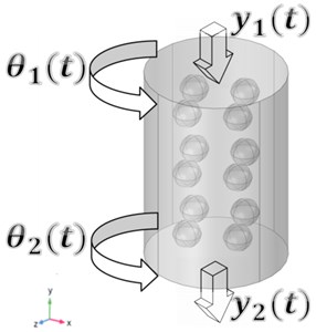
In this case, the bottom surface (node 2) of the MRE is free end, so that it can displace/rotate. However, the load/torque applied on the top surface are now harmonic loads at certain range of excitation frequencies; Eqs. (17-20) illustrates the methodology followed by COMSOL to solve the analysis. This methodology is shown in Fig. 6(a) in 3D and Fig. 6(b) in 2D. The analysis is mainly to find the transmitted loads on the bottom surface of the MRE (Node 2). These loads are axial load (linear displacement) to study the linear amplitude transmissibility and torsional load (rotation) to study the torsional amplitude transmissibility.
Fig. 6Methodology and boundary conditions representation for the transmissibility analysis in a) 3D and b) 2D
a)
b)
The boundary conditions are excitations harmonic loads applied. In case of linear transmissibility, the amplitude 0.005 N is given as a harmonic input to the system. Similarly, a rotation 0.35 rad. Similar to the previous study, a parametric sweep is done for the magnetic field strength from 0 A/m-7 A/m with a step of 1 A/m. For each value, the deformation/rotation at node 2 (output) is divided by the input value for the transmissibility curve with respect to the excitation frequencies. The transmissibility obtained in this study is based mainly on the behaviour of the stiffness of the MRE as the magnetic field is varied. The frequencies ranges for the harmonic analysis are obtained after conducting an Eigen frequency study by COMSOL.
3.2. Meshing
Meshing is done using COMSOL physics-controlled mesh. The element size is set to be extra fine. The total number of elements of the mesh is 349236 elements which is a significant number for a micro-scale model. 53774 elements are in the iron particles, 118351 elements are in the silicon rubber matrix and 177111 elements are in the air domain sphere. A good mesh quality is identified by some statistical measures. For example, from the mesh statistics, skewness is chosen from the quality measure tab which is defined by the angular measure of the quality of elements, it also illustrates how ideal is a cell or a face [37]. As a rule of thumb, the minimum element value in the skewness statistics is above 0.01 [36]. The value in this mesh is 0.6626. Therefore, it is concluded that the mesh is significant for the study. Meshing for MRE is shown in Fig. 7.
Fig. 7Mesh of the MRE model
4. Results and discussion
In this analysis, a magneto-mechanical coupling finite element formulation and simulation of MRE is presented using COMSOL. MRE is modelled as cylindrical silicon rubber embedded with 12 spherical magnetic particles (Iron powder vetroferrit), and a sphere around it which considered to be the air domain. Two types of studies are done; the 1st study is to investigate the variation in the linear/torsional stiffness of MRE when an external magnetic field is applied. The 2nd study is to plot the transmissibility curve of both linear and torsional harmonic loads.
Firstly, the magnetic behaviour of the particles is identified by a B-H curve which describes the magnetic flux density (B) with respect the magnetic field strength (H). COMSOL identifies the magnetic field strength (H) in A/m and the magnetic flux density (B) in T, the applied magnetic field strength is a sweep from 0 A/m to 7 A/m using “Magnetic fields, no current” physics in COMSOL. However, results are shown in terms of magnetic flux density (B) in mT. This conversion is done using Eqs. (14-16) depending on the materials relative permeability and data are represented in Table 2. Fig. 8 shows the internal magnetic forces for the particles as they are trying to attract to each other. Therefore, it can be concluded that particles tend to get closer to each other so that the stiffness properties of the MRE are varied at different magnetic field strength.
Fig. 8Arrow volume plot showing the inner attractive forces by the magnetic particles
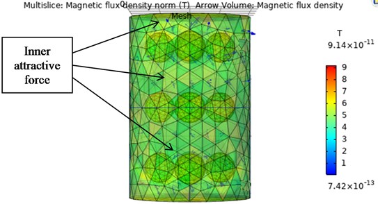
Table 2Magnetic flux intensity calculations
Magnetic field strength [A/m] | 0 | 1 | 2 | 3 | 4 | 5 | 6 | 7 |
Magnetic flux density [mT] | 0 | 0.001256 | 0.002512 | 0.003768 | 0.005024 | 0.00628 | 0.007536 | 0.008792 |
Fig. 9Volume displacement of the MRE for –0.005 N at a magnetic field of a) 0 mT and b) 0.002512 mT
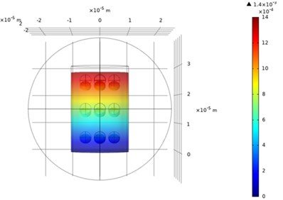
a)
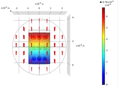
b)
The 3D plot of the deformed and undeformed MRE is shown in Fig. 9. In Fig. 9(a), the force of 0.005 N is applied on the upper surface (node 1) with 0 T and the deformation plot of the displacement field and magnetic flux density arrows is shown. The lower surface (node 2) is fixed, from the range of the maximum displacement the value of the deformation 1.4 µm. On the other hand, the same approach is done while an external magnetic field is applied in the +–axis ( 0.002512 mT) as Fig. 9(b). The deformation is 0.678 µm. It can be concluded that the displacement is decreased when the magnetic field is applied. This proves that the stiffness has increases and hence, the displacement decreases.
This analysis is done for different values of the magnetic field; a parametric sweep is done in COMSOL to repeat the simulation at values from 0 mT to 0.008792 mT of magnetic field. The displacement values are obtained and the linear stiffness is calculated using Eq. (5). Similarly, for the torsional stiffness using Eq. (9), the rigid body rotation as a top view is shown in Fig. 10. It can be clearly seen that in the when the magnetic field of 0.002512 mT is applied, the range of the rotation along y-axis indicates that the rotation (angle) has been reduced from 49.2° to 29.5°. The torsional stiffness has a direct proportionality with the magnetic field. This simulation has been repeated for a magnetic field of 0 mT to 0.008792 mT. The comparison in both linear/torsional deformation with/without the magnetic field is chosen when 0.002512 mT, and this due to the proper size of the arrows. The arrows represent the magnitude of the external magnetic field that affects the system.
Fig. 10Rigid body rotation of the MRE for 0.005 N.m at a magnetic field of a) 0 mT and b) 0.002512 mT
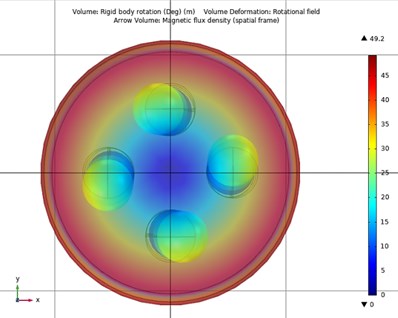
a)
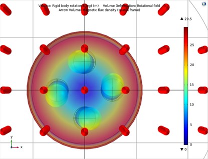
b)
Fig. 11Displacement (along y-axis) and linear stiffness vs. magnetic field plot
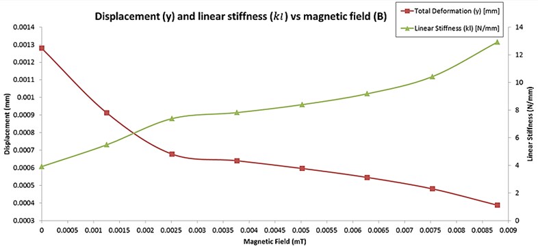
Fig. 12Rotation (about y-axis) and torsional stiffness vs. magnetic field plot
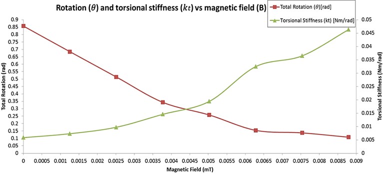
The simulation is done for different values of magnetic fields and the stiffness in both modes are calculated. Fig. 11 shows the plot of the linear stiffness and displacement with respect to the magnetic field at constant force applied at node 1, the linear stiffness increases with the magnetic field. The linear stiffness has shown 28.75 % increase when the 1st magnetic field is applied ( 0.001256 mT). The maximum stiffness reached is 12.9 N/mm ( 0.008792 mT) while the minimum stiffness is 3.9 N/mm ( 0 mT). Hence, the displacement is changed when the stiffness of the MRE is also changed. When there is no magnetic field, the displacement at node 1 is 0.00128 mm while it reached 0.000387 mm when the magnetic field is 0.008792 mT. For torsional stiffness, results show similar trend. The torsional stiffness increases when the magnetic field increase while rotation decreases as in Fig. 12. The torsional stiffness has shown 20.12 % increase when the 1st magnetic field is applied ( 0.001256 mT). The maximum and minimum stiffness are 0.04629 N.m/rad ( 0.008792 mT) and 0.00583 N.m/rad ( 0 mT), respectively. The rotation is measured by the angle on the upper surface of the MRE after applying the constant torque on it ( 0.005 N.m). The angle is obtained from COMSOL in degrees and is converted to radians, the angle changed from 0.857 rad 0 mT) to 0.108 rad ( 0.008792 mT). Therefore, it can be concluded that the stiffness of MRE in linear and torsional modes increases as the magnetic field is higher.
Fig. 13Transmissibility curve for linear amplitude harmonic excitation at different magnetic field strength
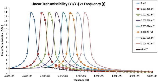
Fig. 14Transmissibility curve for torsional amplitude harmonic excitation at different magnetic field strength
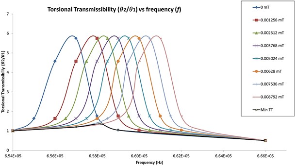
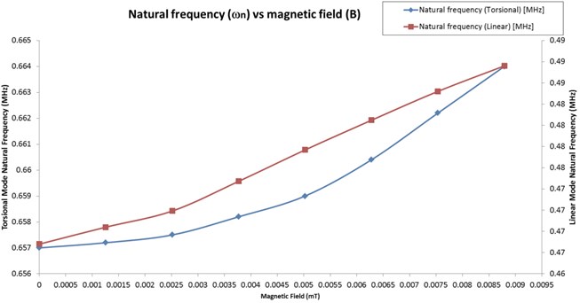
The second part of the analysis is to find the transmitted load for the MRE when it is excited harmonically. The input harmonic load is applied on the upper surface (node 1) of the MRE and the response on the lower surface is obtained using Eqs. (17-20). The input in both linear and torsional modes is harmonically excited at a range of excitation frequencies. The fundamental frequency obtained for the linear load is 0.466 MHz while 0.657 MHz for the torsional mode. The values are very large due to the micro scaling of MRE. The mass is very small so the frequency is high. Therefore, the excitation loads in both modes are applied at a certain range of frequencies which covers the resonance frequency. Figs. (13, 14) show the transmissibility curve for the linear and torsional amplitude transmissibility at different magnetic field values. The transmissibility curves are moving to the right and a shift in the natural frequency of the system is observed when the magnetic field increases. The shifting in the natural frequency of the system in both modes indicates that the MRE is becoming stiffer; this stiffening effect on MRE is due to the magnetic field. The values of the natural frequency for both linear and torsional modes with respect to the magnetic field are shown in Fig. 15. The natural frequency increases when the magnetic field increases as well. When no magnetic field is applied, the natural frequency of the linear transmissibility is 0.466 MHz, when the magnetic field is applied, the natural frequency increased until it reached 0.483 MHz ( 0.008792 mT). Similarly, the natural frequency of the torsional mode is 0.657 MHz without magnetic field and it reached 0.661 MHz for the maximum magnetic field ( 0.008792 mT).
Fig. 15Natural frequency vs magnetic field
The damping ratio of the MRE is almost constant as the peaks of the transmissibility curves are constant because the concern in this model is more focused on the stiffness of the MRE. From Fig. 13, when there is no magnetic field applied ( 0 mT), the 1st natural frequency occurs at 0.466 MHz with a linear transmissibility factor of 13.7. Then, at the same frequency value, with 0.001256 mT applied magnetic field, the transmissibility factor reduces to 2.1. Therefore, as the value of the magnetic field increases, the transmissibility factor decreases. Similarly, for the torsional transmissibility curves, as in Fig. 14, as the value of the magnetic field increases, the magnitude decreases. The minimum transmissibility factor that can be achieved is indicated in black dotted lines in both linear transmissibility (Min LT) and torsional transmissibility (Min TT). This indicates that an excitation frequency can be achieved by changing the magnetic field, hence, the stiffness of the MRE.
5. Conclusions
MRE is an evolving field. In this work, MRE is modelled in an anisotropic distribution as a silicon rubber embedded with magnetic particles. MRE properties such as stiffness variation with the magnetic field are studied numerically. In addition, a harmonic study simulation is done in order to plot the transmissibility curve. MRE is studied in both linear and torsional modes. Results showed that the MRE becomes stiffer in both modes when the magnetic field is higher due to the internal forces of the magnetic particles that tend to be attracted to each other. When the 1st magnetic field strength is applied, an increase of 28.75 % and 20.12 % is observed in the linear and torsional stiffness, respectively. In addition, the transmissibility curve is shifting towards the right indicating that the natural frequency of the system is changed, this shifting is due to the fact that MRE is becoming stiffer. A minimum value of transmissibility factor can be achieved at a certain excitation frequency by changing the magnetic field which leads to vibration isolation. Results obtained in this work can be verified by the theory of the stiffness change under a magnetic field from the literature. Results show that the stiffness in both modes increases with the magnetic field and reversely the deformation/rotation. In addition, the transmissibility curve shifting is obtained which agrees with the literature that the natural frequency of the system increases. Results can be used to predict the behaviour of MRE by extrapolating the scale of MRE. The novelty in this work is reaching the particle level of the MRE to visualize its behaviour under a magnetic field.
References
-
Jolly M. R., Carlson J. D., Muñoz B. C., Bullions T. A. The magnetoviscoelastic response of elastomer composites consisting of ferrous particles embedded in a polymer matrix. Journal of Intelligent Materials Systems and Structures, Vol. 7, Issue 6, 1996, p. 613-622.
-
Chen L., Gong X. L., Jiang W. Q., Yao J. J., Deng H. X., Li W. H. Investigation on magnetorheological elastomers based on natural rubber. Journal of Materials Science, Vol. 42, Issue 14, 2007, p. 5483-5489.
-
Bastola A. K., Li L. A new type of vibration isolator based on magnetorheological elastomer. Materials and Design, Vol. 157, 2018, p. 431-436.
-
Kumbhar S. B., Chavan S. P., Gawade S. S. Adaptive tuned vibration absorber based on magnetorheological elastomer-shape memory alloy composite. Mechanical Systems and Signal Processing, Vol. 100, 2018, p. 208-223.
-
Bica I. Magnetoresistor sensor with magnetorheological elastomers. Journal of Industrial and Engineering Chemistry, Vol. 17, Issue 1, 2011, p. 83-89.
-
Xu Z., Wang Q., Zhu K., Jiang S., Wu H., Yi L. Preparation and characterization of magnetorheological elastic polishing composites. Journal of Intelligent Materials Systems and Structures, Vol. 30, Issue 10, 2019, p. 1481-1492.
-
Liu T., Xu Y. Magnetorheological elastomers: materials and applications. Smart and Functional Soft Materials, IntechOpen, 2019.
-
Boczkowska A., Awietj S. Microstructure and properties of magnetorheological elastomers. Advanced Elastomers – Technology, Properties and Applications, InTech, 2012.
-
Danas K., Kankanala S. V., Triantafyllidis N. Experiments and modeling of iron-particle-filled magnetorheological elastomers. Journal of the Mechanics and Physics of Solids, Vol. 60, Issue 1, 2012, p. 120-138.
-
Perales Martínez I.-A., Palacios Pineda L.-M., Lozano Sánchez L.-M., Martínez Romero O., Puente Cordova J.-G., Elías Zúñiga A. Enhancement of a magnetorheological PDMS elastomer with carbonyl iron particles. Polymer Testing, Vol. 57, 2017, p. 78-86.
-
Liu T., Gong X., Xu Y., Xuan S., Jiang W. Simulation of magneto-induced rearrangeable microstructures of magnetorheological plastomers. Soft Matter, Vol. 9, Issue 42, 2013, p. 10069-10080.
-
Li J., Gong X., Xu Z., Jiang W. The effect of pre-structure process on magnetorheological elastomer performance. Zeitschrift fuer Metallkunde/Materials Research and Advanced Techniques, Vol. 99, Issue 12, 2008, p. 1358-1364.
-
Rigbi Z., Jilkén L. The response of an elastomer filled with soft ferrite to mechanical and magnetic influences. Journal of Magnetism and Magnetic Materials, Vol. 37, Issue 3, 1983, p. 267-276.
-
Japka J. E. Microstructure and properties of carbonyl iron powder. JOM, Vol. 40, Issue 8, 1988, p. 18-21.
-
Li W. H., Nakano M. Fabrication and characterization of PDMS based magnetorheological elastomers. Smart Materials and Structures, Vol. 22, Issue 5, 2013, p. 055035.
-
Balasoiu M., Kozhevnikov S. V., Nikitenko Y. V., Iacobescu G. E., Bunoiu M., Bica I. Silicone rubber based magnetorheological elastomer: magnetic structure tested by means of neutron depolarization and magnetic force microscopy methods. Journal of Physics: Conference Series, Vol. 848, Issue 1, 2017, p. 012016.
-
Shuib R. K., Pickering K. L., Mace B. R. Dynamic properties of magnetorheological elastomers based on iron sand and natural rubber. Journal of Applied Polymer Science, Vol. 132, Issue 8, 2015, p. 41506.
-
Kalina et al. K. A. Modeling of magnetic hystereses in soft MREs filled with NdFeB particles. Smart Materials and Structures, Vol. 26, Issue 10, 2017, p. 105019.
-
Han Y., Hong W., Faidley L. E. Field-stiffening effect of magneto-rheological elastomers. International Journal of Solids and Structures, Vol. 50, Issues 14-15, 2013, p. 2281-2288.
-
Alias N. F., Muthalif A. G. A., Arpan K. A. M., Nordin N. H. D. Experimental investigation of static properties of magnetorheological elastomer. Iranian Journal of Science and Technology-Transactions of Mechanical Engineering, Vol. 42, Issue 2, 2018, p. 185-197.
-
Hashi H. A., Muthalif A. G. A., Diyana Nordin N. H. Dynamic tuning of torsional transmissibility using magnetorheological elastomer: modelling and experimental verification. Iranian Journal of Science and Technology-Transactions of Mechanical Engineering, Vol. 40, Issue 3, 2016, p. 181-187.
-
Syam T. M. I., Muthalif A. G. A. Hysteresis behaviour of different magnetorheological elastomer models: modelling and simulation. Vibroengineering Procedia, Vol. 31, 2020, p. 7-14.
-
Finite Element Method an overview. ScienceDirect Topics, https://www.sciencedirect.com/topics /engineering/finite-element-method.
-
Li Y., Li J. Finite element design and analysis of adaptive base isolator utilizing laminated multiple magnetorheological elastomer layers. Journal of Intelligent Material Systems and Structures, Vol. 26, 14, p. 1861-1870.
-
Sun S., Peng X., Guo Z. Study on macroscopic and microscopic mechanical behavior of magnetorheological elastomers by representative volume element approach. Advances in Condensed Matter Physics, Vol. 2014, 2014, p. 232510.
-
Schubert G., Harrison P. Large-strain behaviour of magneto-rheological elastomers tested under uniaxial compression and tension, and pure shear deformations. Polymer Testing, Vol. 42, 2015, p. 122-134.
-
Roche J., Von Lockette P., Lofland S. Study of hard-and soft- magnetorheological elastomers (MRE’s) actuation capabilities. COMSOL Conference, Boson, 2011.
-
Haldar K., Kiefer B., Menzel A. Finite element simulation of rate-dependent magneto-active polymer response. Smart Materials and Structures, Vol. 25, Issue 10, 2016, p. 104003.
-
Kalina K. A., Metsch P., Kästner M. Microscale modeling and simulation of magnetorheological elastomers at finite strains: A study on the influence of mechanical preloads. International Journal of Solids and Structures, Vol. 102, Issue 103, 2016, p. 286-296.
-
Tan H., Jiang X. The finite element analysis based on ANSYS – magnetorheological elastomer isolator. Advanced Materials Research, Vol. 216, 2011, p. 528-532.
-
Zhang X. C., Zhang X. Z., Li W. H., Liu B., Gong X. L., Zhang P. Q. The simulation of magnetorheological elastomers adaptive tuned dynamic vibration absorber for automobile engine vibration control, nonlinear science and complexity. Proceedings of the Conference, 2006, p. 418-424.
-
Dargahi A., Sedaghati R., Rakheja S. On the properties of magnetorheological elastomers in shear mode: Design, fabrication and characterization. Composites Part B: Engineering, Vol. 159, 2019, p. 269-283.
-
Kallio M. The Elastic and Damping Properties of Magnetorheological Elastomers. Ph.D. Thesis, VTT Technical Research Centre of Finland, 2005.
-
Li W. H., Zhou Y., Tian T. F. Viscoelastic properties of MR elastomers under harmonic loading. Rheologica Acta, Vol. 49, 2010, p. 733-740.
-
COMSOL Multiphysics® v. 5.4. COMSOL AB, Stockholm, Sweden, www.comsol.com.
-
Davis L. C. Model of magnetorheological elastomers. Journal of Appied. Phyics, Vol. 85, Issue 6, 1999, p. 3348-3351.
-
How to Inspect Your Mesh in COMSOL Multiphysics®, COMSOL Blog, https://www.comsol.com/blogs/how-to-inspect-your-mesh-in-comsol-multiphysics/.
Cited by
About this article

This work was partly supported by Qatar University Student Grants (QUST-1-CENG-2020-18).
