Abstract
Smart materials have gained significant attention in various industries due to their exceptional properties and unique capabilities. Among these materials, smart magnetic materials have emerged as a promising candidate with the ability to sense and respond to environmental changes. This paper presents a novel micro-pump structure, fabricated using 0.18 µm integrated technology, which can be integrated into microfluidic systems and MEMS devices. In this study, the design and manufacturing process of the micro-pump, utilizing magnetic smart materials, are presented. The characteristics of the smart material and the micro-pump's performance are analyzed through simulations. The proposed micro-pump design incorporates one-way valves and has demonstrated improved efficiency and enhanced performance compared to conventional designs. The results of this study provide a foundation for further research and development of magnetic smart material-based micro-pumps and their potential applications in various fields, including lab-on-a-chip devices and biomedical engineering.
Highlights
- This paper has presented a new micro-pump structure that utilizes magnetic smart materials, which have the ability to sense changes in the environment and respond accordingly.
- The manufacturing process and material characteristics of the micro-pump have been discussed, and simulation results have demonstrated improved performance compared to conventional designs.
- This study highlights the potential of magnetic smart material-based micro-pumps in various fields, including biomedical engineering and lab-on-a-chip devices.
1. Introduction
LOC integrates on a single substrate (chip) one or more laboratory steps in chemistry or biology, like sample handling, analysis, and detection, the sample volume they required usually ranges from a few picoliters to microliters. Compared with macroscale devices for analytical chemistry, LOC systems engender significant advantages in terms of cost, speed, throughput, yield, portability, selectivity, and control [1]. In other words, it is a part of large chemical or biological equipment that LOC can be.
LOC performs a variety of general tasks, including disbursing, transporting, merging, and mixing. Some operations are more challenging to complete in LOC as a result of the size decrease. It must rely on several intricate microscopic processes, including electrowetting [2-4], di-electrophoresis [5], thermo-capillary transport [6], and surface acoustic wave transmission [7].
The portability of the LOC system is significantly reduced by the fact that some microfluidic systems with high integration frequently incorporate two or more functionalities. Since we adhere to the idea of interchangeability, we may save costs and increase efficiency by splitting the common and complicated structures in LOC into different systems and eliminating the components that are challenging or cannot be used repeatedly after each usage.
From a different angle, giant magnetostrictive materials (GMM) are a brand-new class of high-efficiency magnetic (electrical) energy-mechanical energy conversion materials that are extensively used in high-precision, fast micro-displacement control components, ultra-precision machining, fast response brakes, fluid control components, and testing components [8].
Therefore, this paper designs a universal micro-pump that can be used to inject samples with various LOCs. It takes up 13 pl by volume during a single pumping, and the working frequency can reach up to 5×10⁴ Hz, accordingly the flow can reach up to 39 μl/min, making it suitable for the majority of liquid samples. Due to its micro-mechanical structure, which is made up of magnetic intelligent materials and polymer films, this device is categorized as a MEMS device.
2. Structure design
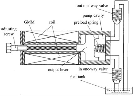
Fig. 1 depicts a typical GMP structure created by Chinese researcher Wang Chuanli from Anhui University of Technology [9]. A specific magnetic field will be produced inside the coil when current is applied. The GMM rod will produce magnetostriction as a result of the magnetic field's effects, driving the output rod and piston assembly to produce displacement and force, thus achieving the conversion of electromagnetic energy to mechanical energy. The mechanical energy will eventually be transformed into the kinetic energy of the liquid medium by the one-way valve's rectification action.
Fig. 1Structure diagram of high-frequency giant magnetostrictive pump
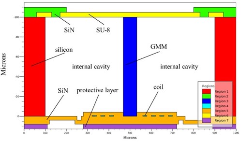
Based on the combination of conventional GMP structure with MEMS technology, a MEMS-GMP structure applicable to microfluidic systems is designed, and shown in Fig. 2.
Fig. 2Structure diagram of MEMS giant magnetostrictive micro-pump based on 0.18 μm integrated technology
The calculation formula for magnetic field strength is as follows:
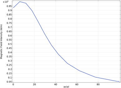
where is the number of coil turns, is the excitation current, is the effective magnetic circuit length. Establishing an electromagnetic field coupling physical model in COMSOL Multiphysics, through some calculations and simulations, we know that there is a relatively good axial and radial distribution ofmagnetic field intensity when the number of coil turns 15, the number of coil layers 5, the width of single wire 1.5 μm, the height of wire 0.8 μm, and the wire spacing 1.5 μm. At this time, the entire GMM rod can practicallywork in the saturation zone. Fig. 3 shows the magnetic field intensity distribution of the central axis of the GMM rod under this condition. Moreover, the current in each layer of coil 1 A.
Fig. 3The magnetic field intensity distribution of the central axis of the GMM rodunder the condition of five-layer coil, the magnetic field intensty reaches the maximum at the third coil
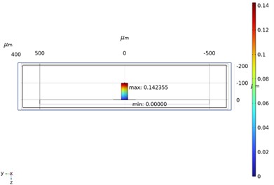
We designed the GMM rod with a length of 100 μm and a radius of 20 μm in this magnetic field to ensure that it operates normally. The displacement of the complete GMM rod as determined by simulation calculation is displayed in the left portion of Fig. 4 after creating a magnetostrictive physical model in COMSOL Multiphysics. The saturation magnetostrictive coefficient of the GMM is 1500 ppm. The highest theoretical elongation of the GMM is 0.15 μm, whereas the actual elongation is 0.142355 μm, and the rate of elongation is 94.9 %.
Fig. 4a) Side view of GMM rod central axis displacement, the top displacement reaches the maximum value; b) deformation distribution of SU-8 film in the working area
a)
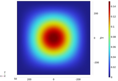
b)
The GMM rod's extension results in the deformation of the SU-8 elastic membrane. The right portion of Fig. 4 depicts the distribution of deformation in the SU-8 film’s working region. The shape of the membrane determines how much the internal cavity of the complete MEMS-GMP changes in volume. The actual volume change of a single operation is 1.2977×10⁻⁵ μL determined by integrating the displacement of the entire membrane.
After that, the one-way valve is modeled to enable the flow analysis. Assuming that the liquid sample is an ideal fluid, the flow formula at the check valve can be calculated using the Bernoulli equation as follows:
where, is the flow coefficient, is the valve disc length, is the Young’s modulus of valve disc material, is the valve disc thickness, is the atmospheric pressure, is the pump internal pressure, is the liquid density.
Establish a fluid-solid coupling physical model of the device in COMSOL Multiphysics and incorporate the above flow calculation formula, after calculation, the liquid can be completely sucked in or discharged (the variable volume part) within 1.82 μs, so the operating frequency of the system is set to 5×10⁴ Hz .
3. Materials and fabrication process
3.1. Smart Magnetic Materials
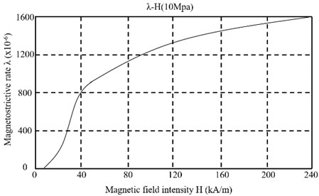
The phenomenon that ferromagnets produce shape changes such as length and volume under the action of external magnetic field is called magnetostrictive effect, the magnetostrictive coefficient of early materials is only on the order of 10-6-10-5, which is comparable to the thermal expansion coefficient [10-11]. Among the magnetostrictive materials, TbDyFe and Terfenol-D have been widely investigated due to their high magnetostriction coefficient and energy density, respectively. In recent years, NiMnGa has emerged as a novel magnetostrictive material exhibiting a magnetic shape memory effect, allowing it to alter its shape or size in response to a magnetic field. Its unique properties make it a potential candidate for various applications, particularly in the development of medical implants and microfluidic devices.
Fig. 5The relationship between magnetostrictive rate and magnetic field intensity of Terfenol-D, which is supplied by Tianxing Rare Earth Company, China
4. Fabrication process
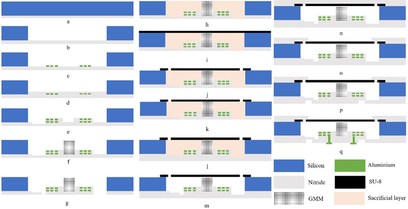
Fig. 6 is a schematic diagram of the whole manufacturing process. a) Choose a silicon wafer with the thickness of 100 μm, and use LPCVD to develop a layer of silicon nitride with the thickness of 4 μm after surface cleaning; b) Use as an etching gas, as an bombarding ion, etching the silicon on the back by ion-assisted plasma etching; c) Evaporated aluminum coil; d) Grow a silicon nitride passivation layer by LPCVD; e) Repeat steps c and d numerous times to manufacture multilayer coils and plasma etch silicon nitride; f) GMM rod manufactured by LIGA process; g) Plasma etching removes silicon nitride; h) Deposite sacrificial layer material, and then flatten the surface; i) Spincoat polymer materials; j) Expose and develop the photoresist; k) A metal anti-bonding layer is evaporated on the back; l) A layer of 4 μm thick silicon nitride is produced by LPCVD; m) Release sacrificial layer; n) Silicon nitride is grown by LPCVD; o) Etch front silicon nitride by plasma etching; p) Etch back silicon nitride by plasma etching; q) Through hole is etched by plasma etching and aluminum electrode is evaporated.
Fig. 6The complete manufacturing process of the MEMS giant magnetostrictive pump, some parts include multiple processes
5. Operation process analysis
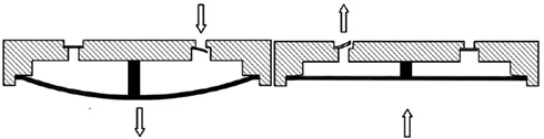
There are two phases to the MEMS pump’s operation. The suction phase is the first phase. The valve plate of the inlet valve opens, the valve plate of the outlet valve shuts, the film is deformed outward, the volume of the pump cavity grows, the pressure in the cavity lowers, and liquid enters the pump cavity through the intake valve’s valve port; The second phase is the discharge phase. When the film returns to its original position, the pressure in the cavity increases, the valve plate of the outlet valve opens, the valve plate of the inlet valve closes, and the fluid is discharged from the pump cavity from the valve port of the outlet valve, thus a complete flow cycle is accomplished. Fig. 7 shows the schematic diagram of two phases.
Fig. 7Schematic diagram of the position of membrane, GMM rod and check valve at different operation phases
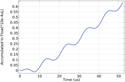
The actual accumulated flow of the inlet valve is determined and displayed in Fig. 8 based on the simulation model developed in CMOSOL in the preceding text. We have observed a phenomenon known as liquid reverse discharge that occurs just before the inlet valve closes. Similar to this, liquid reverse suction occurs just before the outlet valve closes. This occurrence occurs because the two valves need some time to return, which prevents them from doing so instantly. This time cannot be disregarded, even if it is less than the time needed for opening.
Fig. 8The curve of the actual accumulated in flow, the curve is rising as a whole, while when the maximum value is reached, there is a phenomenon of backflow
6. Conclusions
In conclusion, this paper has presented a new micro-pump structure that utilizes magnetic smart materials, which have the ability to sense changes in the environment and respond accordingly. The proposed micro-pump design has been optimized for enhanced performance and efficiency, with one-way valves incorporated into the structure. The manufacturing process and material characteristics of the micro-pump have been discussed, and simulation results have demonstrated improved performance compared to conventional designs.
This study highlights the potential of magnetic smart material-based micro-pumps in various fields, including biomedical engineering and lab-on-a-chip devices. Further research is required to explore the potential applications of this technology and to optimize its performance further. Overall, the findings of this study contribute to the ongoing efforts to develop innovative micro-pump designs that utilize smart materials to enhance performance and efficiency in fluidic systems.
References
-
R. Walczak, “Lab-on-a-chip fluorescence detection with image sensor and software-based image conditioning,” Bulletin of the Polish Academy of Sciences Technical Sciences, Vol. 59, No. 2, 2011.
-
M. G. Pollack, R. B. Fair, and A. D. Shenderov, “Electrowetting-based actuation of liquid droplets for microfluidic applications,” Applied Physics Letters, Vol. 77, No. 11, pp. 1725–1726, Sep. 2000, https://doi.org/10.1063/1.1308534
-
J. Lee, H. Moon J. Fowler, C.-J. Kim, and T. Schoellhammer, “Addressable micro liquid handling by electric control of surface tension,” in 14th IEEE International Conference on Micro Electro Mechanical Systems, pp. 499–502, 2001, https://doi.org/10.1109/memsys.2001.906588
-
S. K. Cho, S. K. Fan, H. Moon, and C. J. Kim, “Toward digital microfluidic circuits: Creating, transporting, cutting and merging liquid droplets by electrowetting-based actuation,” in 15th IEEE International Conference on Micro Electro Mechanical Systems, pp. 11454–11461, 2002, https://doi.org/10.1109/memsys.2002.984073
-
P. R. C. Gascoyne and J. V. Vykoukal, “Dielectrophoresis-based sample handling in general-purpose programmable diagnostic instruments,” Proceedings of the IEEE, Vol. 92, No. 1, pp. 22–42, Jan. 2004, https://doi.org/10.1109/jproc.2003.820535
-
A. A. Darhuber, J. P. Valentino, S. M. Troian, and S. Wagner, “Thermocapillary actuation of droplets on chemically patterned surfaces by programmable microheater arrays,” Journal of Microelectromechanical Systems, Vol. 12, No. 6, pp. 873–879, Dec. 2003, https://doi.org/10.1109/jmems.2003.820267
-
A. Renaudin, P. Tabourier, V. Zhang, C. Druon, and J.-C. Camart, “Plateforme SAW dédiée à la microfluidique discrète pour applications biologiques,” La Houille Blanche, Vol. 92, No. 3, pp. 26–30, May 2006, https://doi.org/10.1051/lhb:200603003
-
C. Chu, R. Zhu, X. Jia, and X. Zhang, “Design and analysis of giant magnetostrictive actuator,” in 2022 IEEE International Conference on Advances in Electrical Engineering and Computer Applications (AEECA), pp. 827–832, Aug. 2022, https://doi.org/10.1109/aeeca55500.2022.9918877
-
C. Wang, X. Cheng, and P. An, “Performance analysis of GMM high frequency micro pump,” (in Chinese), Hydraulic and Pneumatic, Vol. 9, pp. 70–73, 2010.
-
A. R. Smith, A. Saren, J. Järvinen, and K. Ullakko, “Characterization of a high-resolution solid-state micropump that can be integrated into microfluidic systems,” Microfluidics and Nanofluidics, Vol. 18, No. 5-6, pp. 1255–1263, May 2015, https://doi.org/10.1007/s10404-014-1524-6
-
I. Kulagin, M. Li, V. Laitinen, and H. Handroos, “Review of MSM actuators: applications, challenges, and potential,” IEEE Access, Vol. 10, pp. 83841–83850, 2022, https://doi.org/10.1109/access.2022.3197278
About this article

This work was supported by Key Special Projects of National Key R&D Plan: 2019YFB2204601.
The datasets generated during and/or analyzed during the current study are available from the corresponding author on reasonable request.
The authors declare that they have no conflict of interest.
