Abstract
Under certain circumstances, the Alford force might induce instability of the rotor system. The mechanism and influence factors of the Alford force induced instability were analyzed with the Jeffcott rotor. Then a method for calculating the instability threshold was proposed. Finally, the optimization model of a high-speed micro-turbojet engine was established to optimize the instability threshold. The results show that the anisotropy of support stiffness and the damping ratio can both improve the threshold of instability. The instability threshold can be greatly improved by optimizing bearing stiffness and diameter of the rotor system.
Highlights
- Anisotropy of the support stiffness can improve the instability threshold of the system.
- The calculation method for instability threshold is proposed.
- An optimization model is established to improve the system instability threshold.
1. Introduction
With the development of modern science and technology, the speed and performance of aero-engines have been continuously improved, so that the rotors are mostly designed with flexible structures, and the operating speed often exceeds the first-order or even the second-order critical speed. The increase of the rotor speed leads to an increase in the aerodynamic load which resulting in more severe airflow excitation.
The airflow excitation caused by the eccentricity of the impeller has drawn much more attention in recent years. In 1958, Thomas H. J. [1] first proposed the problem of airflow excitation caused by the eccentric rotor of the impeller when studying the vibration of the steam turbine. In 1964, Alford J. S. [2] also raised a similar problem when studying the vibration of aviation gas turbine engine, and derived a widely cited formula. Therefore, the airflow excitation force caused by the eccentricity of the impeller is also called the Alford force. In 1984, Vance J. M. [3] confirmed the existence of Alford force with a blower. Ehrich F. [4] gave the expression of the efficiency coefficient in the Alford force formula. Wang J. H. [5] carried out the optimal design of the rotor structure considering the Alford force. Kim [6] established a fluid-structure interaction model to study the effect of Alford force. Yan Litang [7] conducted theoretical and experimental research to study the influence of the Alford force on the compressor rotor. Both numerical and experimental results showed that the Alford force would cause backward whirl. Chai Shan [8] deduced the formula for calculating the excitation force of the air flow in the gap of the steam turbine blade from the perspective of fluid mechanics. In 2014, Yue Ertuan [9] studied the influence of air gap eccentricity on the vibration characteristics of the permanent magnet motor rotor system. Weng Lei [10-11] studied the dynamic characteristics of cracked rotor-bearing rotor system considering the Alford force and the nonlinear force of the oil film. In 2020, Li Bin [12] established a dynamic model to study the vibration characteristics of the system with nonlinear Alford force and blade-bending vibration. The influence of airflow excitation caused by impeller eccentricity on rotor characteristics has become one of the most important research directions in rotor dynamics.
In this paper, the influence of Alford force on the stability of the rotor system is analyzed. Then a calculation method for the instability threshold is proposed. Finally, the stability of a high-speed rotor system is improved by optimizing the structural parameters.
2. Mechanism of instability
Due to manufacturing error and unbalanced force, relative eccentricity will occur between the rotor and the stator, so that the blade tip clearance is unevenly distributed along the circumference, resulting in unequal aerodynamic force on each blade. Therefore, in addition to a torque, the circumferential aerodynamic force of the blade also synthesizes a lateral force acting on the rotor, that is, the Alford force. Generally, it can be expressed as:
where, is the torque acting on the blade; is the middle diameter of the blade; is the height of the blade; is the eccentricity; is the efficiency coefficient of the exciting force.
Assume that the displacement is linearly dependent on the excitation force:
The blade of the turbine with higher efficiency does more work, thus bearing more aerodynamic load. The resultant force would push the rotor to precess forwardly. Then, the Alford force for the turbine rotor can be expressed as:
Experiments have shown that when the inlet pressure of the compressor rotor is uniform, the outlet pressure is roughly sinusoidal, and the maximum pressure point would exceed the minimum clearance position of the blade tip by 60° [13]. So the exciting force of the airflow would cause the compressor rotor to precess backwardly. At this time, the Alford force can be expressed as:
From Eq. (3) and Eq. (4), it can be seen that it is equivalent to adding a cross stiffness term to the equation of motion of the rotor system.
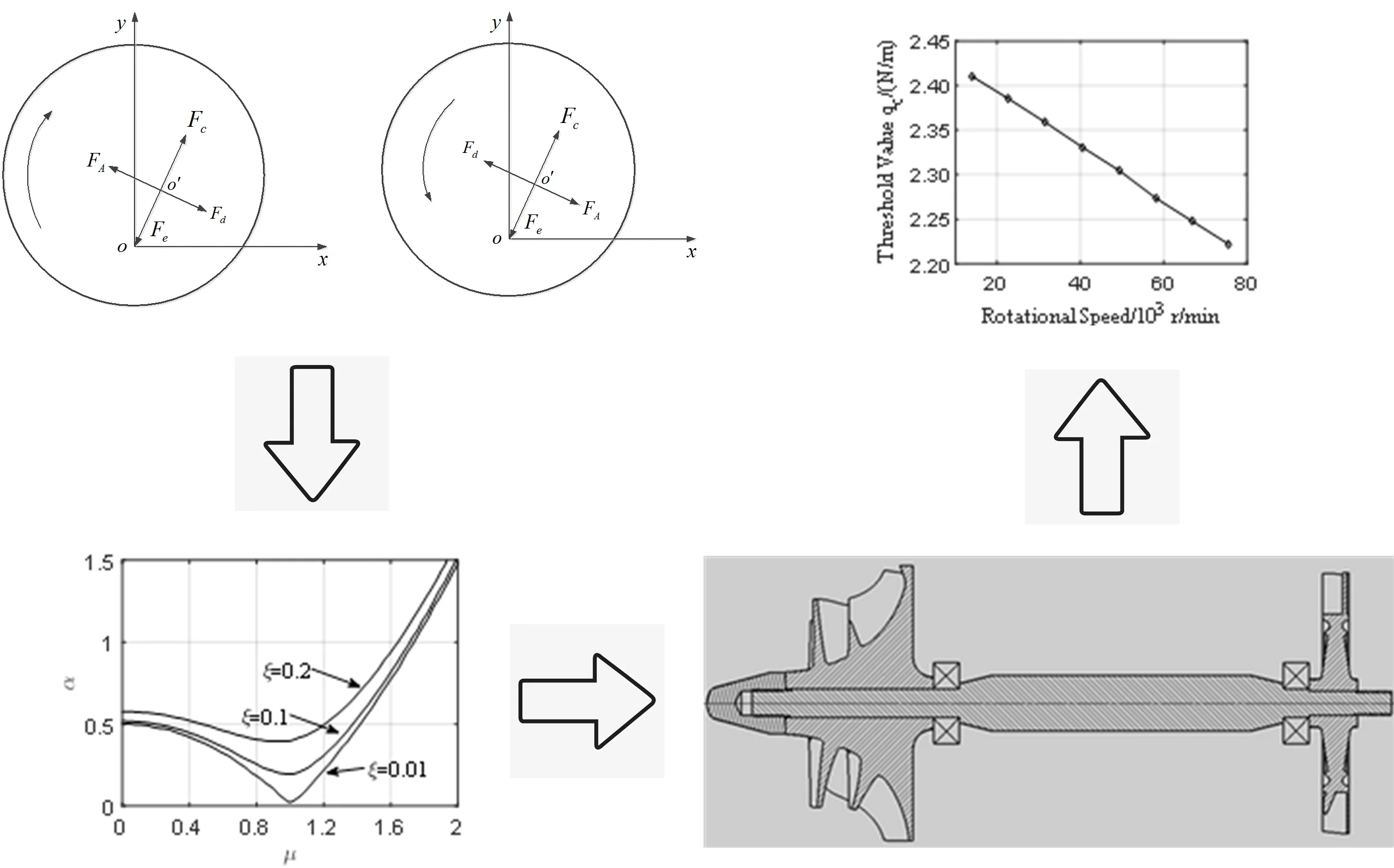
The mechanism of instability caused by the cross stiffness is illustrated in Fig. 1. Let point represent the axis of the rotor before deformation, and point represent the axis after deformation. Assuming that the rotor precesses due to initial disturbance, the direction of the precession is shown by the arrow in Fig. 1. The disk is subjected to the inertial force , the elastic restoring force , the external damping force , and the excitation force generated by the cross stiffness. If the exciting force is greater than the external damping force , the precession would be accelerated, which would lead to further increasing of the inertial force, the deflection and the exciting force. In this way, the vibration amplitude of the precession increases continuously until it is limited by the structure or destroyed.
3. Influence factors of instability
The Jeffcott rotor shown in Fig. 2 is introduced to study the influence of Alford force on stability.
Fig. 1Schematic diagram of rotor instability
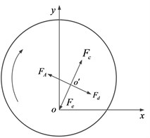
a) Forward whirl
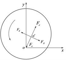
b) Backward whirl
Fig. 2The schematic diagram of the Jeffcott rotor
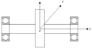
The equation of motion of the rotor system is:
The stiffness matrix of the system consists of the stiffness of the supports and the cross stiffness caused by the Alford force.
Taking the turbine rotor as an example, the influence of Alford force on the rotor system is analyzed. Neglecting the influence of support cross stiffness and cross damping, Eq. (5) can be expressed as:
Let and :
Let , , , , , , and non-dimensionalize the Alford force . Substituting into Eq. (8) to obtain:
In which: , , , , .
The stability of the system can be determined by the Routh-Hurwitz (R-H) criterion. The Hurwitz matrix is established as:
According to the (R-H) criterion, the condition to maintain stable [13]:
Substituting ~ into Eq. (11):
For the compressor rotor, the equation of motion of the system is:
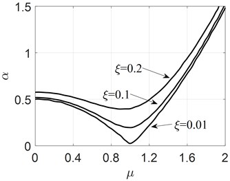
After similar derivation, the exact same inequality as Eq. (12) can be obtained. Fig. 3 can be obtained by solving Eq. (12). From Fig. 3, it can be seen that: (1) when (i.e. ), the system has the smallest , so is , indicating that the asymmetry of the support stiffness can improve the threshold value of the system stability; (2) increases with the damping coefficient , indicating that damping also can improve the threshold value of system stability. Therefore, the Alford force may cause rotor instability, and the threshold value of the stability of the rotor system can be improved by increasing the asymmetry of the bearing stiffness and increasing the damping.
Fig. 3The influence of support stiffness on stability
4. Threshold optimization
4.1. Determine the threshold value
After considering the influence of Alford force, the motion equation of the rotor system can be expressed as:
In which, , and are the inertia matrix, damping matrix and stiffness matrix, respectively; is the gyroscopic matrix; is the cross-stiffness matrix introduced by the Alford force; is the unbalanced force vector.
Introducing :
In which:
The eigenvalues of Eq. (15) can be expressed as:
where, – damping factor; – natural frequency.
According to the stability criterion, the system is stable if and only if the real part is negative. Therefore, at a certain rotational speed, taking different values of and substituting into Eq. (15) to obtain . When one of them is zero, the corresponding value of is the instability threshold value at that speed. In the same way, the corresponding instability threshold speed under a certain can also be calculated.
4.2. Optimization
In order to reduce the influence of Alford force on the system, the relevant parameters of the high speed micro-turbojet engine are optimized, Fig. 4. The compressor impeller adopts aluminum alloy and nickel-based superalloy is adopted for the turbine. Corresponding material properties are listed in Table 1. Maximum operating speed of the rotor is 80000 r/min.
Fig. 4The high speed rotor of a micro-turbojet engine
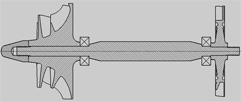
Table 1Material property
Young’s modulus (GPa) | Poisson ratio | Density (Kg/m3) | |
Impeller | 70 | 0.346 | 2710 |
Turbine and shaft | 214 | 0.310 | 8880 |
Analysis in previous section reviewed that the support stiffness would affect the instability threshold of the system. Also, the shaft diameter may change stiffness distribution of the rotor system so as the instability threshold. Therefore, the optimization problems under two different conditions were formulated. For the first case, only support stiffness were chosen as the design variables, Eq. (17) and Eq. (18). Then the support stiffness remains constant and the shaft diameters were changed to maximize the objective function, Eq. (17) and Eq. (19). The objective function and constraints were listed in Eq. (17)-Eq. (19):
Subject to:
or:
In Eq. (18): and are the support stiffness of the th bearing; 2×10⁶ N/m and 2×10⁸ N/m are the lower and upper limit of the corresponding support stiffness respectively.
In Eq. (19): is the diameter of the ith shaft segment; 8 mm and 16 mm are the lower and upper limit of the diameter of the th shaft segment, respectively. Due to structural limitation, only the shaft segment between the two bearings was optimized.
In this paper, the genetic algorithm with adaptive global search is used as the optimization method.
4.3. Results
The inertia matrix, damping matrix, gyrscopic matrix and stiffness matrix of the rotor system shown in Fig. 4 are established with Timoshenko beam theory [14]. At the same time, the effect of the cross stiffness caused by the Alford force at the impeller and the turbine are considered.
The instability threshold of the rotor system at different speeds is analyzed and the results are shown in Fig. 5. It can be seen that the instability threshold decreases with rotational speed increasing. On the other hand, it can be known from Eq. (2) that the Alford force increases with power or rotating speed of the rotor system. Therefore, special attention should be paid to the influence of Alford force when designing high-speed rotor systems, especially micro-turbojet engine with rotational speed up to 100,000 r/min.
In order to improve the instability threshold of the micro-turbojet engine, the support stiffness of the rotating shaft of the system were optimized. Using Eq. (17) and Eq. (18), the optimum bearing stiffness corresponding to the maximum can be obtained. The results were compared with the original plan and the Anisotropic Limit plan, see in Table 2. It can be seen that the anisotropic support can greatly improve the instability threshold of the rotor system and there is an optimal support stiffness value to maximize the instability threshold.
The second optimization was carried out with the shaft diameter as the design variable and considering Constraint No. 2. Using Eq. (17) and Eq. (19), the diameter corresponding to the maximum was found to be 16 mm, which is compared with the original diameter, as shown in Table 3. It can be seen that the optimal value is just at the upper limit, indicating that increasing the diameter of the shaft segment between the two bearings as much as possible can improve the instability threshold of the rotor system.
Fig. 5The influence of rotational speed on instability threshold
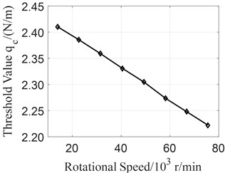
Table 2Optimization results comparison – support stiffness
Original | Anisotropic limit | Optimized value | |
/ (N/m) | 2.00×10⁷ | 2.00×10⁶ | 3.58×10⁶ |
/ (N/m) | 2.00×10⁷ | 2.00×10⁸ | 1.95×10⁸ |
/ (N/m) | 2.25×10⁵ | 1.45×10⁶ | 1.65×10⁶ |
Table 3Optimization results comparison – shaft diameter
Original | Optimized value | |
/ (mm) | 10 | 16 |
/ (N/m) | 2.25×10⁵ | 3.27×10⁶ |
5. Conclusions
The mechanism of instability caused by impeller eccentricity is analyzed and the stability is determined by the Routh-Hurwitz criterion. The analysis shows that the anisotropy of the support stiffness and the increase of the damping ratio can improve the threshold value of the system. The calculation method for instability threshold is proposed. An optimization model is established to improve the system instability threshold by optimizing the support stiffness and the diameter of the rotating shaft. The results show that the optimization can greatly improve the instability threshold of the high-speed micro-turbojet engine.
References
-
H. J. Thomas, “Unstable natural vibration of turbine rotors induced by the clearance flow in glands and blading,” Bulletin of the AMS, Vol. 71, No. 11, pp. 1039–1063, 1958.
-
J. Alford, “Protecting turbomachinery from self-excited rotor whirl,” Journal of Engineering for Power, Vol. 87, No. 5, pp. 333–344, 1965.
-
J. M. Vance and F. J. Laudadio, “Experimental measurement of Alford’s force in axial flow turbomachinery,” Journal of Engineering for Gas Turbines and Power, Vol. 106, No. 3, pp. 585–590, Jul. 1984, https://doi.org/10.1115/1.3239610
-
F. Ehrich, “Rotor whirl forces induced by the tip clearance effect in axial flow compressors,” Journal of Vibration and Acoustics, Vol. 115, No. 4, pp. 509–515, Oct. 1993, https://doi.org/10.1115/1.2930379
-
J. H. Wang and F. M. Shih, “Improve the stability of rotor subjected to fluid leakage by optimum diameters design,” Journal of Vibration and Acoustics, Vol. 112, No. 1, pp. 59–64, Jan. 1990, https://doi.org/10.1115/1.2930099
-
Kim H. S., Cho M. H., and Song S. J., “Stability analysis of a turbine rotor system with Alford forces,” Journal of Sound and Vibration, Vol. 258, No. 4, pp. 777–790, 2002.
-
Yan L. T. et al., “Analysis the self-exciting force and stability caused by blade tip clearance of the compressor,” (in Chinese), Journal of Aerospace Power, Vol. 9, No. 2, pp. 157–160, 1994.
-
Chai S. et al., “An analysis on the air exciting-vibration force caused by clearance,” (in Chinese), Chinese Journal of Mechanical Engineering, Vol. 36, No. 4, pp. 34–37, 2000.
-
Yue Ertuan, Gan Chunbiao, and Yang Shixi, “Vibration characteristics analysis of a rotor for a permanent magent motor with airgap eccentricity,” (in Chinese), Journal of Sound and Vibration, Vol. 33, No. 8, pp. 29–34, 2014.
-
Weng Lei, Yang Zichun, and Cao Yueyun, “Bifurcation characteristic of rotor-bearing system under air-exciting forces of steam turbine,” (in Chinese), Journal of Naval University of Engineering, Vol. 27, No. 5, pp. 52–57, 2015.
-
Weng Lei, Yang Zichun, and Cao Yueyun, “Bifurcation characteristic of a cracked rotor-bearing system under air-exciting forces of steam turbine,” (in Chinese), Journal of Sound and Vibration, Vol. 35, No. 5, pp. 89–95, 2016.
-
Li Bin, Zhang Lei, and Cao Yue-Yun, “Dynamic characteristic analysis for rotor-bearing system with Alford force considering blade vibration,” (in Chinese), Journal of Ship Mechanics, Vol. 24, No. 1, pp. 98–107, 2020.
-
Yang L. T., Zhu Z. G., and Li Q. H., The Vibration of High Speed Rotating Machines. Beijing, China: National Defense Industry Press, 1994.
-
F. Wang, G.-H. Luo, X.-G. Yang, and H.-T. Cui, “Research on modeling and dynamic characteristics of complex coaxial rotor system,” Journal of Vibroengineering, Vol. 19, No. 3, pp. 1524–1545, May 2017, https://doi.org/10.21595/jve.2016.17324
About this article

Funding from the Aero Science Foundation of China (Grant No. 201928056001) is gratefully acknowledged. Funding from Project 1912 is gratefully acknowledged.
