Abstract
In view of the fact that integrated intelligent tower construction machine which is designed to improve the construction efficiency and quality and operating conditions of bridge towers always withstand various wind loads (especially super typhoons or gusts) so that hidden dangers may exist in their structural safety and reliability, their structural dynamic characteristics analysis of effects of strong winds shall be an essential part in their design stage. For this purpose, Davenport wind speed spectra were used to simulate the extreme pulsating wind loads and their structural dynamic wind-induced responses were investigated by means of the finite element method (FEM) to gain the displacement and stress responses of key nodes and then determine their structural design safety. The results show that: the maximum stress and displacement occur in the upper parts of their frames; and the forces and displacement of their structural dangerous positions are within their corresponding safe ranges. Our analysis results can provide a theoretical reference for application and structural optimization of tower machine.
1. Introduction
Concrete bridge towers taking advantages such as the high rigidity and good stability become important structures supporting cable bridges. With rapid development of the transportation industry, popularity of large spans and novelties of modern bridges, the cross-section and height of bridge towers increase accordingly so that those requirements for the construction accuracy and safety measures shall be higher. Researches are focusing on how to ensure the construction quality, ergonomics and safety of bridge towers.
In earlier times, those construction methods such as the slip-form method were primarily applied for concrete bridge towers, for which supporting rods preset inside poured concrete structures were utilized to move upwards the work platform and templates by means of the lifting system and achieve continuous concreting [1]. Such method results in high construction efficiency but its workload is large and lateral cracks and slips cannot be avoided on the construction surfaces; moreover, it is difficult to guarantee the construction accuracy for any bridge tower with a large slope and complicated structures. In addition, concrete parts and so on are lifted and slip forms are disassembled with the help of lifting equipment; and slipping height of forms is also restricted to a certain degree. For that reason, the hydraulic climbing formwork method is becoming popular for construction of high-rise concrete structures in recent years due to its advantages such as high construction quality and safety as well as strong applicability [2], for which the climbing frame and formworks are lifted with the help of its own hydraulic lifting system with a safe and reliable power system; and the frame structures can be flexibly arranged; rather, it has disadvantages such as poor integrity, small loading capacity, high sensitivity to weather and difficultly setting up its material displacement and maintenance system. At present, most concrete bridge tower construction methods have certain limitations and industrialization of construction technologies remains a low level. For example, those existing issues such as low positioning accuracy of steel bars, low acceptability of protective layers and poor concrete curing conditions are difficult to adapt to the modern bridge construction trends.
The development of bridge intelligent construction technologies are of great significance for improving the quality of bridges, enhancing safety guarantees and promoting environmental protection and is becoming an effective way to solve the shortage of traditional construction [3]. Thus, a kind of intelligent tower machine integrating concrete displacement and curing functions was out forward here to overcome the issues of traditional construction equipment, greatly improve the working environment of workers, reduce the needs of workers, improve the construction efficiency and product quality and guarantee construction safety. An FEA model was established to determine the load strength of the tower machine structures under effects of strong winds and analysis was performed to their pulsating wind-induced responses. Our study may provide a theoretical reference for engineering applications of tower machine.
2. Structural characteristics of integrated intelligent tower construction machine
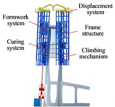
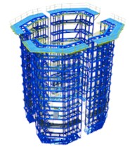
An integrated intelligent tower construction machine (Fig. 1(a)) is mainly made up of a climbing mechanism, a curing system, a frame structure, a formwork system, a displacement system and other structures. Its overall structure is mainly composed of 4 sets of frames directly supporting its 8-layeroperation runway system (Fig. 1(b)). Frames primarily include the concreting, curing and rehabilitation layers. 4 sets of frames are connected by tie rods. The total height of the entire structure is 26.7 m.
Fig. 1Integrated intelligent tower construction machine
a) Entire structure
b) Frame structure
c) Climbing mechanism
d) Displacement system
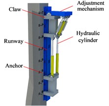
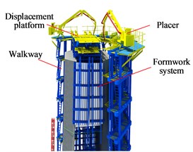
The climbing mechanism as a key loading part of the tower crane with a great loading capacity is primarily to connect and displace the machine and the bridge tower, which is structurally shown in Fig. 1(c) and operated by its hydraulic control system with a overvoltage protection unit. The frame includes main load-bearing frameworks on both sides of its climbing mechanism; and its top displacers are laterally connected to its runway to counterbalance any frame unbalanced load. The displacement system is primarily made up of 2 displacers and a displacement platform which is arranged on the top of the inner formwork and also acts as a covering platform against newly poured concrete being exposed to the sun and rain except for an operation runway for displacement personnel. There is a gap (1.35 m) between the frame structure and the tower body primarily for removal of frameworks and switching of runways. The curing consists of a closed enclosure curtain system and a thermal fog curing system; the former is made of fireproof and heat-insulating materials and designed as segmented and dewing storage schemes while the latter includes a thermal fog generating device for adjustment of temperature and humidity, thermal fog homogenization and guide pipeline. Thermal fog effectively guarantees the concrete curing quality. Additionally, the inner and outer framework panels are made of composite steel plates. The outer frameworks can climb upwards against the frame structure while the inner frameworks attached their inner frame may be lifted up by the tower construction machine. The inner and outer frameworks include reference and change blocks. The change block frameworks are generally matched across the entire bridge to avoid cutting frameworks and ensure the quality of concrete construction.
3. Determination of wind loads
Wind loads is one of main considerations for the structural design of high-rise buildings [4]. For investigation of effects of wind loads on the tower construction machine structures, it is assumed that wind is loading perpendicularly the machine structures. Wind loads generally include long-period average wind and short-period pulsating wind. By taking the actual situation into account, (the wind speed) at time (), which is equivalent to superposition of (average wind speed) and (pulsating wind speed), is expressed as:
Due to its long vibration period, the direction of other physical quantities are usually regarded as independence on time. Considering the irregularity of wind, the intensity of is random and becomes crucial to induce structural vibration. In engineering, Davenport pulsating wind speed spectra are usually utilized to perform its simulation [5], whose density function is defined as:
where: represents the ground roughness coefficient; represents the average wind speed at the position 10 m away from the workplace; represents the turbulent integral scale coefficient, which is calculated by means of ; and represents the pulsating wind frequency.
As for simulation of wind loads, the harmonic superposition method is based on the triangular series summation and a random process is applied to ensure that discrete spectra can approximate the target spectra; thus, the calculation speed is fast and the applicability is extensive. Especially, simulation based on Shinozuka’s harmonic superposition method leads to the high accuracy of [6], whose theoretical pulsating wind speed is expressed as:
where: represents the division number of the wind spectral frequency range, which shall be an enough large positive integer; represents the increment of the wind spectral frequency; represents the lower triangular matrix, which is solved by means of the Cholesky decomposition of the cross power spectral density function matrix for the wind spectra; and represents a uniformly distributed random variable in the interval of (0, 2).
According to Eq. (1), the wind load () is expressed as:
where: represents the average wind load; and represents the pulsating wind load.
Wind loads of a structure is closely related to its windward area and wind speed. can generally be expressed as:
where: represents the wind pressure change coefficient; represents the windward area of the structure; represents the wind power coefficient; and represents the calculated wind pressure, which is related to the air density () and the calculated wind speed () and can be solved by means of .
is calculated by:
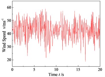
The conditions for analysis of our tower construction machine were determined based on the once-in-a-century wind speed for a certain area. Its is 43 m/s. calculated based on the Matlab simulation is shown in Fig. 2. The wind speed of 43 m/s is the maximum value of the measured data in the region in the past 100 years. At the same time, the wind speed in the construction area has been monitored on the spot in recent 2 years, and the wind speed is less than this value.
Fig. 2v(t) vs. time (v-10= 43 m/s)
4. Structural dynamic FEA
4.1. FEM-based modeling
For analysis of wind-induced dynamic responses of the tower construction machine and in accordance with its structural characteristics, ANSYS modeling was performed to 1/2 of its frame to improve the calculation efficiency. As for material properties, various structures are assumed to be Q345 (elastic modulus: 2.06× 10⁵ MPa; Poisson’s ratio: 0.3; and density: 7.8×10³ kg/m3). The degree of densification of grids of each truss is appropriately controlled for meshing [7]. The truss structure adopts BEAM188 units. The contact between the frame anti-overturn roller and each runway adopt contact units. The meshing map is shown in Fig. 3.
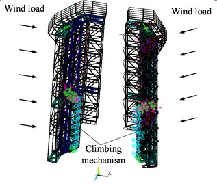
Setting rational boundary conditions for the FEA model of the tower crane shall be crucial for the accuracy of its dynamic response solution [8]. The crane moves or stops by means of its climbing mechanism. The climbing runways are anchored to the side walls of poured concrete tower. Thus, the motion degrees of freedom in Directions , and shall be restricted at anchors of each runway, respectively (Fig. 4). Moreover, the gravity acceleration is applied to the entire machine structure. Also, wind loads of those structural parts such as the displacer, machine and pumping station which are regarded as mass points are applied to their corresponding nodes.
Fig. 3Meshing map of our machine frame
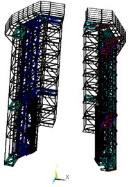
Fig. 4Setting of the boundary
4.2. Results and discussion
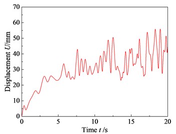
The wind-induced displacement cloud diagram of the machine frame is shown in Fig. 5 which indicates that the displacement falls with the growth of the distance to the top of themachine and the maximum displacement may be up to 56.28 mm. The corresponding displacement-time curve is shown in Fig. 6 which shows that the wind-induced displacement initially rises on the whole and it is stable in a certain range after a period of time. It can be known in accordance with Code for Design of Steel Structures (GB 50017-2003) [9] that the column top displacement of a multi-layer frame is no more than /300 (/300 = 26700/300 = 89 mm; : the total height of the steel structure frame). Thus, the structural deformation of the machine is within the safe range under the extreme wind load.
Fig. 5Displacement cloud diagram of the machine frame
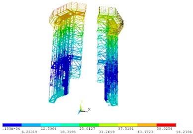
Fig. 6Node displacement response
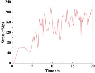
The stress cloud diagram (Fig. 7) of the machine frame indicates that stresses of those locations of those parts such as the displacer and crane are larger. The maximum stress () is up to 211.61 MPa and the corresponding stress-time relation is shown in Fig. 8 which shows that the stress is similarly stable within a certain range after a period of time. Its allowable safety factor () ranges from 1.2 to 1.5 in accordance with Safety Factor and Allowable Stress of Steel Structures [10]. The yield strength () of Q345 is known to be 345 MPa. Then, . Thus, the force is within the safe range at the dangerous position of the machine frame.
Fig. 7Stress cloud diagram of the machine frame
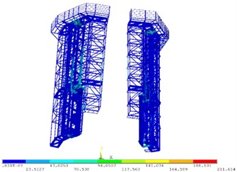
Fig. 8Time history response curve of the maximum stress point
5. Conclusions
An kind of Integrated intelligent tower construction machine was put forward to overcome those issues such as the low efficiency and poor construction quality of traditional construction technologies. The machine frame structure was studied and FEA was performed to its wind-induced displacement and stress responses under the extreme pulsating wind loads to determine the locations with the maximum structural displacement and stress and judge its structural design stability. A theoretical basis may be provided for the engineering applications and structural design of such tower construction machine. With the bridge towers and buildings getting higher and higher, the test of wind on construction equipment is very severe. How to effectively ensure the safety of construction equipment and reduce the self weight of the structure is a complex subject. The research results can provide some reference for solving the above problems.
References
-
J. D. Yin, “Design and construction of hydraulic climbing formwork for hollow high bridge piers,” (in Chinese), Urban Roads Bridges and Flood Control, Vol. 2, pp. 38–42, 1994, https://doi.org/10.16799/j.cnki.csdqyfh.1994.02.006
-
X. Z. Ji, B. T. Jia, J. Guo, and Z. H. Liu, “Construction technical control of tower columns of cable tower of Qingshuihe River Railway Bridge,” (in Chinese), Highway, Vol. 60, No. 10, pp. 118–121, 2015.
-
Y. M. Zhu, “Development status and trends of road and bridge construction technologies,” (in Chinese), Dwelling Residence, No. 30, 2017.
-
B. C. Hu, “Modeling of equivalent random static wind loads for high-rise buildings,” (in Chinese), Automation and Instrumentation, Vol. 12, pp. 198–201, 2018, https://doi.org/10.14016/j.cnki.1001-9227.2018.12.198
-
X. Xu, Y. Liu, and X. J. Zhou, “FEA on wind-induced responses of high-rise structure based on simulation of wind duration,” (in Chinese), Chinese Quarterly of Mechanics, Vol. 30, No. 2, pp. 304–310, 2009.
-
M. Shinozuka and G. Deodatis, “Simulation of Stochastic Processes by Spectral Representation,” Applied Mechanics Reviews, Vol. 44, No. 4, pp. 191–204, Apr. 1991, https://doi.org/10.1115/1.3119501
-
C. Singh and J. S. Saini, “Algorithms for accurate and fast plotting of contour surfaces in 3D using hexahedral elements,” Journal of The Institution of Engineers (India): Series C, Vol. 97, No. 3, pp. 389–405, Jul. 2016, https://doi.org/10.1007/s40032-016-0233-1
-
J. G. Nie, M. Zhou, T. G. Ji, J. S. Fan, Y. H. Wang, and H. B. Wang, “Study on behaviors of cable anchorage zone of self-anchored suspension bridges with steel box girders based on multi-scale modeling method,” (in Chinese), China Civil Engineering Journal, Vol. 47, No. 6, pp. 57–69, 2014, https://doi.org/10.15951/j.tmgcxb.2014.06.002
-
“GB 50017-2003. Code for Design of Steel Structures,” (in Chinese), China Planning Press, Beijing, 2003.
-
Xu H., Safety Factor and Allowable Stress. (in Chinese), Beijing: China Machine Press, 1981.
About this article

