Abstract
A machine-tool structure optimization is an important technique that improves the machining efficiency and saves materials and the energy resource. In this work, dynamic design optimization method for Machine-Motorized-Spindle (MMS) subjected to a number of rotating unbalanced forces effects is presented. Linear forced-Rotordynamic analysis with design explorer method has been used to simulate the output response. The Design Variables (DVs) and their limits were carefully chosen and applied to develop the Design-of-Experiment (DOE). The Box-Behnken Design (BBD) method, because of its good organization in providing much information in a minor number of required statistical experiments was used to generate the DOE. The influences of DVs on the dynamic of MMS and their levels optimization were evaluated by utilizing the Response-Surface (RS) method. The results showed that the spindle shaft inner diameter of the motor-rotor seat and its rotating unbalanced mass, and modulus of elasticity have the highest contribution in effect on the dynamic of MMHS. As well, it is found that the proposed optimization method not only improves the structural weight of MMS, but also the potential saving can be achieved in term material and energy resource.

Highlights
- Parametric Optimization problem
- Design of Experiment for design space exploration
- Response Surface model
- Check the quality of Response Surface model, Sensitivities analysis
- Optimization based on Response Surface model
1. Introduction
The machine-tool spindle has an important role in machining process, since it provides a relative movement among the tool and workpieces, and also, the torque required to remove material. In general, the rotating unbalance forces induced due to workpieces-holder and motor-rotor will subsequently cause the vibration of the spindle. Thus, the vibration behaviors of unbalance-response remain a foundation of a research for vibration observing and balancing-control [1]. Because of complex structures of MMS, the evaluation of dynamic-characteristics produced by rotating unbalance force is much difficult [2]. The vibration response caused by rotating-unbalance force induced on the spindle-system was widely investigated by considerable researches [3, 4]. Zhou et al. [5], conducted a study on motor-rotor unbalance effects for identifying damping and stiffness coefficients of closed-loop active-magnetic-bearing. Wu et al. [6], comprehensively introduced the influences of motor-rotor eccentricity on surface topography in ultra-precision machine, by using a new integrated electromechanical coupler manner for estimating unbalanced force in air-motorized-spindle. In MMS design, there are many factors influence its dynamic performance; so, it important to define the levels of these factors in design stage. A machine-tool structure shape and dimensions optimization is an important technique for saving an energy and material resource, as well as improving the machining efficiency. Considerable researches have been conducted to improve the dynamic-characteristics of MMS [7-13], through many optimization categories such as spindle-shaft and motor-rotor specifications; bearings configuration and number of bearings; bearings preload. Most of these previous works are focused on enhancing the dynamic performance of spindle-system under unforced vibration induced. However, the work that addresses the linear forced rotordynamic analysis with design optimization for MMS subjected to unbalance forces effects is comparatively fewer. In the machining operation, the High-Speed (HS) effects and rotating unbalance forces are introduced, hence, it should be coupled into FEM to precisely predict the dynamic performance of MMS. The Rotordynamic analysis is the most effective methods in introducing the HS effect, cross-coupled loads, and possibility of rotating instability. In this work, dynamic design optimization method for MMS subjected to a number of rotating unbalanced forces effects is considered. Linear forced-Rotordynamic analysis with design explorer method is adopted to simulate the output-response. The inner diameter and its material properties of MMS, and rotating unbalanced mass of motor-rotor and chuck are considered as the main DVs for optimization problem. The DVs limits were carefully chosen and utilized to develop the DOE for design-space exploration. The BBD method, because of its best efficiency in providing much data in a minor number of required statistical experiments was used to generate the DOE. Then, the effect of DVs on dynamic performance of MMS and their levels optimization were evaluated by employing the RS method. Finally, the efficiency of RS analysis is tested by comparing the FEM results from the present work with the experimental results, which carried out by Huang P., et al [3]. In present work, the Cartridge Spindle for CN lathe, L series standard JIS A2-6 that developed in literature [4] is considered to establish the FEM model.
1.1. Forced rotordynamic analysis
Rotordynamic is the vibration of rotating machinery that conducted at the present of gyroscopic moment’s effects, and unbalanced forces. The governed system equation of motion in generalized matrix form, for an axially symmetric rotor rotating at spin speed is given as follows:
where : symmetric mass matrix, : symmetric damping matrix, : the skew-symmetric gyroscopic matrix, : the symmetric bearing stiffness matrix, : the symmetric beam stiffness matrix, : the gyroscopic matrix of the deflection due to centrifugal force. The Eq. (1) numerically can be computed by any of a massive amount of existing linear-equation solvers [4]. In this study, direct integration method was used to find out the steady-state Frequency-Response-Function (FRF) through using ANSYS software.
2. The description of finite element model
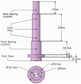
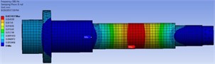
To predict the dynamic response with all sensational loads, the mathematical models of chuck (chuck standard B6151sc) and motor-rotor were coupled with the FEM model. For simplification, the models of motor-rotor and chuck were displayed as a point mass (MASS21element) with remote type connection under inertia load effects. The bearings were modeled as 2D elastic spring-damper element (COMBI214) with ground-to-body Type connection. The locations of point mass and bearings on 3D model of MMS for FEM analysis is shown in Fig. 1. The bearings stiffness was estimated according to the bearings specifications, which is 4.5E5 N/mm for front bearing and 3.5E5 N/mm for back bearing. To fix degree of freedom in axial direction; the displacement constraint was added at bearings positions. The entire FEM has been meshed by considering the magnitude and accuracy of the design, which created the mesh size of 10 mm for whole FEM with type element size. The analysis was carried out under excitations of rotating mass of chuck and motor-rotor within the excitation frequency range of 100-4000 Hz.
Fig. 1The location of point mass and spring-damper element on 3D FEM model
2.1. Parametric optimization
In the final design stage, a design’s performance is greatly influenced by its shape and size. Parametric optimization (PO) can be used to help designers for determining the optimal shape and dimensions of a structure. In general, PO involves minimizing an objective function of the Design-Variables (DVs) subjected to a given set of design constraints. So, the FEM developed in Section 2 was used to generate the DOE. The experiments were conducted according to the constraints displayed in Eq. (2) to determine structure Weight () and Max-Deformation (MD). The definitions of the DVs used for these experiments are reported in Table 1. The experiments were conducted through 65 experimental runs based on BBD experimental method. After repeating the experiments many times, the best results have been considered for RS evaluation:
To find the levels of .
That minimize the weight () , where: is density, is area, is length, and is the element number.
The subjected constraints are: 0.032, , , , , , , .
Table 1The DVs and their definitions
DVs | The definition |
[44 mm] | The motor-rotor seat spindle shaft inner diameter |
[44 mm] | The rear bearings seat spindle shaft inner diameter |
[51 mm] | The front bearing seat spindle shaft inner diameter |
[200 GPa] | The young’s modulus of elasticity |
[7450 kg·m-3] | The density of the structural material |
[12 kg] | The rotating unbalanced mass of the workpieces-holder |
[15 kg] | The rotating unbalanced mass of the motor-rotor |
3. Results and discussions
3.1. Effects of DVs on forced vibration response
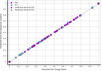
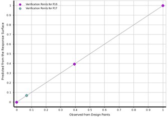
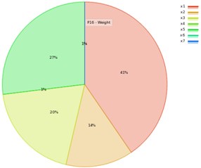
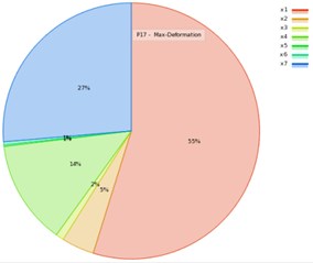
In this study, the RS method is used to evaluate the effect of DVs on the forced vibration response. The goodness fit curve shown in Fig. 2 is plotted to test the quality of RS evaluation for , and MD. Fig. 2(a) showed that the most of points are on the underline, as well in Fig. 2(b) all the verification points are greatly close to the observed-values. Therefore, the RS model is able to predict most values of design points including the verification points. The contributions of the variables on the output response are plotted in Fig. 3, which shows the DV with higher input percentage has a robust effect on the (P16), and MD (P17). Fig. 3(a) showed that the effect of factor on the output response is the first, the factor is the second, the factor is the third, and factor is the fourth. Similarly, in Fig. 3(b), it can be noted that the outcome of factor on the MD is the first, the factor is the second, and the factor is the third. Among these factors the contribution of on output response is the largest when compared to others DVs. Accordingly, the motor-rotor seat inner diameter () and material density (), and rotating unbalance-mass () are the vital factors that entirely control the output responses for MMHS.
Fig. 2The predicted from RS vs. observed from the design points: a) learning points, b) verification points
a)
b)
Fig. 3The effects of DVs on output response: a) the structure weight, b) the max-deformation
a)
b)
3.2. The optimum FEM
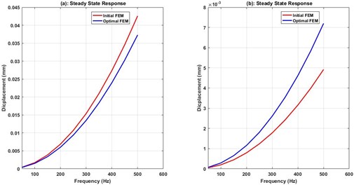
The optimization draws information from the RS; which dependent on the quality of RS evaluation. There are many RS-based optimization methods, such as Screening and Malti-Objective-Genetic-Algorithm (MOGA). An iterative MOGA provides more refined method than Screening; therefore, it’s more suitable for calculating global min\max. By considering MOGA method, the objective function and constraints were adjusted based on Eqs. (7, 8). The algorithm has generated the three candidates-points. The optimal output responses and their variation from the reference were reported in Table 2. From Table 2, it can be seen that there are percentage variation for output responses with regard to initial reference in candidates-point 1, and 2, since its zero in candidates-points 3. The vibration-behavior of optimum FEMs were obtained by creating and updating (real calculation) the DVs of candidates-points with verification point as shown in Fig. 4. The outcome obtained regard to the real solve for verification shown in Fig. 4(d) is comparable to RS optimization results of Fig. 4(a), (b), and (c). In Fig. 9, also it showed that the maximum vibration-response calculated is at motor-rotor rotating force position, while it minimum at front bearings position. Based on the smallest percentage variant detailed in Table 2, the candidates-point 3 remains the best solution that satisfied the design requirement with least computational error. To identify the efficiency of RS model, the optimal FEM is compared with the reference point as plotted in Fig. 5. From Fig. 5, it can be noted that the damped FRF is comparable to its initial model. The FRF improved in span between bearings, while it increased in spindle nose. As results, the structural-weight regard to the spindle shaft has been decreased by 12.5 % when compared to its reference weight (18.3 kg). Thus, the proposed optimization method is significant in terms of materials and energy resources saving.
Table 2The output responses and their variation from the reference
Optimal Points | Structure Weight | Max-deformation | ||
Response | Variant | Response | Variant | |
1 | 16.033 kg | –0.14 % | 0.0289 mm | 0.22 % |
2 | 16.043 kg | –0.07 % | 0.0286 mm | –0.62 % |
3 | 16.055 kg | 0.00 % | 0.0288 mm | 0.00 % |
Verification | 16.066 kg | 0.05 % | 0.0274 mm | –0.94 % |
Fig. 4The FEMs mode shapes after optimization
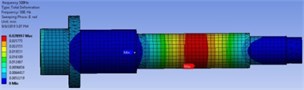
a) First candidates-point
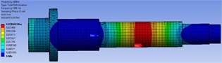
b) Second candidates-point
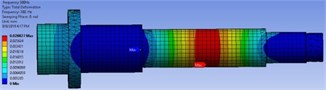
c) Third candidates-point
d) DO-based verification point
Fig. 5Compares initial and optimal behavior of FRF, a) span between bearings, b) spindle nose
The machine tool spindle design requirement for stiffness can be used to verify the FEM, by comparing the values of dimensionless amplitude of span between bearings. So, the confirmation of FEM is done by comparing numerical solutions to related results carried out in previous work [3]. First, the Static Deformation (SD) of span () between bearings is calculated using the theoretically constrained function of 0.0002. Secondly, the Max-Deformation (MD) of span between bearings is defined for finite element model at lower operating frequency. Then, the dimensionless amplitude is determined by computing the ratio of MD to SD. The computational results indicated that the FEM developed is comparable to experimentally validated results found in [3]. Wherein the dimensionless amplitude calculated are 0.34 for presented FEM, and 0.76 for publication [3], the slightest variation noted in finding may turned into a different in boundary conditions.
4. Conclusions
In this work, dynamic design optimization method for MMS subjected to a number of rotating unbalanced forces effects is considered. Linear forced-Rotordynamic analysis with design explorer method is adopted to simulate the output-response. The DVs and theirs constrains were definitely selected and applied to develop the DOE for design-space exploration. The BBD method, because of its good organization in providing much information in a minor number of required statistical experiments was used to generate the DOE. The effect of DVs on dynamic performance of MMS and their levels optimization were evaluated by utilizing the RS method. The results showed that the spindle shaft inner diameter of the motor-rotor seat and its rotating unbalanced mass, and modulus of elasticity have the highest contribution in effect on the dynamic of MMHS. The structural-weight of spindle shaft has been improved by 12.5 % saving when comparing to its initial weight. As well, it is found that the proposed optimization method not only improves the structural weight of MMHS, but also the potential saving can be achieved in term material and energy resource. Finally, the FEM has been confirmed through related experimentally validated results in the literature.
References
-
Didier J., Sinou J.-J., Faverjon B. Study of the non-linear dynamic response of a rotor system with faults and uncertainties. Journal of Sound and Vibration, Vol. 331, 2012, p. 671-703.
-
Xul J., Zheng X., Zhang J., Liu X. Vibration characteristics of unbalance response for motorized spindle system. Procedia Engineering, Vol. 174, 2017, p. 331-340.
-
Huang P., Lee W. B., Chan C. Y. Investigation of the effects of spindle unbalance induced error motion on machining accuracy in ultra-precision diamond turning. International Journal of Machine Tools and Manufacture, Vol. 94, 2015, p. 48-56.
-
Ahmed E. A. I., Shusen L. Optimization of factors affecting vibration characteristics of unbalance response for machine motorized spindle using response surface method. Mathematical Problems in Engineering, Vol. 2019, 2019, p. 1845056.
-
Zhou J., Di L., Cheng C., Xu Y., Lin Z. A rotor unbalance response based approach to the identification of the closed-loop stiffness and damping coefficients of active magnetic bearings. Mechanical Systems and Signal Processing, Vol. 66, Issue 67, 2016, p. 665-678.
-
Wu Q., Sun Y., Chen W., Chen G., Bai Q., Zhang Q. Effect of motor rotor eccentricity on aerostatic spindle vibration in machining processes. Proceedings of the Institution of Mechanical Engineers, Part C: Journal of Mechanical Engineering Science, Vol. 232, 2017, p. 1331-1342.
-
Lin C.-W., Tu J. F. Model-based design of motorized spindle systems to improve dynamic performance at high speeds. Journal of Manufacturing Processes, Vol. 9, 2007, p. 94-108.
-
Liu J., Chen X. Dynamic design for motorized spindles based on an integrated model. The International Journal of Advanced Manufacturing Technology, Vol. 71, 1961, p. 1974-2014.
-
Lu L., Chen W., Wu B., Gao Q., Wu Q. Optimal design of an aerostatic spindle based on fluid-structure interaction method and its verification. Proceedings of the Institution of Mechanical Engineers, Part J: Journal of Engineering Tribology, Vol. 230, 2015, p. 690-696.
-
Park Seong Jin L.-C.-M., Hwang Young Kug Lightweight design of 45 000 r/min spindle using full factorial design and extreme vertices design methods. Journal of Central South University of Technology, Vol. 18, 2011, p. 153-158.
-
Lin C.-W. An application of Taguchi method on the high-speed motorized spindle system design. Proceedings of the Institution of Mechanical Engineers, Part C: Journal of Mechanical Engineering Science, Vol. 225, 2011, p. 2198-2205.
-
Lin C.-W. Simultaneous optimal design of parameters and tolerance of bearing locations for high-speed machine tools using a genetic algorithm and Monte Carlo simulation method. International Journal of Precision Engineering and Manufacturing, Vol. 13, 1983, p. 1988-2012.
-
Ahmed E. A. I., Shusen L., Helal W. M. K. Optimization of parameters influencing the quality loss of machine motorized spindle using design exploration and Taguchi methods. International Journal of Engineering Research in Africa, Vol. 41, 2019, p. 26-36.
About this article

The authors gratefully thank the technical support that provided by College of Mechanical and Electrical Engineering, Northeast Forestry University, Harbin, China, during this work.
