Abstract
In High-Speed Milling Process (HSM) the machining precision is directly affected by spindle bearing system which has a crucial role and it impacts directly the dynamic performance of the machining system. This study is about an accurate simulation of such system response. In fact, the Timoshenko beam theory with different circular sections is used to propose a finite element model of the spindle system. The effect of the rolling bearings and the gyroscopic moment at high speeds as well as the centrifugal forces and the cutting forces are considered in the formulation. The rigid and flexible movements of the spindle are taken into account. The dynamic responses of tool-tip under the dynamic cutting forces are numerically investigated.
1. Introduction
Commonly used in machining processes the high speed milling (HSM) machines have an important place in industrial manufacturing. They are characterized in fact by low cutting forces and high material removal rate to lead to quality of the product and closer tolerances. Unfortunately, the process instability affects badly the product finish surface and reduces dimensional accuracy and increases the rate of tool wear and may leads to the breakage of the spindle-tool unit.
Large displacement of the tool is the origin of high noise and rapid wear of both cutting tool and machine tool. It is the result of chatter arising from multiple causes and the most important one is called regenerative chatter produced by the regeneration of the work piece surface waviness.
This instability phenomenon called chatter is widely studied by [1-4] to leads to the development of the stability lobes diagrams in milling process which allow to choose the maximum axial depth of cut for a given spindle speed associated with a chatter free machining.
Altinas and Budak [5-7] developed a stability method which leads to analytical determination of stability limits. The method was verified by experimental and numerical results and applied to the stability of ball end milling then extended the frequency domain stability models to cutters with arbitrary geometries [8] and to variable pitch cutters [9] and prediction of surface location errors in flexible milling systems [10]. The major efforts of these researches focus on specific cutting force identification and chatter avoidance and determination of cutting conditions with a maximum of material remove rate.
Many authors have investigated analytically and experimentally the dynamic behavior of machine tool spindle-bearing systems. They show that spindle dynamics are influenced by a large number of factors such as holder characteristics [11] and spindle shaft geometry and drawbar force [12] as well as the stiffness and damping provided by the bearings [13]. Contrary to bearing properties and spindle rotor dynamics which depend on spindle speed most of these factors are independent of spindle speed and rotating systems have been successfully modeled through rotor-dynamics studies [14, 15].
Several previous research works considered that over a full spindle speed range the dynamic characteristics of the spindle-tool set do not change substantially. However, for high speed milling operations there will be changes due to gyroscopic moments and centrifugal forces on both bearings and spindle shaft which will give rise to variation in dynamic behavior of the spindle set. Several other factors influence this behavior such as holder characteristics and spindle shaft geometry and drawbar force which are independent of spindle speed [16-18]. A high speed electro-spindle supported by rolling bearings has been designed and modeled by Patil et al. [19]. They have presented an analytical model for predicting the effect of a localized defect on the ball bearing vibrations. The effect of the defect size and its location has been investigated. The numerical results obtained have been compared with experiments.
The bearings stiffness and damping factors are strictly related to loads and spindle speed [20]. In this context Nelson [21] developed a rotor-bearing model of the spindle set using Timoshenko beam theory taking into account shear deformation. His formulation has been used by Rantatalo et al. [22] for stability predictions and to validate experimental approaches of a milling machine spindle.
Kang et al. [23] analyzed the effects of design parameters on static and dynamic performance of spindle-bearing systems by using Finite Element Method (FEM). The parameters considered in their case studies included journal diameter and span ratio and bearing stiffness for static performance but for dynamic performance only the bearing stiffness was considered. The only high speed effect included in their FEM was gyroscopic moments. Li and Shin [24] published a paper to investigate the effects of bearing configuration on the dynamics of high speed spindles. An integrated Finite Element Method (FEM) model has been developed by Lin and Tu [25] to combine the changes of the bearing stiffness and shaft rigidity to determine the overall spindle-bearing system dynamics.
In the previous theoretical studies, the spindle was considered as flexible or rigid bodies but in our study the flexible and the rigid motions are combined. The finite element modeling is developed to study a real system case. The nonlinear forces exerted by rolling bearings on the inner races based on the Hertz contact theory and the dynamic cutting forces for milling operation are formulated. Using Lagrange formalism, the dynamic equation of motion is obtained taking into account the centrifugal force and gyroscopic moments. The implicit Newmark algorithm coupled with Newton Raphson iterative method is used to solve the nonlinear differential equation iteratively in order to analyze the influence of some parameters on the dynamic response of the spindle.
2. Modeling of spindle machining
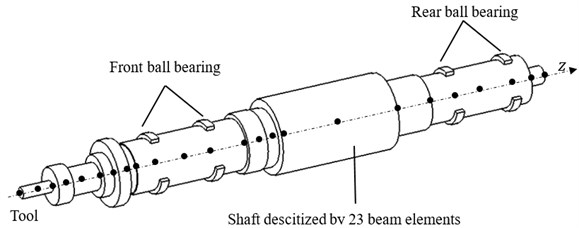
The study consists on analyzing structural vibrations generated by HSM spindle supported by four ball bearings (two front bearings and two rear bearings) as shown by Fig. 1. Bearings outer races are fixed in the rigid support (logging) while the inner races are rigidly assembled to the rotating shafts. The spindle is discretized to 23 beam elements using the Timoshenko theory taking into account both elastic and rigid motion. The centrifugal effect and the gyroscopic moment are taken into account. The bearing unbalance and cutting effects are defined as forces exerted on the spindle and their expressions are detailed in the next sections.
Fig. 1Spindle-tool system modeling
2.1. Spindle modeling
In order to define the mass, the stiffness, the gyroscopic and the centrifugal matrices of one beam element (spindle element), we apply the Lagrange formalism on the kinetic energy of Eq. (1) and the strain energy of Eq. (2) written using elastic degrees of freedom and rigid degrees of freedom as follows:
where, and are the displacements due respectively to rotor bending and rotor shear and , , , and are respectively the density the area the inertia moment the length of the element and the rotational speed of the spindle. , and are respectively the Young’s modulus the correction factor and the shear modulus.
The different expressions of various matrices corresponding to a beam element are computed and given in Appendix.
2.2. Rolling bearing modeling
The bearings effects are introduced as forces and moments. In fact, each rolling bearing placed in the th node, exerts forces and moments computed using the Hertz contact theory [13]:
where, , and represent respectively the ball angular position the loaded contact angle and the radial position of the outer race curvature centre of the th ball in the th rolling bearing. and are respectively the balls number and the Hertz contact constant deduced from curvature radius of the elements in contact. is the elastic deformations of the th ball [13] given by:
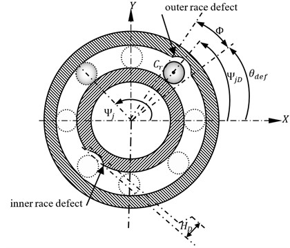
where is the Heaviside function while and are respectively the loaded and unloaded distance between inner and outer races curvature centers for each rolling element . is a scaling default of an inner or an outer race as shown by Fig. 2. This defect is defined by [19] as a half sinus written as following:
with is the defect height and is the defect size and denotes the defect position written for inner and outer race respectively as:
The total actions exerted by the bearings on the spindle in all system degrees of freedom will be the sum of the forces exerted by each rolling bearing given by Eq. (3).
Fig. 2Defected ball bearing modeling
2.3. Unbalance force modeling
Considered as one of the main causes of vibration of rotating machines and particularly spindles, the unbalance is defined as a non-coincidence between the spindle revolution axis and rotation axis.
The unbalance mass is at the origin of unbalance force considered as an applied external force expressed thanks to angular velocity and unbalance center coordinates as following:
where and the unbalance vector as given in Appendix.
2.4. Cutting force modeling
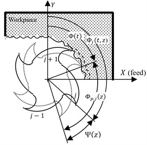
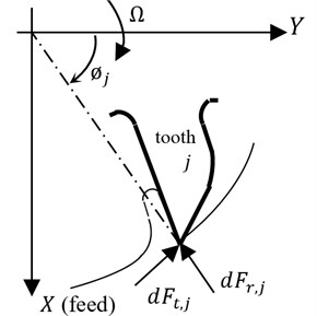
To take into account, in our study, the contribution of all the forces of each element of each cutting edge in cutting process, the cutting edge is discretized using a mechanical approach. Indeed, the cutting forces model on one differential element takes into account the shearing forces and the edge forces by means of a tangential and radial component as shown by Fig. 3. These components depend on the correspondent cutting coefficients as well as the instantaneous chip thickness and the differential width of cut .
Consider a cutter element with a differential height at axial location of flute number . The instantaneous chip thickness removed by the differential cutting edge element is defined as:
where is feed-per-tooth and and are deflections of tool-tip at the present time and and are deflections of tool-tip at the previous time. The delay between is defined as follow:
with the is the number of teeth of the tool.
Fig. 3Elemental cutting forces of peripheral milling
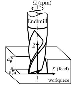
a) Milling operation
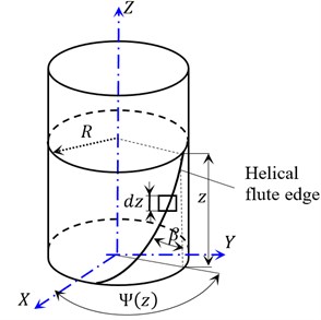
b) Helical flute edge geometry
c) Schematic representation of the geometrical parameters
d) Differential tangential and radial forces
The instantaneous immersion angle of the cutting edge for the flute at elevation at time is expressed by:
where is the angular position of the reference flute ( 0) at elevation 0.
The lag angle between the flute tip and edge at elevation is and the pitch angle is for cutters which have constant helix angle (), tool radius (), and pitch angles.
For a point on the (th) cutting tooth the differential milling forces corresponding to an infinitesimal element thickness () in the tangential direction , and radial direction is given by:
where and are respectively the tangential and radial specific cutting forces and is a step function which is used to illustrate whether the current differential cutting edge is involving in cutting process or not and can be expressed by:
where and are the entry and exit angles of the cutter.
Through coordinate transformation the cutting forces in the global coordinate system can be evaluated as following:
By integrating along the axial depth of cut and summing for all in-cut teeth the overall cutting forces acting on the cutter for a certain indexed angle can be given as:
where and are respectively the number of teeth and the number of cutter elements in direction.
2.5. Motion equation system
The equation of motion describing the dynamics of the system which includes all system components can be expressed in a general form as follows:
where flexible and rigid movements are respectively indicated by the indices and and the mass matrix is [] while [] is the gyroscopic matrix associated both to the rigid movement and used to define the coupling between flexible and rigid movements (given in Appendix).
The centrifugal matrix [] is also given in Appendix. The defective bearings apply force defined in Section 2.2 and the unbalance and the cutting forces generate respectively defined in Section 2.3 and defined in Section 2.4. The vector of degrees of freedom is associated to different nodes and it is caused by elastic and rigid movements.
3. Numerical results and discussion
The Newmark method coupled with the Newton Raphson iterative method is used to resolve the nonlinear equation of motion Eq. (15). Both rigid and elastic displacements are taken into account in all numerical results.
Table 1Parameters of the studied system
Tool parameters | Symbol | Value | Unit |
Number of teeth | 2 | ||
Tool radius | 10 | mm | |
Feed per tooth | 0,12 | mm/tooth | |
Cutting parameters | |||
Tangential cutting force parameter | 462 | N/mm2 | |
Radial cutting force parameter | 38.6 | N/mm2 | |
Spindle dynamics | |||
Spindle rotational speed | 20000 | rpm | |
Rotor length | 651.95 | mm | |
Rotor moment of inertia | 5 10-4 | Kg.m2 | |
Spindle mass | 16.03 | Kg | |
Young’s modulus | 2.1 1011 | Pa | |
Density | 7.85 | g/cm3 | |
Ball bearings: NHBB#CXMC-1112DXC77 | |||
Contact angle | 15 | degrees | |
Ball diameter | 8.73 | mm | |
Pitch diameter | 77.5 | mm | |
Balls number | 23 | ||
Characteristics of healthy rolling bearing are cited in Table 1 and used to validate the model for a milling operation whose parameters are listed, also, in the same table.
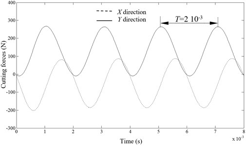
Fig. 4 presents the cutting forces in both and directions, for a system rotating velocity equal to 15000 rpm. We note a sinusoidal behavior for both forces having 500 Hz as frequency (2×10⁻³ as period). In fact, this last correspond to 2×, double rotating frequency, originating from the tool teeth number (2 teeth). The cutting force in the normal direction is bigger than the force in the feed direction. But, the peak to peak amplitude remains constant. Those results are confirmed with experimental ones given by Faassen [2].
Fig. 4Cutting forces direction
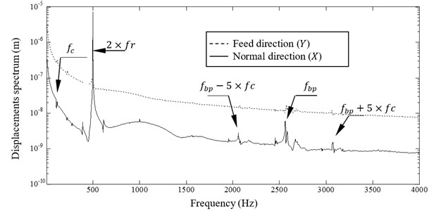
By examining the Fourier transform of the normal and feed displacements of Fig. 5 we note the presence of a dominant peak occurring at 2× caused by the cutting force variation in time as shown by Fig. 4. Another peak appears at 2562 Hz corresponding to ball passage frequency of the rear and front bearings which has a lower vibratory level. This last provides from the variation of the angular position of balls when the bearings are in movement, which causes the variation of the total external load in time (when each bearing rotates one round/). The lowest level peak at 111.4 Hz corresponds to the cage frequency (corresponding to one round balls rotation). Their harmonics are also observed. We note also a modulation between the ball passage frequency and the cage frequency .
Fig. 5X and Y directions displacements
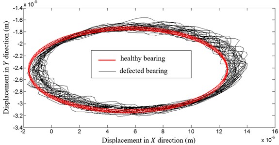
We introduce now an outer race default, as defined in Section 2.2., having a defect height 10-6 m, a defect size 0.1778×10⁻³ and a null initial position. When we examine the orbit of the milling tool for the two cases: healthy and defected bearings (given by Fig. 6), we note an excessive fluctuation of the orbit for a defected rolling bearing case, which causes a bad quality surface of the milled workpiece. We note, also, for a bearing default case, a shifting in the orbit center in direction. This shifting is better viewed in Fig. 7, presenting the first node displacement in direction for the two cases. In fact, this shifting equal to 10-6 m is equal to the default height.
Fig. 61st node orbit
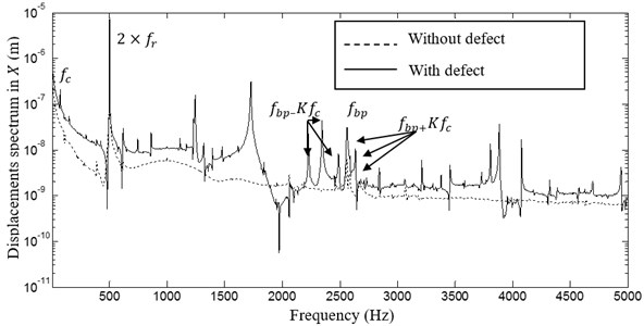
The FFT transform of first node displacement in direction for the healthy and unhealthy bearings is given by Fig. 8. By examining the spectrums, we note a higher vibratory level in the defected case. Also we remark an increase in the ball passage frequency level. In fact, the defect is periodic with a frequency equal to the ball passage frequency. The modulation between the ball passage frequency and the cage frequency is very important in the defected case which causes an excessive displacement fluctuation (as observed in Fig. 6) translated to a bad quality surface as observed in reality.
Fig. 71st node displacement in X direction (with and without defect)
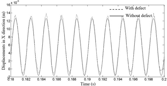
Fig. 8Spectrum of the 1st node displacement in X direction (with and without defect)
In order to show the bearings characteristics incidence, we choose NHBB#CXMC-1112DXC77 as front bearings with the characteristics by given in Table 1 and NHBB#CXMC-1109DXC77 as rear bearings with the same contact angle and a ball number equal to 19. The pitch and ball diameters are respectively 60 mm and 7.94 mm. A comparison between the spectrums of the 1st node displacement in direction of different and identical studied bearings is given in Fig. 9. The dominant frequency corresponding to the running frequency is noted in the two study cases. The ball passage frequencies of each rolling bearing are observed in the case of different bearings which appear at 2562 Hz and 2071 Hz. The two cages frequencies and the modulation are also viewed.
Fig. 9Spectrum of the 1st node displacement in X direction (different and identical bearing)
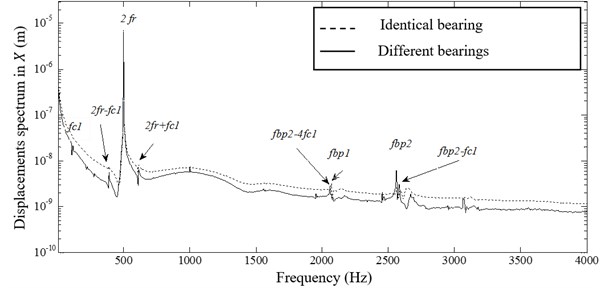
Fig. 10Influence of the number of cutter teeth on the displacements
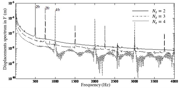
Fig. 11Time response of the displacement along X axis
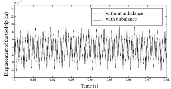
Fig. 12Frequency spectrum of the displacement along the X axis for a system with and without unbalance
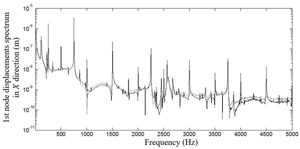
Fig. 10 presents the spectrum of the 1st node displacement in direction for identical bearings and different cutter teeth values which vary from 2 to 4. The dominate frequency producing at is always observed (as explained for Fig. 5) but the vibratory level is decreasing when the teeth number is increasing. Indeed, the total cutting force is sheared between the teeth. Then the generated force by each tooth on the manufactured part (i.e. the shock on the spindle) decreases when the teeth number increases.
A comparative study for a spindle with and without unbalance is investigated with a teeth number equal to 3 and identical rolling bearings. The time response of the displacement in direction of the tool tip is shown by Fig. 11. The maximum response of the tool tip in absence of unbalance is 7 µm but it reaches 8.2 µm when we introduce an unbalance. Both of vibratory levels have the same period of time. By higher vibration levels unbalanced spindle promotes maximum form errors on finished surface of manufactured part which is in concordance with the reality.
By examining the spectrum of respective displacements in Fig. 12 we note the presence of the cutting frequency produced at 750 Hz. The ball passage and the cage frequencies are also founded. For the system having an unbalance we note also the presence of the rotating shaft frequency corresponding to 500 Hz.
4. Conclusion
A dynamic modeling of high speed spindle supported by rolling bearings is established in the case of high speed milling process. Using the finite element method, we consider the gyroscopic effect as well as the centrifugal forces and the coupling between rigid and elastic modes in the global equation of motion. The implicit Newmark algorithm coupled with Newton Raphson iterative method is used to solve the nonlinear differential equation of motion.
The cutting force model was used to predict the forces acting on the tooltip during peripheral milling process. The results of this simulation show a sinusoidal behavior and the cutting force in the normal direction is larger than the force in the feed direction. The examination of the spectrum of the normal and feed directions shows the presence of three characteristics frequencies such as two times the running frequency and the cage frequency and the ball passage frequency. The orbit of tool tip in - plane was plotted with healthy and defected bearings. The presence of defects causes an excessive vibrations and the modulation between the ball passage and the frequencies were more important. Simulated results show also that the number of cutter teeth strongly affects the frequencies contents of the tooltip.
References
-
Chen L. W., Ku D. M. Dynamic stability analysis of a rotating shaft by the finite element method. Journal of Sound and Vibration, Vol. 143, Issue 1, 1990, p. 143-151.
-
Faassen R. P. H., Van De Wouw N., Oosterling J. A. J., Nijmeijer H. Prediction of regenerative chatter by modelling and analysis of high-speed milling. International Journal of Machine Tools and Manufacture, Vol. 43, 2003, p. 1437-1446.
-
Altintas Y., Weck M. Chatter stability of metal cutting and grinding. International Academy for Production Engineering (CIRP) Annals – Manufacturing Technology, Vol. 53, Issue 2, 2004, p. 619-642.
-
Gagnol V., Le T. P., Ray P. Modal identification of spindle-tool unit in high-speed machining. Journal of Mechanical Systems and Signal Processing, Vol. 25, Issue 7, 2011, p. 2388-2398.
-
Altintas Y., Budak E. Analytical prediction of stability lobes in milling. International Academy for Production Engineering (CIRP) Annals – Manufacturing Technology, Vol. 44, Issue 1, 1995, p. 357-362.
-
Budak E., Altintas Y. Analytical prediction of chatter stability in milling – part I: general formulation. Transactions of the ASME, Journal of Dynamics Systems, Measurements and Control, Vol. 120, Issue 1, 1998, p. 22-30.
-
Budak E. Analytical models for high performance milling – part II: process dynamics and stability. International Journal of Machine Tools Manufacture, Vol. 46, Issues 12-13, 2006, p. 1489-1499.
-
Altintas Y., Lee P. A general mechanics and dynamics model for helical end mills. International Academy for Production Engineering (CIRP) Annals – Manufacturing Technology, Vol. 45, Issue 1, 1996, p. 59-64.
-
Altintas Y., Engin S., Budak E. Analytical stability prediction and design of variable pitch cutters. Transactions of the ASME, Journal of Manufacturing Science and Engineering, Vol. 121, Issue 2, 1999, p. 173-178.
-
Eksioglu C., Kilic Z. M., Altintas Y. Discrete-time prediction of chatter stability, cutting forces, and surface location errors in flexible milling systems. Transactions of the ASME, Journal of Manufacturing Science and Engineering, Vol. 134, Issue 6, 2012, p. 1-13.
-
Agapiou J., Rivin E., Xie C. Toolholder/spindle interfaces for CNC machine tools. International Academy for Production Engineering (CIRP) Annals – Manufacturing Technology, Vol. 44, Issue 1, 1995, p. 383-387.
-
Smith S., Jacobs P., Halley J. The effects of drawbar force on metal removal rate in milling. International Academy for Production Engineering (CIRP) Annals – Manufacturing Technology, Vol. 48, Issue 1, 1999, p. 293-296.
-
Abbes M. S., Hentati T., Maatar M., Fakhfakh T., Haddar M. Dynamic analysis of helical gears supported by rolling element bearings. Journal of Theoretical and Applied Mechanics, Vol. 41, Issue 1, 2011, p. 33-50.
-
Nelson H. D., Mc VaughJ. M. The dynamic of rotor-bearing systems using finite elements. Transactions of the ASME, Journal of Engineering for Industry, Vol. 98, Issue 2, 1976, p. 593-600.
-
Kiral Z., Karagulle H. Vibration analysis of rolling element bearings with various defects under the action of an unbalanced force. Mechanical Systems and Signal Processing, Vol. 20, Issue 8, 2005, p. 1967-1991.
-
Ruhl R. L. Dynamics of Distributed Parameter Rotor System: Transfer Matrix and Finite Element Techniques. Ph.D. Thesis, Cornell University, 1970.
-
Jack L. B., Nandi A. K. Support vector machines for detection and characterization of rolling element bearing faults. Proceedings of the Institution of Mechanical Engineers, Journal of Mechanical Engineering Science, Vol. 215, 2001, p. 1065-1074.
-
Noel D. Modélisation du Comportement Dynamique des Broches UGV et Validation Expérimentale. Stage II of the Master Thesis, Central School of Nantes, 2010, (in French).
-
Patil M. S., Mathiew J., Rajendrakumar P. K., Desai S. A theoretical model to predict the effect of localized defect on vibrations associated with ball bearing. International Journal of Mechanical Sciences, Vol. 52, Issue 9, 2010, p. 1193-1201.
-
Jorgensen B. R., Shin Y. C. Dynamics of spindle-bearing systems at high speeds including cutting load effects. Journal of Manufacturing Science and Engineering, Vol. 120, Issue 2, 1998, p. 387-394.
-
Nelson H. D. A finite rotating shaft element using Timoshenko beam theory. Transaction of the ASME, Journal of Mechanical Design, Vol. 102, Issue 4, 1980, p. 793-803.
-
Rantatalo M., Aidanpaa J. O., Goranssonn B., Norman P. Milling machine spindle analysis using FEM and non-contact spindle excitation and response measurement. International Journal of Machine Tools and Manufacture, Vol. 47, Issue 7, 2006, p. 1034-1045.
-
Kang Y., Chang Y. P., Tsai J. W., Chen S. C., Yang L. K. Integrated C.A.E. Strategies for the design of machine tool spindle bearing systems. Finite Elements in Analysis and Design, Vol. 37, Issues 6-7, 2001, p. 485-511.
-
Li H., Shin Y. C. Analysis of bearing configuration effects on high speed spindles using an integrated dynamic thermo-mechanical spindle model. International Journal of Machine Tools and Manufacture, Vol. 44, Issue 4, 2004, p. 347-364.
-
Lin C. W., Tu J. F. An integrated thermo-mechanical dynamic model to characterize motorized machine tool spindles during very high speed rotation. International Journal of Machine Tools and Manufacture, Vol. 43, Issue 10, 2003, p. 1035-1050.
Cited by
About this article

