Abstract
A nonlinear dynamic model of spindle-cutter coupling system under cutting force, which takes into account the cutter stiffness and the nonlinearity of bearing clearance, is established. Analysis of the cross-section of a two-flute end mill is conducted to determine cutter stiffness. Then, the calculated cutter stiffness is introduced into the nonlinear dynamic model of coupling system. In the modeling of cutting force, the cutting width takes into account the cutter tip displacement. Moreover, nonlinear dynamic characteristics of spindle-cutter coupling system are studied and the effects of bearing clearance on the response of cutter tip are discussed as well, considering unbalanced force. The numerical results show that the bearing clearance strongly affects the equilibrium position. With different values of bearing clearance and rotation speed, the responses of cutter tip exhibit periodic, quasi-periodic and chaotic characteristics. Dynamic characteristics of spindle-cutter system depends on the bearing clearance and rotation speed. The proper bearing clearance and rotation speed should be chosen to ensure a stable cutting and high cutting rate according to the bifurcation diagram. The response of the cutter tip is a quasi-periodic motion when the cutting force is considered. The time-domain response of cutter tip predicted by nonlinear dynamic analysis can provide the basis for machining error prediction.
1. Introduction
With the development of manufacturing industry, the machining speed has increased considerably over the past years and the spindle tool system is one of the key components in ensuring machining precision and accuracy. Sometimes the spindle system is in unusual working condition. Higher demands for nonlinear dynamic characteristic of spindle system are required. Therefore, research on nonlinear dynamic characteristic of spindle-cutter system is necessary.
Yu et al. [1] conducted nonlinear dynamic analysis of ultra-high speed grinding spindle system by using digital analysis methods, and dynamic characteristics of liquid hybrid bearing were analyzed by using Fluent software. Based on Hertz contact force formulation, Zhang et al. [2] established a six-degree-of-freedom model for investigating a machine-tool spindle system supported with ball bearings. The effects of negative bearing clearance on the dynamic response and stability of the machine tool spindle system with unbalanced force were investigated. Gao et al. [3] conducted unstable islands and bifurcation analysis in a spindle milling system, and dynamic milling forces were considered [3, 4]. Floquet theory was applied to investigate the stability of the periodic solution in [5]. A non-uniform continuous Timoshenko beam model for spindle system with nonlinear and nonsmooth boundaries was established in [6]. Galerkin method was used to discretize the governing nonlinear partial differential equations. Zhang et al. [7] considered effects caused by bearings and the interface of spindle-holder on the vibration response of spindle system. Si et al. [8] considered the nonlinear bearing force based on Hertz theory. Nonlinear bearing force caused by surface waviness on raceway was considered in [9]. Nonlinear dynamic characteristic of the spindle system was studied via numerical simulation in [8, 9], respectively. Lioulios et al. [10] studied the effects of rotational speed changes on dynamic characteristic of rotor-bearing system. In practical engineering applications, the vibration of cutter tip is always concerned. However, in the aforementioned researches, the vibration of cutter in a spindle system has received little consideration. Gao et al. [11] established a dynamic model of spindle-cutter coupling system including the gyroscopic effects and shear deformation. Based on Riccati transformation, the dynamic characteristic of the system was analyzed by using the whole transfer matrix method; however, the research focused on the vibration mode of the system and did not involve transient response of cutter tip.
In this paper, a nonlinear dynamic model of spindle-tool coupling system based on the second Newton's law is established considering milling cutter stiffness, cutting force, and clearance of bearing. According to the classic method of elastic theory, based on cross-sectional analysis, the cutter stiffness is determined and it is added into the nonlinear dynamic model. The influence of bearing clearance to the system is discussed. The displacement of cutter tip is accumulated into cutting width in the model of cutting force. Transient response of cutter tip is predicted and analyzed under cutting force as well.
2. Nonlinear dynamic model of the spindle-cutter coupling system
Fig. 1 shows the typical spindle-cutter coupling system for machine tools. The rotor of spindle is supported by two pairs of angular contact ball bearings. An integral induction motor is located between the front and rear bearings to drive the spindle system. Since the main vibration affecting machining precision is that normal to the machining plane, the proposed model only considers the vibration in this direction. Therefore, spindle-cutter system is simplified to a five-degree-of-freedom system as shown in Fig. 2.
Fig. 1A schematic of the spindle-cutter coupling system
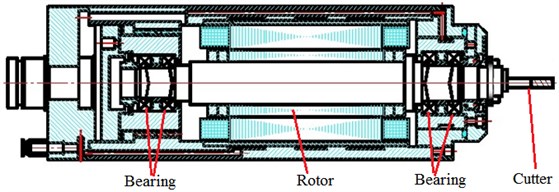
Fig. 2Nonlinear dynamic model of spindle-cutter coupling system
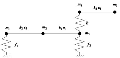
Where, , and are discrete masses of the spindle; and are discrete masses of the milling cutter; and are stiffness of spindle. is coupling stiffness at spindle-cutter interface determined by the semi analytical method combining classic elasticity theory with Yoshimura integral method [12]; is stiffness of milling cutter; and are damping coefficient of spindle; is damping coefficient of milling cutter; and are bearing load.
In this paper, the rotation speed 20044 r/min. The equivalent mass ( (1, 2,…, 5)) and equivalent stiffness ( ( 1, 2, 3)) are identified by the equivalent method described in [13]. The damping coefficient is assumed to be proportional to the corresponding stiffness, and (1, 2, 3).
According to the second Newton’s law, dynamic differential equation of spindle-cutter system is as follows:
where , , , and are displacements of nodes corresponding to the mass shown in Fig. 2; the downward direction is the positive direction. 3.21×10⁻⁴ mm is the offset of unbalance mass of spindle, and is the gravity acceleration.
3. Cutter stiffness
The cutter is usually simplified as cantilever beam [14-19], and each cross section along the axial direction is assumed as the same. In fact the error between each cross section exists because of an angle of , which is depicted in Fig. 3-4. A certain error will occur when the cross section is assumed to determine the cutter stiffness. To avoid the error, it is thus necessary to develop a method to evaluate the cutter stiffness considering the difference between the cross sections.
Fig. 3Diagram of the cutter
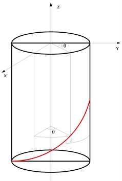
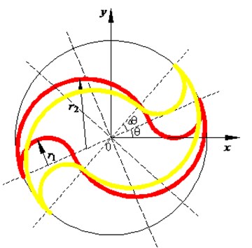
Fig. 4Cross section of two-flute end mill
All the cross sections of cutter have the same shape and each section rotates an angle of along the cutting edge relative to the neutral plane shown in Fig. 3. Defining the inertia moment relative to the neutral plane at each cross section is thus required to calculate the stiffness of the whole milling cutter.
In this research, cutter stiffness is determined by the analysis of the cross-section. The cutter has helicoidal shape, the cross section is assumed according to [20] and it is shown in Fig. 4.
A two-flute end mill is chosen as the research object, whose cross section rotates an angle of . The distance between the section and the initial section is . The cross section of cutter can be simplified as in Fig. 4. The parameter is , where and are the radius depicted in Fig. 4. The inertia moment of cross section that rotates an angle of relative to the neutral plane is given by:
From Eq. (2), it can be concluded that the inertia moment relative to the neutral plane is constant, although the cross section rotates an angle of along the cutting edge. The inertia moment of cross section is independent of the angle rotated from the initial section.
The end mill consists of cutting edge and shank, and it can be simplified as the non-uniform beam shown in Fig. 5. According to classic theories of material mechanics [21], the displacement at cutter tip under a unit force applied on the cutter tip can be obtained. The stiffness at cutter tip (i.e. cutter stiffness) is the reciprocal of the displacement, and it can be determined by:
where is length of cutting edge, is length of shank, is inertia moment of cutting edge, , is inertia moment of shank, .
The parameters of the end mill adopted in the model are listed in Table 1.
Fig. 5Model of cutter for stiffness calculation
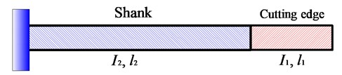
Table 1Parameters of the end mill
Parameter | Value |
Shank diameter | 12 mm |
Shank length | 20 mm |
Cutter length | 15 mm |
Cutter diameter | 12 mm |
Helix angle | 45° |
4. Nonlinearity of the bearing clearance
Angular contact bearings are generally used in machine tool spindle. A micro-gap may exist between the balls and the outer or inner ring because of the installation error or wear during spindle operation.
The support force of the bearing is expressed as [22]:
where is support force of the bearing, is displacement of bearing, is clearance of bearing, is number of balls, is diameter of ball, is preload, and is contact angle of bearing. The front bearing of the spindle is assumed as loose fit.
5. Modeling of transient cutting force
According to [23], the transient cutting force can be predicted as follows:
where and is transient cutting force in and direction, respectively. is feed of each tooth, is diameter of end mill, is helix angle of end mill, and are coefficient of cutting force in tangential and radial direction, respectively. The coefficients represent the cutting force per unit thickness and unit width, respectively and they are experimentally evaluated. is number of tooth of the cutter. is lag angle in the maximum cutting deep, is lag angle of micro element relative to cutter tooth on the bottom, is transient position angle of the th tooth, which can be expressed by:
where is a function considering effects of continuous cutting on the cutting force:
where and is angle of cutting in and cutting out, respectively. During the down milling and . The displacement of cutter tip is accumulated into the cutting width. , where is initial cutting width. In this way, the nonlinear factor of cutting force can be considered in this research.
The coefficients of cutting force and have been measured in our previous research [24] and their values are the following: 1880.0 N/mm2, 893.3 N/mm2.
6. Results and discussion
Dimensionless variables:
are introduced to normalize Eq. (1):
The dimensionless governing equation of motion of spindle-cutter system is a set of ordinary differential equations with nonlinear and nonsmooth excitation. For this system, the analytical method to study nonlinear dynamic characteristic is not available. The fourth-order Runge-Kutta method is adopted to solve Eq. (8). The relatively shorter time step is chosen to reduce the calculation error; meanwhile a certain periods are abandoned to obtain stable transient solution of the system. In this research, the time step /100 is chosen and the first 1000 periods are abandoned.
To study the effect of bearing clearance on nonlinear dynamic characteristic of the system, responses of cutter tip under different bearing clearances (i.e. , , , ) with the same unbalanced force and no cutting force are compared and the results are shown in Fig. 6.
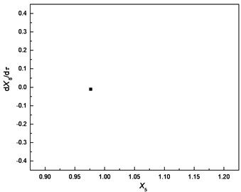
Fig. 6Comparison of responses of cutter tip under different bearing clearances: a), b), c) δ=0; d), e), f) δ=0.5e; g), h), i) δ=e; j), k), l) δ=5e
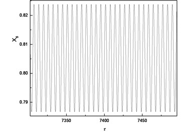
a) Time-domain response
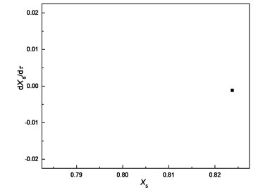
b) Poincare section
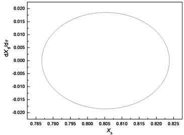
c) Phase trajectory
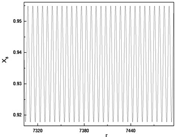
d) Time-domain response
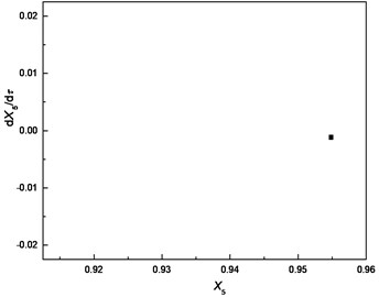
e) Poincare section
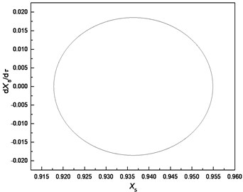
f) Phase trajectory
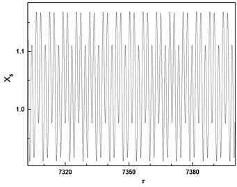
g) Time-domain response
h) Poincare section
i) Phase trajectory
j) Time-domain response
k) Poincare section
l) Phase trajectory
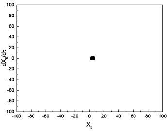
The comparison highlights that each Poincare section under different bearing clearances is a single point; therefore, the responses of cutter tip under different bearing clearances are all periodic motions. The dimensionless displacement of cutter tip ranges [0.787, 0.824] when . It ranges [0.918, 0.955] when and it ranges [1.003, 1.081] when The equilibrium position varies with the increase of bearing clearance. It can be concluded that the bearing clearance mainly has effects on equilibrium position of vibration, and a greater bearing clearance leads to more serious deviation of the equilibrium position from its original position.
When , bearing clearance changes not only the equilibrium position but also the vibration mode of cutter tip. Although the vibration is still a periodic motion, three peaks occur in a period.
To investigate the effects of clearance on the motion of cutter tip, the dimensionless bearing clearance and frequency ratio are introduced to obtain the bifurcation diagram, where is the critical rotation speed of the system. In the process of numerical simulation, the cutting force is not considered. The numerical results with 0.8 is shown in Fig. 7. The dimensionless bearing clearance is chosen as the control parameter to generate the bifurcation diagram, which is depicted in Fig. 7(a). From the bifurcation diagram, it is concluded that the motion of cutter tip is a periodic orbit in the range [0.6, 1.3], which is confirmed by the result in Fig. 7(b). With the increasing of the bearing clearance, the response of cutter tip is chaotic in the range [1.35, 1.5]. Poincare section with 1.45 is shown in Fig. 7(c), which can confirm this response is chaotic. As the bearing clearance increases further, the response regains a periodic orbit in the range [1.55, 1.6]. This conclusion can be confirmed by Poincare section depicted in Fig. 7(d). As increases beyond 1.65, the response of cutter tip becomes chaotic again, which is confirmed by the result in Fig. 7(e).
Fig. 7Nonlinear dynamics of cutter tip with η= 0.8
a) Bifurcation diagram
b) Poincare section with 0.7
c) Poincare section with 1.45
d) Poincare section with 1.55
e) Poincare section with 3
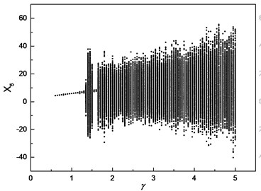
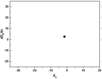
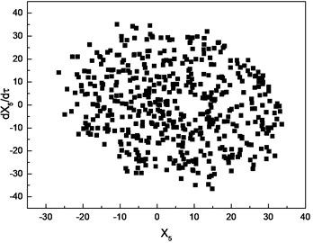
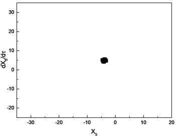
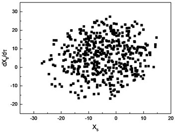
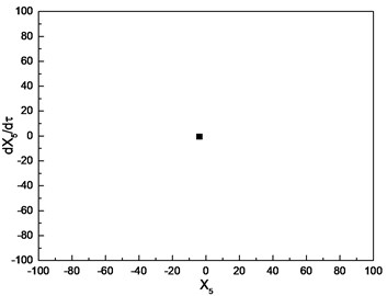
Similar investigation is conducted with 1.0. The numerical results are depicted in Fig. 8. The parameter is chosen as the control parameter to generate the bifurcation diagram, which is shown in Fig. 8(a). From the diagram, the conclusion can be drawn that the motion of cutter tip is a periodic orbit in the range [0.01, 0.31], which is confirmed by Poincare section depicted in Fig. 8(b). As the increasing of , the response of cutter tip develops into a quasi-periodic orbit. Poincare section depicted in Fig. 8(c)-(e) can confirm the conclusion. As increases beyond 3.61, the response of cutter tip becomes a periodic orbit again, which is confirmed by Poincare section shown in Fig. 8(f).
From Fig. 7 and Fig. 8, it is concluded that the responses of cutter tip exhibit periodic, quasi-periodic and chaotic characteristics with different values of bearing clearance and rotation speed. The dynamic characteristic of spindle-cutter system strongly depends on the bearing clearance and rotation speed. Therefore, the proper bearing clearance and rotation speed should be chosen to ensure a stable cutting and high cutting rate according to the bifurcation diagram.
Fig. 8Nonlinear dynamics of cutter tip with η= 1.0
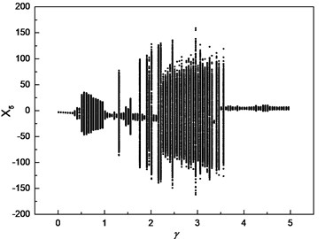
a) Bifurcation diagram
b) Poincare section with 0.16
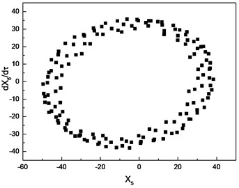
c) Poincare section with 0.6
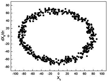
d) Poincare section with 1.6
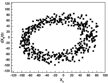
e) Poincare section with 3.2
f) Poincare section with 4
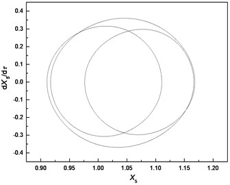
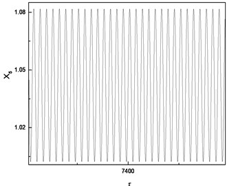
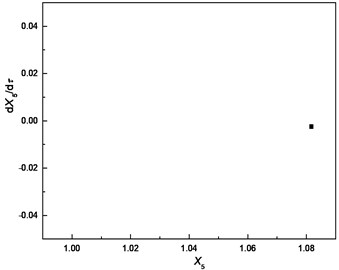
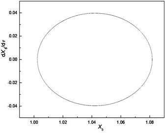
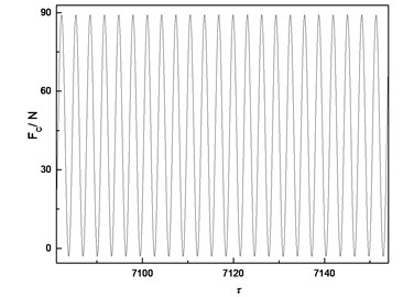
According to Fig. 9, the response of the cutter tip is similar to a periodic motion when the cutting force is considered. The amplitude of time-domain response is in a certain range; the phase trajectory is a curve with a certain width. The time-domain response of cutter tip predicted by nonlinear dynamic analysis can provide the basis for the machining error prediction. The dynamic radial cutting force during milling can be predicted by numerical simulation, which is shown in Fig. 10.
Fig. 9Response of cutter tip considering cutting force

a) Time-domain response
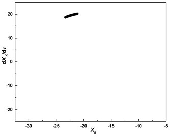
b) Poincare section
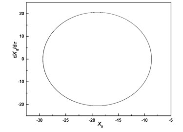
c) Phase trajectory
Fig. 10Radial cutting force
7. Conclusions
A nonlinear dynamic model of spindle-cutter coupling system under cutting force, which takes into account the stiffness of cutter and the nonlinearity of bearing clearance, is established in this research. The model of cutting force takes into account the displacement of cutter tip by accumulating it into the cutting width. The results of the numerical simulations indicate that the bearing clearance mainly affects the equilibrium position of vibration. A greater bearing clearance leads to a more serious deviation of the equilibrium position from its original position. With different values of bearing clearance and rotation speed, the responses of cutter tip exhibit periodic, quasi-periodic and chaotic characteristics. Dynamic characteristics of spindle-cutter system strongly depends on the bearing clearance and rotation speed. The proper bearing clearance and rotation speed should be chosen to ensure a stable cutting and high cutting rate according to the bifurcation diagram. The response of the cutter tip is a quasi-periodic motion when the cutting force is considered. The time-domain response of cutter tip predicted by nonlinear dynamic analysis can provide the basis for machining error prediction.
References
-
Yu T., Wang X., Wang W. Numerical analysis of dynamic characteristics in the ultra-high speed grinding spindle system. Journal of Vibroengineering, Vol. 17, Issue 7, 2015, p. 3483-3494.
-
Zhang W., Gao W., Long X., et al. Nonlinear analysis for a machine-tool spindle system supported with ball screw. Journal of Vibration and Shock, Vol. 27, Issue 9, 2008, p. 72-183.
-
Gao S., Meng G. Unstable islands and bifurcation analysis in a spindle milling system supported by ball bearings. Proceedings of the Institution of Mechanical Engineers, Part K: Journal of Multi-body Dynamics, Vol. 225, Issue 8, 2011, p. 235-251.
-
Gao S., Meng G., Li H., et al. Non-linear dynamics of an unbalanced machine-tool spindle system supported by ball bearings. Proceedings of the Institution of Mechanical Engineers, Part K: Journal of Multi-body Dynamics, Vol. 222, Issue 3, 2008, p. 201-214.
-
Gao S., Long X., Meng G. Nonlinear response and stability of a spindle system supported by ball bearings. Archive of Applied Mechanics, Vol. 80, Issue 9, 2010, p. 1069-1081.
-
Gao S., Nong S., Xu W., et al. The nonlinear vibration and stability of a non-uniform continuous spindle system with nonlinear and nonsmooth boundaries. Journal of Vibration and Control, Vol. 22, Issue 5, 2016, p. 1392-1404.
-
Zhang Z., Li A., Liu X., et al. Nonlinear modeling and numerical simulation of high speed spindle system. Journal of Vibration, Measurement and Diagnosis, Vol. 34, Issue 5, 2014, p. 878-977.
-
Si Z., Ma W., Li J., et al. Analysis of the vibration characteristic of rolling bearing-rotor system of machine tool spindle. Journal of Mechanical Transmission, Vol. 39, Issue 9, 2015, p. 121-125.
-
Zhao W., Li J., Yu G. Simulation on gyration accuracy of precision machine tool spindle considering nonlinear dynamic effect. Journal of Henan Polytechnic University (Natural Science), Vol. 31, Issue 1, 2012, p. 72-77.
-
Lioulios A., Antoniadis I. Effect of rotational speed fluctuations on the dynamic behavior of rolling element bearings with radial clearances. International Journal of Mechanical Sciences, Vol. 48, Issue 8, 2006, p. 809-829.
-
Gao X., Zhang Y., Wu Q. Dynamic optimization of the spindle-cutter coupling system. Applied Mechanics and Materials, Vol. 42, 2011, p. 17-21.
-
Gao X., Zhang Y., Zhang H. Modeling approach for interface stiffness of spindle-tool holder. Computer Integrated Manufacturing Systems, Vol. 19, Issue 1, 2013, p. 61-66.
-
Wen B., Liu S., Chen Z., et al. Theory of Mechanical Vibration and its Applications. First Edition, Higher Education Press, Beijing, 2009.
-
Kim G., Kim B., Chu C. Estimation of cutter deflection and form error in ball-end milling processes. International Journal of Machine Tools and Manufacture, Vol. 43, Issue 9, 2003, p. 917-924.
-
Shirase K., Altintas Y. Cutting force and dimensional surface error generation in peripheral milling with variable pitch helical end mills. International Journal of Machine Tools and Manufacture, Vol. 36, Issue 5, 1996, p. 567-584.
-
Salgado M., Lacalle L., Lamikiz A., et al. Evaluation of the stiffness chain on the deflection of end-mills under cutting forces. International Journal of Machine Tools and Manufacture, Vol. 45, Issue 6, 2005, p. 727-739.
-
Xu A., Qu Y., Zhang D., et al. Simulation and experimental investigation of the end milling process considering the cutter flexibility. International Journal of Machine Tools and Manufacture, Vol. 43, Issue 3, 2003, p. 283-292.
-
Ong T., Hinds B. The application of tool deflection knowledge in process planning to meet geometric tolerances. International Journal of Machine Tools and Manufacture, Vol. 43, Issue 7, 2003, p. 731-737.
-
Ryu S., Lee H., Chu C. The form error prediction in side wall machining considering tool deflection. International Journal of Machine Tools and Manufacture, Vol. 43, Issue 14, 2003, p. 1405-1411.
-
Li Z. Dynamic Modeling, Simulation and Optimization of High Speed Milling under Complicated Cutting Conditions. Beihang University, Beijing, 2008.
-
Hibbeler R. Mechanics of Materials. Fifth Edition (Photocopied), Higher Education Press, Beijing, 2004.
-
Wang M., Li F., Zan T., et al. Bending vibration control of a ball screw via multi-tuned mass dampers. Journal of Vibration and Shock, Vol. 34, Issue 10, 2015, p. 63-67.
-
Altintas Y. Manufacturing Automation. Cambridge University Press, Cambridge, 2000.
-
Wu Q., Zhang Y., Zhang H. Corner-milling of thin walled cavities on aeronautical components. Chinese Journal of Aeronautics, Vol. 22, Issue 6, 2009, p. 677-684.
About this article

This work is supported by National Natural Science Foundation of China, Grant No. 51505012 and 51575014; Natural Science Foundation of Beijing, Grant No. 3154029 and KZ201410005010; Important National Science and Technology Specific Projects of China, Grant No. 2012ZX04010021-001-004; China Postdoctoral Science Foundation Funded Project, Grant No. 2016M591033; and Beijing Postdoctoral Research Foundation, Grant No. 2015ZZ-13. The authors are grateful to the other participants in the projects for their cooperation.
