Abstract
The dynamic characteristics of a high-contact-ratio (HCR) spur-gear system having rough surfaces generated by shot peening (SP) were studied, with specific emphasis on characterisation of the gear-surface topography as well as modelling of the gear backlash and static transmission error. Accordingly, a four-degree-of-freedom dynamic model was established. Simulation experiments were then conducted using surface roughness, rotational velocity, input torque, and shaft-bearing stiffness as the variables. The results show that the dynamic characteristics of the gear system tend toward instability with increasing surface roughness. The models developed in this study outline a method for building indirect relationships between the vibration, dynamics, and tooth-surface microscopic features. This research thus provides a theoretical basis for designing the tooth-surface topography of HCR gears in the future.
1. Introduction
The rapid growth and development of the manufacturing industry has promoted the need for gear systems in various domains, such as aerospace, robots, and vehicles, with demand for high bearing capacities and lengthy service lifetimes. High-contact-ratio (HCR) spur gears are defined as gears whose contact ratios are greater than two [1]. The mesh stiffness of the HCR spur gear is much larger than that of the low-contact-ratio (LCR) spur gear [2] when all the other parameters are equal; therefore, HCR spur gears are widely used in the abovementioned fields [3]. In addition, high-performance gears must demonstrate low vibration and noise, especially for Noise, Vibration and Harshness (NVH) performance optimisation in battery-powered electric vehicles. The dynamic characteristics of gears influence their vibrations considerably. Research on gear dynamics have been reported in literature extensively [4-11]. Yang [12] adopted a multi-scale method to study gear-system stability. Xiang [13] researched the effects of oil-film stiffness on spur-gear dynamics. Ouyang [14] studied the lubricating and dynamic performances of high-speed spur gears. Pan [15] investigated the gear dynamic behaviours under the effects of tooth-contact temperature and random excitations. However, most of these studies involved LCR gear systems.
The meshing surfaces of gears constitute a type of sportive joint surface, where the surface contact pressures are limited within a certain range. There may also be geometric shape errors and microscopic irregularities on the contact surfaces and in various media. Different machining techniques often produce surface-feature differences. Shot peening (SP) can improve the fatigue properties of metallic components exposed to cyclic loadings [16], so this method is widely used in gear-surface treatments [17-19]. During the SP process, numerous high-speed shots impact a given surface to modify its morphology, refine the grain [20], and promote phase transformation [21]. Surface morphology changes often have positive effects on the mechanical properties of the treated gears; however, they may also produce negative effects that make the gears more prone to unexpected faults. Previous studies on gear SP primarily investigated the relationships among the process parameters, residual stresses, roughnesses, corrosion behaviours, and fatigue properties [22-25]. However, none of the reported studies focused on the dynamic behaviours of HCR gear systems by considering the rough surfaces generated by SP. Many researchers have focused on characterising machined rough surfaces using fractal theory [26-27]. In the study of gear dynamics, the gear teeth are often regarded as cantilever beams. In terms of beam dynamics, Pankaj Charan Jena et al. considered the effects of cracks, vibration characteristics, bidirectional fibre-angle changes, and other factors [28-31]. In addition, the Timoshenko beam theory, higher-order shear-deformation theory, and higher-order stratification theory are widely used in beam vibration and dynamics analyses [32-36]. However, these studies have some disadvantages as follows. First, the static transfer error calculation is based on a smooth surface that neglects the effects of surface roughness. Second, the dynamic characteristics of HCR spur gears having rough surfaces are seldom considered. Solving the above deficiencies is the main contribution of this study.
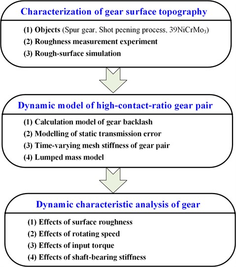
Therefore, the dynamic behaviours of HCR gear systems with rough surfaces generated by SP are discussed in this work in terms of backlash and transmission errors. Fig. 1 depicts a flow chart of the simulations performed in this study. The remainder of this paper is organised as follows: Section 2 presents the gear-surface topography characterisation. Section 3 illustrates the proposed dynamic model. Section 4 presents analyses of the dynamic behaviours of the system under multiple non-linear parameters. Section 5 presents the main conclusions of this study.
Fig. 1Flow chart of the simulations in this study
2. Characterisation of gear-surface topography
2.1. Roughness measurement experiment
SP is typically used as the final step in the gear manufacturing process, before which machining trace lines are produced on the gear surfaces by the preceding procedures. During SP, many high-speed shots impact the gear surfaces randomly to produce regular craters. With increasing coverage from these shots, the craters overlap and influence each other, thereby changing the micro-morphology of the gear surfaces completely. After SP, the original machining traces on the surface disappear. Different SP processes produce dissimilar surface topographies; however, improper process parameters may cause surface cracking, folding, broken projectile embedment on the surface, and fatigue resistance reduction of the metal parts [37]. 39NiCrMo3 is a type of low-alloy steel that is widely used to produce gears owing to its resistance to thermal cracking [38]. In the present study, 39NiCrMo3 was chosen to manufacture HCR gears by wire cutting, and the gears were subsequently subjected to SP treatment.
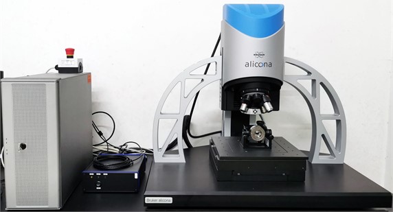
Aroughsurfaceiscomposedofharmoniccomponentswithseveralfrequenciesandmaybedescribedbyitscorrespondingroughnessparameters.Thesurfacetopographyofanobject is described by its surface profile; herein, the surface profiles and corresponding roughness parameters were directly tested using a three-dimensional measurement system (Alicona Infinite focus G5), as shown in Fig. 2. Among the parameters used to quantify the surface roughness , the arithmetic mean deviation of the assessed profile defined by Eq. (1) is the most widely used parameter [39]:
where represents the peak heights within a sampling length . The test results in this study indicate that the roughness parameter of the tooth surfaces of the SP-treated gears changed from 0.59 μm to 5.13 μm.
Fig. 2Three-dimensional measurement equipment
2.2. Rough-surface simulation
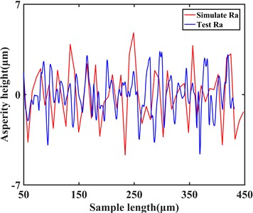
Based on previous reports, a machined surface has fractal characteristics that can be described using a formula, and the Weierstrass- Mandelbrot (W-M) function is suitable for characterising the rough surface [40-41]. The height of the random asperity of the gear-tooth profile based on the W-M function is expressed as follows:
where, denotes the fractal dimension, is the discrete frequency spectrum of the surface roughness, is the lower cut-off frequency of the profile, and is the characteristic scale coefficient [1]. Therefore, the measured surface profile of a gear can be approximately simulated by selecting appropriate fractal parameters, as shown in Fig. 3.
Fig. 3Two-dimensional gear-surface profile with Ra= 1.13 μm
3. Dynamic model
3.1. Gear backlash and static transmission error
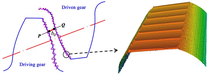
A meshing gear pair with rough surfaces is shown in Fig. 4, where is the highest point among the tooth asperities in the driving gear, and is the highest point among the tooth asperities in the driven gear; is the initial backlash; is the real surface roughness; is a function to obtain the corresponding with a definite , which can be obtained from an extant work [27]. According to another report [42], the new height of the surface asperities can be defined as:
The actual tooth topography and tooth-profile deviation can be simulated and calculated using Eq. (3). Considering the differences between the roughnesses of two teeth and their fractal dimensions, gear backlash can be redefined as follows [42]:
where, is the time-varying backlash of the gear pair; and denote the measured surface roughness values of the driving and driven gears, respectively; is the characteristic scale coefficient (set as 1.5 according to [43]); and denote the measured fractal dimensions of the driving and driven gears, respectively.
Fig. 4Illustration of gear backlash with tooth-surface microscopic features
The deviation between the real profile of the gear surface and a perfect surface is the main cause of the static transmission error. As noted above, the tooth profile may be uneven after SP. Here, is expressed as the static transmission error, which may be regarded as the synthesised tooth-profile micro-deviation of each tooth given a teeth pair, ignoring the effects of spacing and run-out errors. Therefore, according to Eq. (3), the static transmission error considering rough surfaces can be expressed as follows:
3.2. Mesh stiffness
The numbers of teeth engaged during the meshing process may vary. An analytical method, a finite-element method, and an analytical-finite-element approach are commonly used to solve the mesh stiffness [44]. As shown in Fig. 5, Ma [45] proposed an improved potential energy method to calculate the mesh stiffness, which was validated by the finite-element method. Therefore, the potential-energy method proposed by Ma is adopted in the present work and expressed as follows:
where the subscripts 1 and 2 represent the driving and driven gears of the tooth pair, respectively. Based on previous research [46], the single-tooth-pair mesh stiffness is defined as follows:
Fig. 5Geometric model of a gear profile [45]
![Geometric model of a gear profile [45]](https://static-01.extrica.com/articles/23330/23330-img5.jpg)
The stiffness for a single pair of teeth making and breaking contact can be solved using a computer program and then fitted to the form of the Fourier function as follows:
where is the average mesh stiffness; and are the amplitudes of the -th order harmonics; is a fitting frequency of the Fourier series with the fitting period being equal to the mesh period. The stiffness excitation period can be deduced as . Generally, a good fit can be achieved with the first six orders of the fourier series. Based on results calculated using the potential-energy method, the fitting parameters are presented in Table 1.
Table 1Coefficients of the harmonic components (N/m)
1 | –1.003e+07 | 1.233e+08 |
2 | 1.757e+07 | 2.923e+06 |
3 | 2.393e+06 | –9.463e+06 |
4 | –3.053e+06 | –1.055e+06 |
5 | –3.234e+05 | 7.274e+05 |
6 | 9.327e+04 | 5.15e+04 |
km | 3.8925e+08 |
Then, the time-varying mesh stiffness can be calculated by defining three teeth pairs in the mesh. Ignoring the effects between the teeth, the piecewise mesh-stiffness functions of the three teeth pairs are expressed as follows:
At last, the time-varying mesh stiffness of the HCR gear system can be calculated using Eqs. (7)-(12), whose results are displayed in Fig. 6:
3.3. Dynamic equation
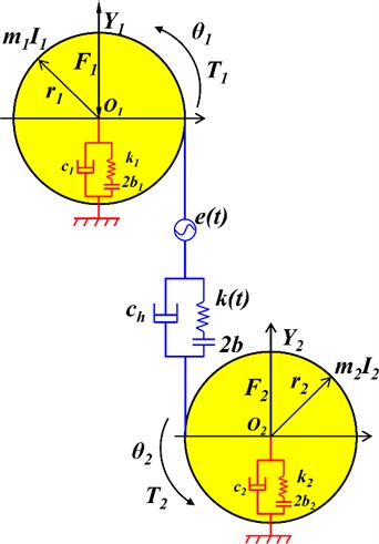
The HCR gear system is mainly composed of gears, shafts, and bearings. The non-linear dynamic model of this gear system is shown in Fig. 7, where and are the torques impacting the driving and driven gears, and and are the external radial pre-loads sustained by the corresponding bearings, respectively. Further, is the mass moment of inertia, is the mass, is the equivalent support damping, is the damping coefficient of the gear mesh, is the radius of the base circle, is the equivalent support stiffness of the bearing, and is the mesh direction. The essential dynamics of the gear system can be described as a four-degrees-of-freedom system with coordinates , where and are the dynamic angular displacements of gears 1 and 2, and and are the displacements of the corresponding bearings, respectively. The quantities and refer to the bearing clearance and gear meshing backlash, respectively. As a new relative coordinate, y is defined as transmission error (TE), as follows:
Fig. 6Curves of mesh stiffness with respect to mesh cycle
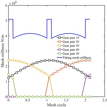
Fig. 7Dynamic model of the HCR gear-transmission system
The dynamic differential equation of the gear system can now be derived using Newton’s second law of motion as follows:
where ( 1, 2) is the radial clearance displacement function of the bearing along the direction, which can be expressed as:
and is a piecewise backlash function described as follows:
Then, the dynamic differential equations can be transformed as follows:
where is the equivalent mass of the HCR gear system, and is the average force related to the mean torque. Additionally, the dynamic meshing force (DMF) can be deduced as follows:
4. Results and discussion
Eq. (17) illustrates a series of dynamic equations. In this study, the solutions of these coupled non-linear equations are solved using the Runge-Kutta numerical method. The main parameters of the HCR gear system are listed in Table 2. As a gear pair rotates in the mesh, the TE is the main excitation that dictates the line-of-action (LOA) vibrational motion [47]. It is therefore necessary to choose suitable parameters for assessing the motion state of the HCR gear system to reduce vibrations and avoid chaos. To understand the dynamic features of the system comprehensively, the surface roughness, rotating speed, input torque, and shaft-bearing stiffness were selected as the control parameters.
Table 2Main parameters of the HCR gear system
Parameters | Pinion/Gear | Parameters | Pinion/Gear |
Material | 39NiCrMo3 | Elasticity modulus (GPa) | 190 |
Number of teeth / | 45 | Addendum coefficient | 1.3 |
Transverse modulus (mm) | 3 | Poisson ratio | 0.3 |
Mass (kg) m1/m2 | 1.914 | Pressure angle (°) | 20 |
Moment of inertia (kg·m2) / | 0.003 | Initial backlash (μm) | 10 |
Bearing stiffness (N/m) / | 1e8 | Initial mesh damping ratio | 0.043 |
Bearing clearance (μm) / | 10 | /(N) | 0 |
Tooth width (mm) | 25 | Hub-core radius (mm) | 13.5 |
4.1. Effects of surface roughness
To study the surface roughness effects on the system responses, the parameter was selected as the variable in the corresponding time-history chart, phase diagram, Poincare map, and time response of the DMF. The other system parameters used in the numerical simulations are as follows: 1500 r/min; , 1.1; 500 N·m. Thus, Fig. 8 illustrates the dynamic responses for different surface roughness values.
Fig. 8System responses of the transmission errors and dynamic meshing forces for varying surface roughnesses: a) time-history chart; b) phase diagram; c) Poincare map; d) DMF curve
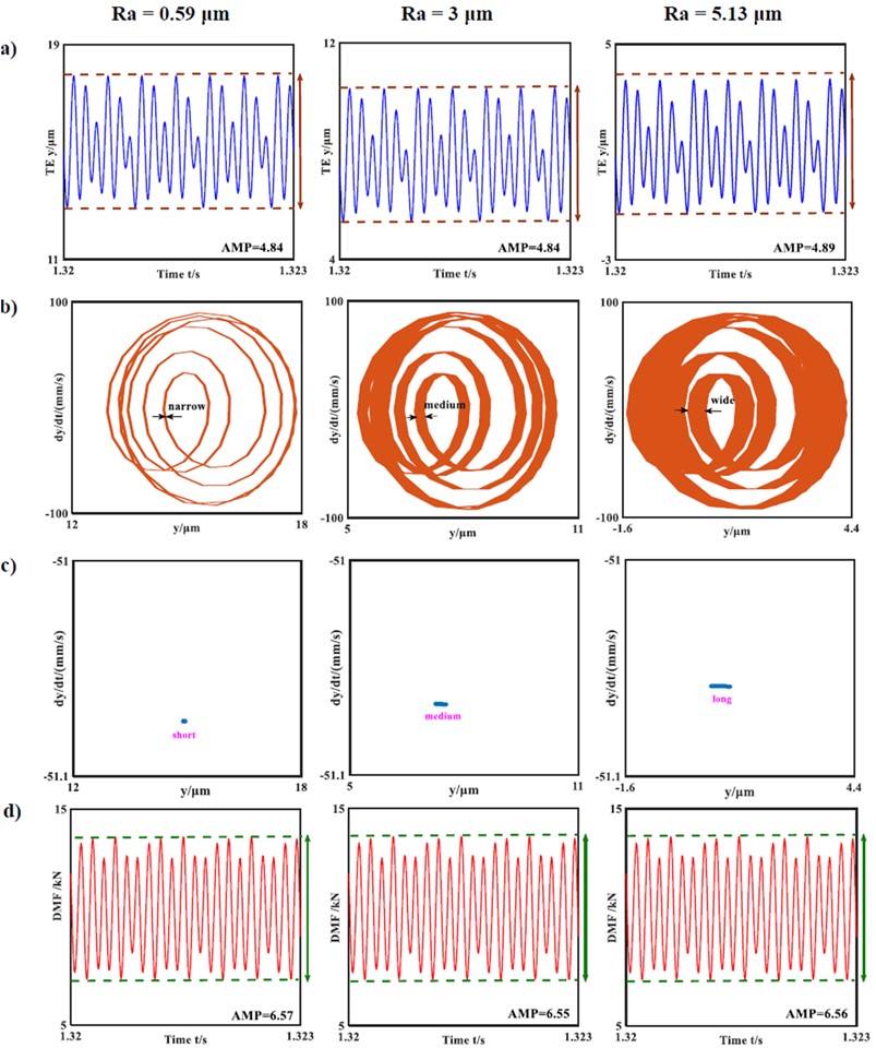
Based on the simulation results, the system dynamic responses are generally divided into simple harmonic, non-harmonic single periodic, sub-harmonic, quasi-periodic, and chaotic responses. From Fig. 8, it is clear that the HCR gear system is under the non-harmonic single periodic response state when 0.59 μm. As shown in Fig. 8(b), the phase graph is a non-circular and non-elliptical curve, and the Poincare map is a dot. Here, AMP represents the amplitude of displacement or force. From the experimental results, the changes in the gear dynamic responses with respect to are tracked. As the magnitude of increases from 0.59 μm to 5.13 μm, the vibration and DMF amplitudes change slightly, except for the curve widths in the phase diagram and point distribution on the Poincare map. As the surface roughness increases, the phase-diagram curve widths increase gradually, and the point distribution on the Poincare map becomes more disorderly, as can be seen in Figs. 8(b) and 8(c).
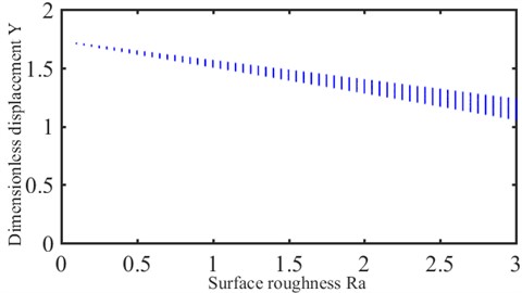
This phenomenon indicates that the system state changes from single-period to quasi-periodic motions with increasing roughness. More broadly, as shown in Fig. 9, the variations in the bifurcation diagram show that the dynamic responses of the HCR gear system tend from stable toward unstable motions. Therefore, it is concluded that the dynamic characteristics of the HCR gear system are influenced by SP, where the increase in produced by SP causes the gear dynamics to tend toward instability.
Fig. 9Bifurcation diagram with respect to surface roughness
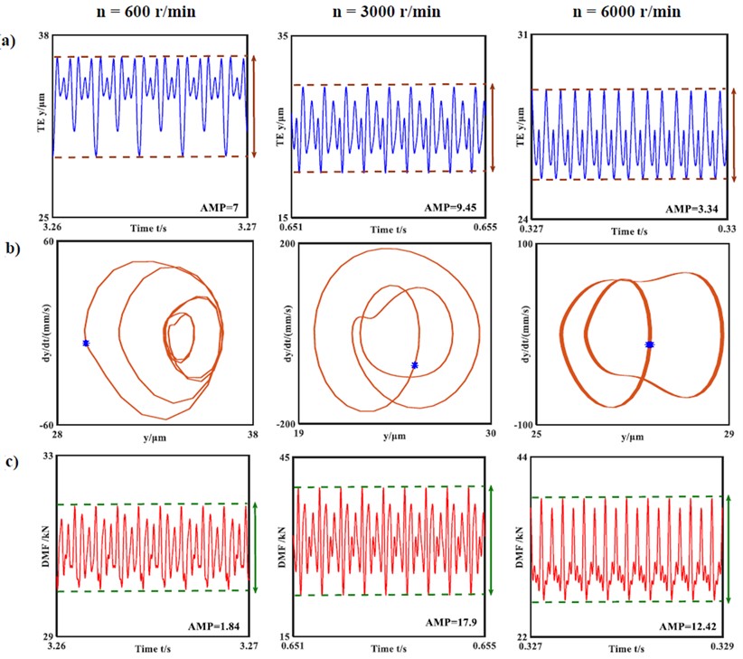
4.2. Effects of rotating speed
The rotating speed of the pinion is commonly used as a regulating parameter to study the non-linear dynamic characteristics of a gear transmission system. For enhanced practical engineering value, different rotating speeds are simulated to investigate their influences on the dynamic responses. The HCR spur gears are generally used under heavy loading conditions. Therefore, the load torque is set to 1500 N·m, and the other system parameters are set as follows: , 1.1; 1.51 μm. Fig. 10 depicts the simulated system responses at low, medium, and high rotating speeds. The HCR gear system is under the non-harmonic single periodic response state for all three speed conditions. The response periods of the time-history charts are equal to the excitation periods. With increase in rotating speed, the amplitude of the transmission error increases first and then decreases. Simultaneously, the DMF amplitude varies similarly; the degree of fluctuation of the DMF is significantly enhanced with increasing rotating speeds and decreases later.
4.3. Effects of input torque
The input torque plays a critical role in the dynamic behaviour, and the system parameters used in the numerical simulations are as follows: 2000 r/min; , 1.1; 1.51 μm. As seen in Fig. 11, all systems demonstrate non-harmonic single periodic responses, and the phase diagrams are non-elliptical curves. The shapes of all phase diagrams are similar, but the results indicate that increases in the input torques, transmission errors, and DMFs are accompanied by increasing amplitudes. In addition, the ranges of the phase curves are expanded.
Fig. 10System responses of the transmission errors and dynamic meshing forces for varying rotating speeds: a) time-history chart; b) phase diagram and Poincare map; c) DMF curve
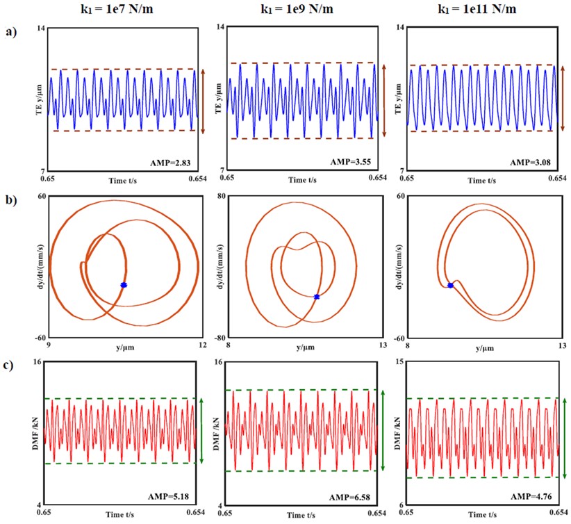
4.4. Effects of shaft-bearing stiffness
To understand the effects of the shaft-bearing stiffness, is selected as the variable in the corresponding dynamic system response. The other system parameters used in the numerical simulations are as follows: 500 N·m; 3000 r/min; , 1.1; 1.51 μm. The shaft-bearing stiffness value is varied from 1e7 N/m to 1e11 N/m, and the results indicate that the bearing support state changes from elastic to rigid supports. It is obvious that the shaft-bearing stiffness influences the dynamic characteristics. As shown in Fig. 12, the HCR gear system is under the non-harmonic single periodic response state for different shaft-bearing stiffness conditions, and the phase diagram is a non-circular and non-elliptical curve. Moreover, each Poincare map shows a set of centralised points. The amplitudes of the transmission errors and DMF curves increase first and then decrease as the shaft-bearing stiffness improves. However, the minimum DMF amplitude is always greater than zero in all the numerical experiments. Thus, the non-impact state of the HCR gear system can be further verified.
Fig. 11System responses of the transmission errors and dynamic meshing forces for varying input torques: a) time-history chart; b) phase diagram and Poincare map; c) DMF curve
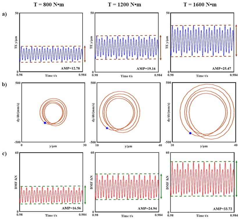
Fig. 12System responses of the transmission errors and dynamic meshing forces for varying shaft-bearing stiffness values: a) time-history chart; b) phase diagram and Poincare map; c) DMF curve
5. Conclusions
This study focuses mainly on the dynamic responses of the HCR gear system by considering the effects of rough surfaces produced through SP. The main conclusions of the study are summarised as follows:
1) As the surface roughness increases, the dynamic characteristics of the gear system tend toward instability.
2) The minimum DMF is always greater than zero, indicating that the gear system is always in the non-impact state.
The next step in our research is to try to study the effects of the shot peening parameters on gear dynamics.
References
-
K. Huang, Y. Xiong, T. Wang, and Q. Chen, “Research on the dynamic response of high-contact-ratio spur gears influenced by surface roughness under EHL condition,” Applied Surface Science, Vol. 392, pp. 8–18, Jan. 2017, https://doi.org/10.1016/j.apsusc.2016.09.009
-
S. M. Wang and M. G. Ji, “Study on the best profile modification of high-speed spur gears with high-contact-ratio,” Acta Aeronautica et Astronautica Sinica, Vol. 17, pp. 119–122, 1996.
-
S. Li, “Effect of addendum on contact strength, bending strength and basic performance parameters of a pair of spur gears,” Mechanism and Machine Theory, Vol. 43, No. 12, pp. 1557–1584, Dec. 2008, https://doi.org/10.1016/j.mechmachtheory.2007.12.010
-
C. Siyu, T. Jinyuan, L. Caiwang, and W. Qibo, “Nonlinear dynamic characteristics of geared rotor bearing systems with dynamic backlash and friction,” Mechanism and Machine Theory, Vol. 46, No. 4, pp. 466–478, Apr. 2011, https://doi.org/10.1016/j.mechmachtheory.2010.11.016
-
L. Xiang, Y. Jia, and A. Hu, “Bifurcation and chaos analysis for multi-freedom gear-bearing system with time-varying stiffness,” Applied Mathematical Modelling, Vol. 40, No. 23-24, pp. 10506–10520, Dec. 2016, https://doi.org/10.1016/j.apm.2016.07.016
-
Z. Li and Z. Peng, “Nonlinear dynamic response of a multi-degree of freedom gear system dynamic model coupled with tooth surface characters: a case study on coal cutters,” Nonlinear Dynamics, Vol. 84, No. 1, pp. 271–286, Apr. 2016, https://doi.org/10.1007/s11071-015-2475-5
-
J. Wang, G. He, J. Zhang, Y. Zhao, and Y. Yao, “Nonlinear dynamics analysis of the spur gear system for railway locomotive,” Mechanical Systems and Signal Processing, Vol. 85, pp. 41–55, Feb. 2017, https://doi.org/10.1016/j.ymssp.2016.08.004
-
S. Zhou, Z. Ren, G. Song, and B. Wen, “Dynamic characteristics analysis of the coupled lateral-torsional vibration with spur gear system,” International Journal of Rotating Machinery, Vol. 2015, pp. 1–14, 2015, https://doi.org/10.1155/2015/371408
-
H. Liu, C. Zhang, C. L. Xiang, and C. Wang, “Tooth profile modification based on lateral – torsional-rocking coupled nonlinear dynamic model of gear system,” Mechanism and Machine Theory, Vol. 105, pp. 606–619, Nov. 2016, https://doi.org/10.1016/j.mechmachtheory.2016.07.013
-
W. Guangjian, C. Lin, Y. Li, and Z. Shuaidong, “Research on the dynamic transmission error of a spur gear pair with eccentricities by finite element method,” Mechanism and Machine Theory, Vol. 109, pp. 1–13, Mar. 2017, https://doi.org/10.1016/j.mechmachtheory.2016.11.006
-
Z. Cao, Y. Shao, M. Rao, and W. Yu, “Effects of the gear eccentricities on the dynamic performance of a planetary gear set,” Nonlinear Dynamics, Vol. 91, No. 1, pp. 1–15, Jan. 2018, https://doi.org/10.1007/s11071-017-3738-0
-
Y. Yang, L. Cao, H. Li, and Y. Dai, “Nonlinear dynamic response of a spur gear pair based on the modeling of periodic mesh stiffness and static transmission error,” Applied Mathematical Modelling, Vol. 72, pp. 444–469, Aug. 2019, https://doi.org/10.1016/j.apm.2019.03.026
-
Z. Xiao, C. Zhou, S. Chen, and Z. Li, “Effects of oil film stiffness and damping on spur gear dynamics,” Nonlinear Dynamics, Vol. 96, No. 1, pp. 145–159, Apr. 2019, https://doi.org/10.1007/s11071-019-04780-6
-
T. Ouyang, G. Huang, J. Chen, B. Gao, and N. Chen, “Investigation of lubricating and dynamic performances for high-speed spur gear based on tribo-dynamic theory,” Tribology International, Vol. 136, pp. 421–431, Aug. 2019, https://doi.org/10.1016/j.triboint.2019.03.009
-
W. Pan, X. Li, L. Wang, and Z. Yang, “Nonlinear response analysis of gear-shaft-bearing system considering tooth contact temperature and random excitations,” Applied Mathematical Modelling, Vol. 68, pp. 113–136, Apr. 2019, https://doi.org/10.1016/j.apm.2018.10.022
-
S.-J. Yoon, J.-H. Park, and N.-S. Choi, “Fatigue life analysis of shot-peened bearing steel,” Journal of Mechanical Science and Technology, Vol. 26, No. 6, pp. 1747–1752, Jun. 2012, https://doi.org/10.1007/s12206-012-0340-8
-
M. Benedetti, “Influence of shot peening on bending tooth fatigue limit of case hardened gears,” International Journal of Fatigue, Vol. 24, No. 11, pp. 1127–1136, Nov. 2002, https://doi.org/10.1016/s0142-1123(02)00034-8
-
E. Nordin and B. Alfredsson, “Experimental investigation of shot peening on case hardened SS2506 gear steel,” Experimental Techniques, Vol. 41, No. 4, pp. 433–451, Aug. 2017, https://doi.org/10.1007/s40799-017-0183-4
-
A. Zammit, M. Bonnici, M. Mhaede, R. Wan, and L. Wagner, “Shot peening of austempered ductile iron gears,” Surface Engineering, Vol. 33, No. 9, pp. 679–686, Sep. 2017, https://doi.org/10.1080/02670844.2016.1266118
-
O. Unal and R. Varol, “Surface severe plastic deformation of AISI 304 via conventional shot peening, severe shot peening and repeening,” Applied Surface Science, Vol. 351, pp. 289–295, Oct. 2015, https://doi.org/10.1016/j.apsusc.2015.05.093
-
J. L. Liu, M. Umemoto, Y. Todaka, and K. Tsuchiya, “Formation of a nanocrystalline surface layer on steels by air blast shot peening,” Journal of Materials Science, Vol. 42, No. 18, pp. 7716–7720, Sep. 2007, https://doi.org/10.1007/s10853-007-1659-x
-
K. Takahashi, H. Osedo, T. Suzuki, and S. Fukuda, “Fatigue strength improvement of an aluminum alloy with a crack-like surface defect using shot peening and cavitation peening,” Engineering Fracture Mechanics, Vol. 193, pp. 151–161, Apr. 2018, https://doi.org/10.1016/j.engfracmech.2018.02.013
-
H. Kovacı, Y. B. Bozkurt, A. F. Yetim, M. Aslan, and A. Çelik, “The effect of surface plastic deformation produced by shot peening on corrosion behavior of a low-alloy steel,” Surface and Coatings Technology, Vol. 360, pp. 78–86, Feb. 2019, https://doi.org/10.1016/j.surfcoat.2019.01.003
-
H. Soyama, “Comparison between the improvements made to the fatigue strength of stainless steel by cavitation peening, water jet peening, shot peening and laser peening,” Journal of Materials Processing Technology, Vol. 269, pp. 65–78, Jul. 2019, https://doi.org/10.1016/j.jmatprotec.2019.01.030
-
L. R. Krishna, Y. Madhavi, T. Sahithi, N. P. Wasekar, N. M. Chavan, and D. S. Rao, “Influence of prior shot peening variables on the fatigue life of micro arc oxidation coated 6061-T6 Al alloy,” International Journal of Fatigue, Vol. 106, pp. 165–174, Jan. 2018, https://doi.org/10.1016/j.ijfatigue.2017.09.020
-
Q. Chen, F. Xu, P. Liu, and H. Fan, “Research on fractal model of normal contact stiffness between two spheroidal joint surfaces considering friction factor,” Tribology International, Vol. 97, pp. 253–264, May 2016, https://doi.org/10.1016/j.triboint.2016.01.023
-
Q. Chen, J. Zhou, A. Khushnood, Y. Wu, and Y. Zhang, “Modelling and nonlinear dynamic behavior of a geared rotor-bearing system using tooth surface microscopic features based on fractal theory,” AIP Advances, Vol. 9, No. 1, Jan. 2019, https://doi.org/10.1063/1.5055907
-
S. Sahoo and P. C. Jena, “Effect of lamina orientation, crack severity, and fillers on dynamic parameters of hybrid composite cantilever beam with double transverse cracks,” Materialwissenschaft und Werkstofftechnik, Vol. 54, No. 6, pp. 737–750, Jun. 2023, https://doi.org/10.1002/mawe.202200205
-
P. Charan Jena, “Identification of Crack in SiC Composite Polymer Beam Using Vibration Signature,” Materials Today: Proceedings, Vol. 5, No. 9, pp. 19693–19702, 2018, https://doi.org/10.1016/j.matpr.2018.06.331
-
P. C. Jena, D. R. Parhi, and G. Pohit, “Dynamic investigation of FRP cracked beam using neural network technique,” Journal of Vibration Engineering and Technologies, Vol. 7, No. 6, pp. 647–661, Dec. 2019, https://doi.org/10.1007/s42417-019-00158-5
-
P. C. Jena, D. R. Parhi, and G. Pohit, “Dynamic study of composite cracked beam by changing the angle of bidirectional fibres,” Iranian Journal of Science and Technology, Transactions A: Science, Vol. 40, No. 1, pp. 27–37, Mar. 2016, https://doi.org/10.1007/s40995-016-0006-y
-
S. P. Parida, D. P. C. Jena, and D. R. R. Dash, “Dynamic analysis of laminated composite beam using Timoshenko beam theory,” International Journal of Engineering and Advanced Technology, Vol. 8, No. 6, pp. 190–196, Aug. 2019, https://doi.org/10.35940/ijeat.e7159.088619
-
S. P. Parida and P. C. Jena, “Selective layer-by-layer fillering and its effect on the dynamic response of laminated composite plates using higher-order theory,” Journal of Vibration and Control, Vol. 29, No. 11-12, pp. 2473–2488, Jun. 2023, https://doi.org/10.1177/10775463221081180
-
S. P. Parida and P. C. Jena, “Free and forced vibration analysis of flyash/graphene filled laminated composite plates using higher order shear deformation theory,” Proceedings of the Institution of Mechanical Engineers, Part C: Journal of Mechanical Engineering Science, Vol. 236, No. 9, pp. 4648–4659, May 2022, https://doi.org/10.1177/09544062211053181
-
S. P. Parida and P. C. Jena, “Advances of the shear deformation theory for analyzing the dynamics of laminated composite plates: an overview,” Mechanics of Composite Materials, Vol. 56, No. 4, pp. 455–484, Sep. 2020, https://doi.org/10.1007/s11029-020-09896-0
-
S. P. Parida, P. C. Jena, and R. R. Dash, “Dynamics of rectangular laminated composite plates with selective layer-wise fillering rested on elastic foundation using higher-order layer-wise theory,” Journal of Vibration and Control, p. 107754632211383, Nov. 2022, https://doi.org/10.1177/10775463221138353
-
G. Fargas, J. J. Roa, and A. Mateo, “Effect of shot peening on metastable austenitic stainless steels,” Materials Science and Engineering: A, Vol. 641, pp. 290–296, Aug. 2015, https://doi.org/10.1016/j.msea.2015.05.079
-
S. Bagherifard, R. Ghelichi, and M. Guagliano, “Numerical and experimental analysis of surface roughness generated by shot peening,” Applied Surface Science, Vol. 258, No. 18, pp. 6831–6840, Jul. 2012, https://doi.org/10.1016/j.apsusc.2012.03.111
-
J. Schmähling, F. A. Hamprecht, and D. M. P. Hoffmann, “A three-dimensional measure of surface roughness based on mathematical morphology,” International Journal of Machine Tools and Manufacture, Vol. 46, No. 14, pp. 1764–1769, Nov. 2006, https://doi.org/10.1016/j.ijmachtools.2005.12.003
-
A. Majumdar and C. L. Tien, “Fractal characterization and simulation of rough surfaces,” Wear, Vol. 136, No. 2, pp. 313–327, Mar. 1990, https://doi.org/10.1016/0043-1648(90)90154-3
-
A. Majumdar and B. Bhushan, “Role of Fractal Geometry in Roughness Characterization and Contact Mechanics of Surfaces,” Journal of Tribology, Vol. 112, No. 2, pp. 205–216, Apr. 1990, https://doi.org/10.1115/1.2920243
-
Q. Chen, Y. Wang, W. Tian, Y. Wu, and Y. Chen, “An improved nonlinear dynamic model of gear pair with tooth surface microscopic features,” Nonlinear Dynamics, Vol. 96, No. 2, pp. 1615–1634, Apr. 2019, https://doi.org/10.1007/s11071-019-04874-1
-
A. Majumdar and B. Bhushan, “Fractal model of elastic-plastic contact between rough surfaces,” Journal of Tribology, Vol. 113, No. 1, pp. 1–11, Jan. 1991, https://doi.org/10.1115/1.2920588
-
J. Wang, J. Zhang, Z. Yao, X. Yang, R. Sun, and Y. Zhao, “Nonlinear characteristics of a multi-degree-of-freedom spur gear system with bending-torsional coupling vibration,” Mechanical Systems and Signal Processing, Vol. 121, pp. 810–827, Apr. 2019, https://doi.org/10.1016/j.ymssp.2018.12.002
-
H. Ma, R. Song, X. Pang, and B. Wen, “Time-varying mesh stiffness calculation of cracked spur gears,” Engineering Failure Analysis, Vol. 44, pp. 179–194, Sep. 2014, https://doi.org/10.1016/j.engfailanal.2014.05.018
-
Y. Xiong, K. Huang, F. Xu, Y. Yi, M. Sang, and H. Zhai, “Research on the influence of backlash on mesh stiffness and the nonlinear dynamics of spur gears,” Applied Sciences, Vol. 9, No. 5, p. 1029, Mar. 2019, https://doi.org/10.3390/app9051029
-
S. Li and A. Anisetti, “A tribo-dynamic contact fatigue model for spur gear pairs,” International Journal of Fatigue, Vol. 98, pp. 81–91, May 2017, https://doi.org/10.1016/j.ijfatigue.2017.01.020
About this article

This study was supported by the Open Fund of Anhui Undergrowth Crop Intelligent Equipment Engineering Research Centre (AUCIEERC-2022-12), the Fundamental Research Funds for the Central Universities of China (PA2023GDSK0064), High-level talent research start-up funding project (WGKQ2023006).
The datasets generated during and/or analyzed during the current study are available from the corresponding author on reasonable request.
Zhenbang Cheng: writing-original draft, writing -review and editing, methodology. Yu Zhou: software, supervision. Zhengyu Liu: formal analysis.
The authors declare that they have no conflict of interest.
