Abstract
According to the meshing characteristics of spur gears and helical gears, calculation formulas of time varying friction stiffness and friction torque coefficient are derived. Based on the theory of the concentrated parameter, considering the influence of the time-varying coefficient of friction, time-varying meshing stiffness and the integrated error of the integrated, a three-dimensional dynamic model for a double power input transmission system with multi degrees of freedom and variable parameters was developed, including the flexional, torsional and axial motions. The Fourier series method is used to solve the equations by transforming the time varying system into a linear time invariant system, and the total system response of the system is obtained after the superposition of each order excitation response. The change law of friction torque coefficient and friction stiffness is obtained too. The results show that the friction stiffness curve of herringbone gear changes gently without mutations, and the direction is constant which what makes the resultant friction force direction be of the friction no unchanged. The tooth surface roughness has a certain influence on the dynamic transmission error. The first and second harmonic order frequencies of the split torque stage gears have an important influence on the dynamic transmission errors.
Highlights
- The friction stiffness of spur gears in the entering meshing area is larger than that of the exiting meshing area.
- The amplitude of friction torque coefficient of the driving herringbone gear is smaller than that of the driven gear.
- The friction stiffness curve of herringbone gear changes gently without mutation.
- The tooth surface roughness has a certain influence on the dynamic transmission error.
- The first and second harmonic order frequencies have an important influence on the dynamic transmission errors.
1. Introduction
For a helicopter drive system with planetary gear transmission, the speed ratio of the planetary gear is restricted by its structure and strength. At the same time, the transmission efficiency of planetary gear is decreased with the increase of the speed ratio, what is not desirable to the helicopter transmission system. Therefore, in order to meet the power-weight ratio, transmission efficiency and reliability requirements, as far as possible to reduce the weight and volume of the helicopter transmission system, the ratio of planetary gear should not be too large.
At present, single helicopter engine power has reached 2000-3000 kW with the speed from 20000 to 30000 r/min or so. As the main rotor speed is generally around 200 rpm, the transmission ratio of the main reducer is larger, and the speed range is wider. For the sake of the design requirements of the total transmission ratio of the main reducer, if the planetary gear is still used, at least two stage planetary gears are required for the drive system due to the scope of control of the planetary gear. Hence, the structure of the main reducer will be more complex, and the weight will increase affecting the performance of the transmission system.
Recently, several scholars proposed a novel gear train arrangement, known as a split torque or split-path arrangement. The final stage of the main gearbox with split torque transmission is expected to get the advantages of sharing the torque among multiple pinions, the same as it is done in a traditional planetary stage, while obtaining a larger reduction ratio than possible for a planetary design. Compared with the conventional transmission with a planetary gear stage, white [1-3] has advocated the benefits for a 3600 hp split torque transmission, stating that these designs offered the following advantages over the traditional arrangements:
(a) high speed reduction ratio at the final stage, and it is very beneficial for reducing the weight of the drive system,
(b) fewer gears and bearings, and increased reliability of separate drive paths,
(c) lower energy losses, and lower noise.
Clearly, a split torque design can provide significant advantages over the commonly used planetary design, and contributes to the realization of the above requirements.
Around this split torque transmission system, some significant theoretical and experimental studies regarding load sharing and dynamic characteristics have been made and proposed. In order to eliminate the special load-sharing devices and to achieve load sharing properties in the Comanche and future rotorcraft, Krantz [4, 5] proposed a new method. He defined a clocking angle as the design variable of the split path gearboxes. The clocking angle can be adjusted to split a design load equally between two power paths. The method has higher requirements to manufacturing and installation errors. Cocking [6] and Smirnov [7] described split-path designs, which featured quill shafts to minimize the torque loading differences between two parallel power pathways. At present, this method using an elastic shaft to realize uniform load was further applied to other transmission systems [8-10].
The dynamic characteristics of the transmission system were one of the research interests. Scholars also analyzed the dynamic response of split torque transmissions. Majid [11] and Krantz [12, 13] investigated the vibration and dynamic characteristics of a split path gearbox, and the results related to three variables, shaft angle, mesh stiffness and compound shaft stiffness were presented. The results show that most of the natural vibration frequencies are not significantly influenced by changes of the shaft angle, and the mesh phasing and the stiffness of shafts strongly influenced the level of vibration energy. Yang [14] and Du [15] studied the characteristics of torsional vibration of split torque transmissions. Zhang [16] obtained the law of error influence on the load sharing characteristics, and the functional relationship between the error and the mesh load factor. Based on the conditions of deflection compatibility of torsional angle, Dong [17, 18] analyzed the load-sharing coefficient of the system and the influences of the installation and manufacturing errors of each component on the power split. Zhao [19] presented a dynamics model for the parallel shaft torque transmission system, and the influence of the dynamic load characteristics, as well as the components of manufacturing and installation errors on the non-uniform coefficient of transmission system load were analyzed. The calculation results show that, when the effect of support stiffness is not considered, the load sharing property of parallel shaft torque transmission system is improved very obviously by floating of input shaft. Gui [20, 21] discussed the impact of torsional stiffness and backlash on dynamic and load sharing characteristics of the nonlinear cylindrical gear split-torque transmission system. A dynamic model of split torque transmission is established with the consideration of the time-varying friction coefficient and time-varying mesh stiffness. The experimental dynamic load sharing coefficients are obtained in a good agreement with the theoretical analysis [22].
As it can be seen from the above literatures, although a lot of researches related to the split torque transmission system were carried out, and many new models considering variable parameters were proposed as well, it should be noted that there was very few related studies on the tooth flank friction regarding friction stiffness and its conference on the dynamic transmission error, and most of them were limited to a single power input and two-stage transmission. The main purpose of this paper is to build a new model including the friction stiffness and friction torque coefficient, and to make a qualitative analysis of friction influence on the dynamic transmission error by solving differential equations using the Fourier series method. The primary concerns of the paper are (i) bending-torsional coupled dynamic equations with a double power input; (ii) friction stiffness and friction torque coefficient; (iii) influence on the transmission error of friction.
2. Dynamic model of split torque transmission system
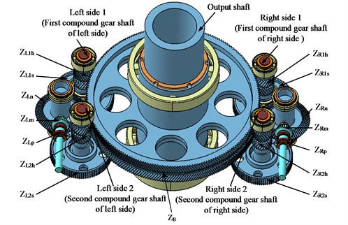
The schematic illustration of the split torque transmission in a helicopter main gearbox powered by two engines is shown in Fig. 1. It can be seen from the figure that the system has two power inputs, and is composed of three-stage drives. The structure and components of each transfer path are the same, and the components of two branch transmission subsystems are defined by subscripts and , respectively. In the first stage gear drive, the input bevel gear meshes with (, ). For the convenience of narration, the second stage is defined as the split torque stage. In this stage, the pinion meshes with two gears simultaneously, that is and . The final stage is the torque confluence stage, and gears of and all mesh with output gear at the same time.
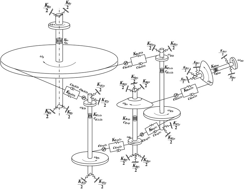
Fig. 2 shows a lumped-parameter dynamic model of this drive system, in which the moment of inertia of input and output components is included. Because the gear train arrangement is symmetrical, only a half of the edges is drawn in order to express the graph clearly. The gear mesh interface and the shaft are modeled as a spring-damper system, and the bearing is simulated with a spring. , and with appropriate subscript represent the stiffness, damping and transmission error respectively. The component of input shaft has five degrees of freedom: transverse motions in the -axis and -axis, axial motion in the -axis, and torsional angle of and input torsional angle . The component of shaft where mounts on also has five degrees of freedom: transverse motions in the -axis and -axis, axial motion in the -axis, and torsional angles of and . The component of shaft where (1, 2) mounts on has four degrees of freedom: transverse motions in the -axis and -axis, and torsional angle of and . The output shaft component also has four degrees of freedom: transverse motions in the -axis and -axis, and torsional angle of and output torsional angle . In this model, we have ignored the effects of motors, housing, coupling, and other practical phenomena such as backlash. Therefore, the whole model can be described by the total of 40 freedom degrees, and generalized displacement vector is given by:
where , , , , and represent the angular displacements of gears respectively. Displacements of the input shaft, split torque shaft, dual-gear shaft and output shaft are expressed by and , and , and , and , respectively. and are the axial displacements of the input shaft and the split torque shaft.
Fig. 1Schematic illustration of split torque transmission system
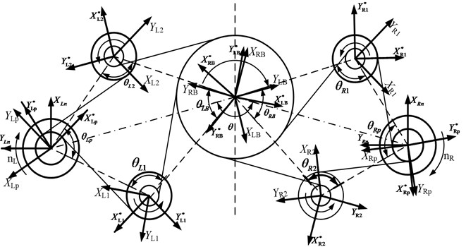
In order to facilitate the analysis of the dynamic system characteristics, the generalized coordinate system and local coordinate system are used, as shown in Fig. 3. In this figure, reference coordinate frames with superscript (*) are local, and the direction of and is coincident with the line of action for each particular meshing gears. , , , and are the angles between the center line of the gears. The pressure angle of gears is expressed by with the corresponding subscript. According to the geometric relations shown in the graph, the transformation relation between the generalized coordinates and local coordinates can be written as:
where and can be expressed as and . , , and can be expressed as , , and .
Fig. 2Dynamic model of transmission system
The displacements specified in these coordinate frames are described in only the global reference frame by transforming the local coordinate via rotational coordinate transformations, and will be used for a numerical calculation. For the unity of the symbols, let be used instead of , and – instead of .
Fig. 3Relationship of local and generalized system coordinates
3. Dynamic equations of split torque transmission system
3.1. Relationship between angular displacement and linear displacement
The relative displacement of the meshing gear pair in the direction of meshing line is defined as the dynamic transmission error. According to the geometrical relationships shown in Fig. 3, for split torque stages and torque confluence stages gears, the relationship displacement of the meshing line and the twist angle can be expressed as:
where , , and respectively express the relative displacement of and , and , and , and along the direction of the meshing line. , , , , and respectively express the base circle radius of , , , , and .
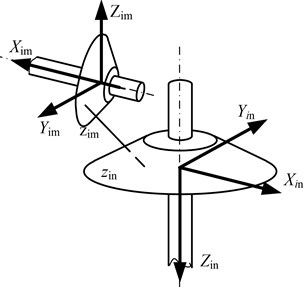
According to the coordinates of the input stage bevel gears shown in Fig. 4, the relation between the dynamic relative displacement along the meshing line and the rotation angle displacement of the bevel gears can be expressed as:
where and express the radius of mesh points of bevel gears. Calculation parameters , and can be expressed as:
where is the normal pressure angle of , is the helix angle, and is the pitch cone angle.
Fig. 4Input stage bevel gear coordinate system
The relative angular shaft displacement is transformed into the torsion line displacement, and it can be represented as:
where , , , and respectively express the torsion linear displacement of input shaft, split torque shaft, dual-gear shaft 1, dual-gear shaft 2 and output shaft. , , , and respectively express the equivalent radius of the shafts.
3.2. Mechanical analysis of gear transmission
Letting , and be meshing forces of input stage, split torque stages and torque confluence stages gear pairs respectively, then they can be represented as:
where , and are the derivative of the displacement, indicating the velocity. , and represent the time-varying meshing stiffness., and denote the gear mesh damping. The expressions of the time-varying meshing stiffness are the same [23], which can be expressed as:
where denotes the mean value of the time-varying meshing stiffness of the corresponding gear pairs, is the th order harmonic amplitude of the time-varying meshing stiffness, represents the angular frequency of the gear, and is initial phase angle. The expressions of gear mesh damping are the same [24], which can be expressed as:
where and represent the mass of the pinion and the gear, respectively, and is gear mesh damping ratio.
Letting and be the tooth surface frictions of split torque stages and torque confluence stages gear pairs, then they can be represented as:
where and respectively express the time-varying friction coefficient of the tooth surface. The calculation model of friction coefficient used in this paper is based on the theory of elasto-hydrodynamic lubrication theory (EHL), because the research shows that the friction coefficient based on the elasto-hydrodynamic lubrication theory is close to that obtained by experiment [25]. According to the calculation model, the friction coefficient can be expressed as:
where expresses the dynamic viscosity of lubricating oil, is the largest Hertzian contact stress, and is the root mean square of tooth flank roughness. , and express the entrainment velocity, slip-roll ratios and comprehensive curvature radius at the point of meshing tooth flank, respectively. The parameter to is the test parameter shown in Table 1.
Table 1Empirical parameters of EHL
Parameter | |||||||||
Value | –8.916 | 1.033 | 1.036 | –0.354 | 2.812 | –0.101 | 0.753 | –0.391 | 0.620 |
The meshing forces and friction can be decomposed into three components in the , and directions in the generalized coordinate system. Summing components in the same directions can obtain the resultant force on each shaft, which can be described respectively as follows:
3.3. Differential equations of transmission system
Utilizing the Lagrange equation, the vibration differential equations of the train system shown in Fig. 1 can be deduced. Under the action of input torques , and load , the torsional vibration differential equations of the gears can expressed as follows:
where is the friction torque of friction on the gear . Similarly, is the friction on the gear , and is the friction on the gear . The differential equations of transverse shaft vibration can expressed as follows:
According to the Eq. (3), Eq. (6) and Eq. (11), the torsional angle displacement of gears can be transformed into the linear displacement of gear pair along the line of action. So, this linear displacement vibration differential equation of split torque stages gear and can be expressed as:
where . Similarly, others linear displacement vibration differential equations can be obtained.
According to the Eq. (6) and Eq. (11), the torsional angle displacement of shafts can be transformed into the linear displacement. So, this linear displacement vibration differential equation can be expressed as:
Similarly, other differential equations of linear shaft displacement vibration can be obtained. Based on the above analysis, the differential equations of dynamics of the transmission system, which only contains the linear displacement, are obtained by simplifying.
4. Friction stiffness and friction torque coefficient
From Eq. (7) and Eq. (11), it can be seen that the friction and friction torque of gear pair are related to the factors such as the friction coefficient, meshing stiffness, friction arm and so on. The friction coefficient, mesh stiffness and friction arm are periodic functions with respect to time. In order to facilitate the subsequent calculation and analysis, the product of time-varying friction coefficient and time-varying meshing stiffness of gear pair is defined as the friction stiffness , and the product of time-varying friction stiffness and friction arm of gear pair is defined as the friction torque coefficient . They can be described as:
where is friction direction parameter. It is positive when the friction is in the positive direction of the coordinate system, and it will change at the pitch point. is the arm of friction.
4.1. Calculation of friction stiffness and friction torque coefficient of spur gear
Fig. 5(a) shows a schematic diagram of the spur gear meshing. The length of contact line remains unchanged and parallel to the axis when tooth contact begins and ends along the line of action. In a meshing period of gear teeth, the time-varying friction stiffness and friction torque coefficient, and , can be expressed as:
where is meshing stiffness of the unit contact line, the length of contact line. The total friction stiffness and friction torque coefficient of all engagement teeth are obtained by the superposition of the friction stiffness and the friction torque coefficient in a meshing period, which can be expressed as follows:
Fig. 5Engagement process of cylindrical gear
a) Spur gear
b) Helical gear
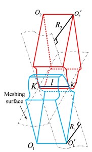
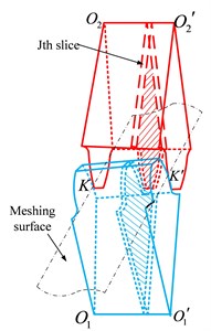
4.2. Calculation of friction stiffness and friction torque coefficient of helical gear
Fig. 5(b) shows a schematic diagram of the helical gear meshing. The initial contact of helical gear teeth starts as a point and changes into a line as the teeth come into closer engagement, and the contact line is diagonal across the tooth face. In order to calculate the total friction stiffness and friction torque coefficient of helical gear, the tooth can be cut into slices of unit length along the face width direction. Then each slice can be regarded as a spur gear. Based on the above analysis of spur gear, the time-varying friction stiffness and friction torque coefficient of the slice at a time can be obtained as follows:
where is unit contact line. Then the friction stiffness and friction torque coefficient of the meshing gear at a time can be describe as:
where is the number of the slices that are engaged at the moment. Substituting Eq. (17b) into Eq. (16b), the total friction stiffness and friction torque coefficient of gear teeth of all engaged helical gears are obtained by the superposition of the friction stiffness and friction torque coefficient in a meshing period.
5. Tooth surface friction and dynamic transmission error
To avoid the interference of gear meshing, the tooth matching formula is derived. Based on the power transmission of a helicopter, taking the minimum volume or the least weight as the target, the main transmission parameters shown in Table 2 are obtained by optimized designing. There are not good theoretical methods for solving the differential equations, because of the characteristics of multifactor coupling, time-varying and many degrees of freedom. Thus, the Fourier series method is used to solve the equations by transforming the time varying system into a linear time invariant system. Time-varying parameters are divided into a not-time-varying mean value part and time-varying volatility part with neglecting high-order quantities. After finishing, the equations are transformed into a linear constant system. With the gear frequency as the fundamental frequency, the excitation term of meshing stiffness fluctuation and the friction excitation are expanded into Fourier series by selecting the first few orders of frequency. Besides, error excitation is also expanded into Fourier series with the shaft frequency as the fundamental frequency. The total system response can be obtained after the superposition of the each order excitation response. When the Fourier method is used to solve the time history of vibration, the vibration spectrum is also obtained.
Table 2Main parameters of transmission system
Parameters | Values |
Input power / (kW) | 2000 |
Input speed / (r·min−1) | 20900 |
Normal module of input, split torque and torque confluence stage / (mm) | 3.85, 3.5, 44 |
Gear ratio of input, split torque and torque confluence stage | 27/74, 31/98, 23/215 |
Pressure angle of input, split torque and torque confluence stage / (°) | 20, 22.5, 20 |
Face width of input, split torque and torque confluence stage / (mm) | 45, 48, 100 |
Helical angle of input and torque confluence stage / (°) | 30 |
Installation angles of , and / (°) | 108, 104, 150 |
5.1. Analysis of friction stiffness and coefficient of friction torque of spur gear
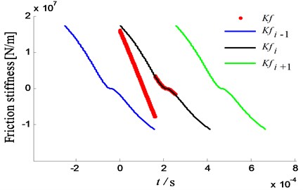
The calculation results of friction stiffness of spur gear are shown in Fig. 6. In the meshing process, the friction stiffness decreases gradually from the entry to pitch point. However, the value gradually increases in the reverse direction when the meshing point passes through the pitch point. That is because the value of relative sliding velocity and friction coefficient become larger and larger when the meshing point is far away from the pitch point, and the direction of relative sliding velocity between contact tooth flanks is changed. The results show that the friction stiffness in the entering meshing area is larger than that of the exiting meshing area.
Fig. 6Friction stiffness of spur gear
The change law of friction torque coefficient and friction stiffness is the same, as shown in Fig. 7. This result demonstrates that the friction torque of the driving gear is the same as the direction of driving torque, and the friction torque of the driven gear is the same as that of the load torque in the engaging process from the start point to the pitch point. However, the conclusion is opposite when the meshing point passes through the pitch point. In the whole meshing process, the absolute values of friction torque coefficient of the driving gear are maximal at the end point of engagement, and the largest values of that for the driven gear are located at the starting point of engagement.
Fig. 7Friction torque coefficient of spur gear
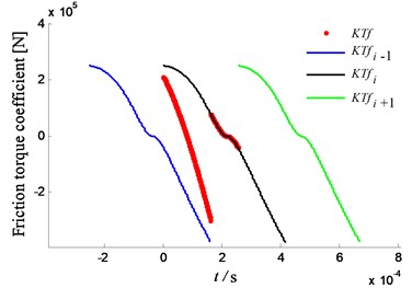
a) Friction torque coefficient of driving gear
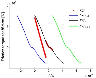
b) Friction torque coefficient of driven gear
5.2. Analysis of friction stiffness and coefficient of friction torque of herringbone gear
The calculation results of friction stiffness of herringbone gear (double helical gear) are shown in Fig. 8. Compared to a single helical gear, the friction stiffness curve changes gently, and the amplitude of the alternating component is small. Furthermore, compared with a spur gear, the stiffness curve is continuous without mutations, and the direction of friction stiffness is constant. Hence the resultant friction force direction is not changed for a herringbone gear train.
Fig. 8Friction stiffness of herringbone gear
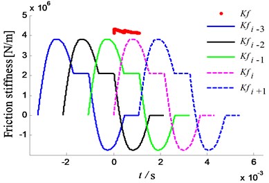
Fig. 9Friction torque coefficient of herringbone gear
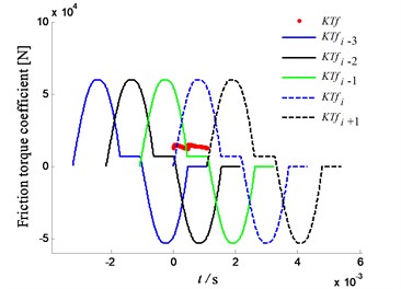
a) Friction torque coefficient of driving gear
b) Friction torque coefficient of driven gear
The change law of friction torque coefficient and friction stiffness is the same, as shown in Fig. 8. In addition, the amplitude of driving gear is smaller than that of the driven gear, as shown in Fig. 9. Compared with spur gear, the amplitude is small, and the direction of friction torque coefficient is unchanged.
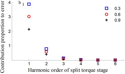
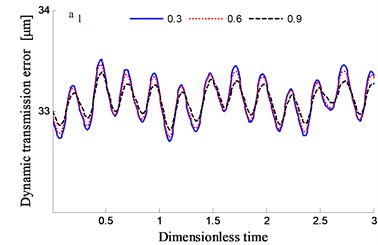
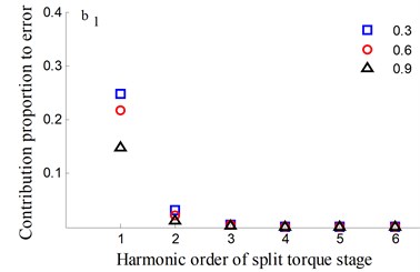
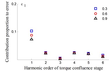
Fig. 10Transmission error along YRnp1s and contribution proportion of harmonic order
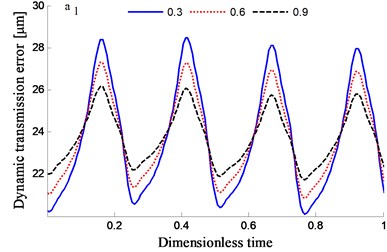
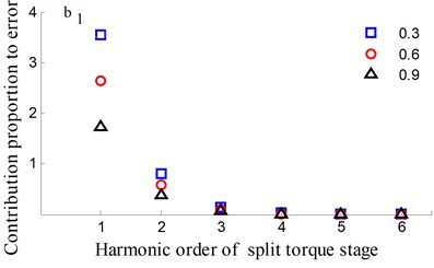
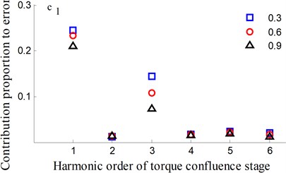
Fig. 11Transmission error along YRnp2s and contribution proportion of harmonic order
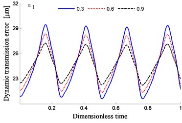
5.3. Analysis of dynamic transmission error
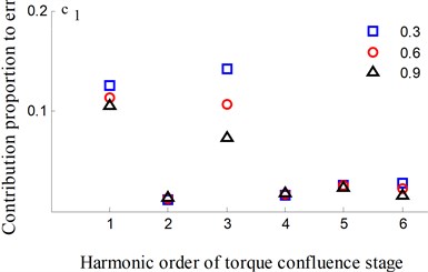
In order to study the influence of tooth flank roughness on the dynamic transmission errors of the system, a few of root mean squares of the roughness is analyzed to have 0.3, 0.6 and 0.9, respectively.
The time-frequency domain graphs of the dynamic transmission error along the line of action are shown in Figs. 10-17. After comparing the time domain diagram, we gain the results that the amplitude of the dynamic transmission error decreases with the increase of tooth surface roughness, and the trend is more obvious for the spur gear. Moreover, research results show that the friction and friction torque of the tooth flank increase with the increase of roughness. Due to the difference of friction torque coefficient, the gear meshing force decreases when the direction of friction and friction torque is opposite to the meshing force.
Fig. 12Transmission error along YRnB1h and contribution proportion of harmonic order
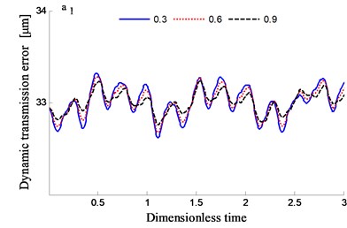
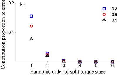
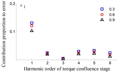
Fig. 13Transmission error along YRnB2h and contribution proportion of harmonic order
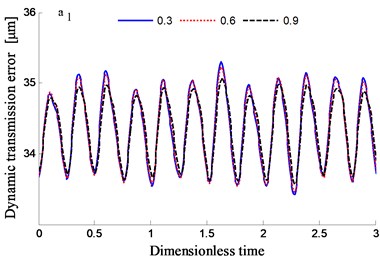
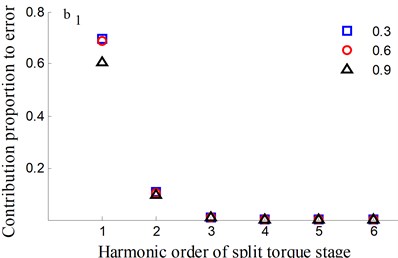
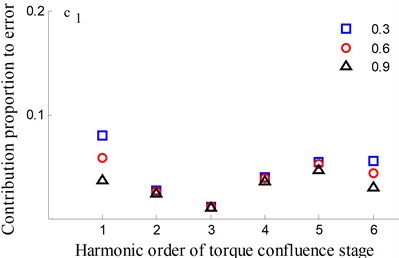
Fig. 14Transmission error along YLnp1s and contribution proportion of harmonic order
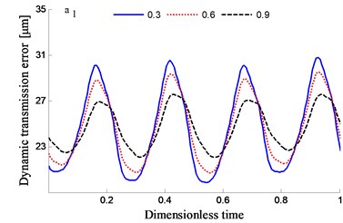
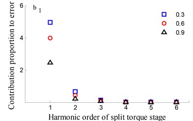
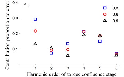
Fig. 15Transmission error along YLnp2s and contribution proportion of harmonic order
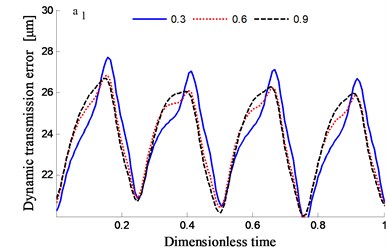
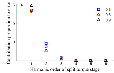
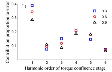
It could be observed from the frequency domain diagram that the influence of harmonic order of spur gear on the dynamic transmission error of each branch is mainly concentrated in the first and second orders. Besides, the harmonic order of herringbone gears also has some influence. With the increase of tooth surface roughness, the amplitude has a reduction in a different degree. Furthermore, the effects of harmonic order of split torque stages are significantly greater than those of torque confluence stages, as it can be seen from the error-contribution ratio. In addition, although the geometry of the drive system is symmetrical, and the torsional stiffness and support stiffness of the shaft are equal, the gear train force is asymmetric. Thus, the gear center will produce lateral micro-displacement, as a result the rotational deformations of the gears are different, and the power of two branches is out of balance. Due to large stiffness of torque confluence stages, the impact of tooth surface friction is mainly reflected in the split torque stages.
Fig. 16Transmission error along YLnB1h and contribution proportion of harmonic order
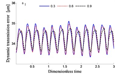
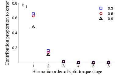
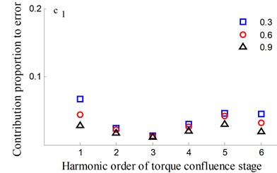
Fig. 17Transmission error along YLnB2h and contribution proportion of harmonic order
6. Conclusions
Based on the concentrated parameter theory, considering the influence of time-varying friction coefficient, time-varying meshing stiffness and the integrated error, a three-dimensional dynamic model with 41 degrees of freedom is developed, including the flexional, torsional and axial motions. According to the meshing characteristics of spur gears and helical gears, the calculation formulas of time-varying friction stiffness and friction torque coefficient are derived. The dynamic equations are solved by the Fourier series method, and the dynamic characteristics and the change law of system friction characteristics are obtained. Compared to a single helical gear, the friction stiffness curve of herringbone gear changes gently without mutations, and the direction is constant what makes the resultant friction force direction to be unchanged. The tooth surface roughness has a certain influence on the dynamic transmission error. Due to the asymmetry of the force caused by the structure and its deformation, as well as larger stiffness of torque confluence stages, the impact trend is more obvious for split torque stages. The first and second harmonic order frequencies of the split torque stage gears have an important influence on the dynamic transmission errors.
References
-
White G. New family of high-ratio reduction gear with multiple drive paths. Proceedings of the Institution of Mechanical Engineers, Vol. 188, Issue 1, 1974, p. 281-288.
-
White G. Design study of 375 kW helicopter transmission with split-torque epicyclic and bevel drive stages. Proceedings of the Institution of Mechanical Engineers, Part C: Journal of Mechanical Engineering Science, Vol. 197, Issue 4, 1983, p. 213-224.
-
White G. Split torque helicopter transmissions with widely separated engines. Proceedings of the Institution of Mechanical Engineers, Part G: Journal of Aerospace Engineering, Vol. 203, Issue 1, 1989, p. 53-65.
-
Krantz T. L. Dynamics of Split Torque Helicopter Transmission. NASA Technical Memorandum 106410, 1994, p. 1-43.
-
Krantz T. L. A Method to Analyze and Optimize the Load Sharing of Split Path Transmissions. NASA Technical Memorandum 107201, 1996, p. 1-21.
-
Cocking H. Advanced engineering gearbox design. Vertica, Westland Helicopters and Hovercraft PLC, Yeovil, England, Vol. 10, Issue 2, 1986, p. 213-215.
-
Smirnov G. Multiple-power-path non-planetary main gearbox of Mi-26 heavy-lift transport helicopter. Vertiflite, Mil Design Bureau, Moscow, Vol. 36, 1990, p. 20-23.
-
He S., Gmirya Y., Mowka F. Trade study on different design configuration of CH-53K main gearbox. American Helicopter Society 64th Annual Forum, Montreal, Canada, 2008.
-
Gmirya Yuriy, He Shulin, Buzel Gregory, LeighLeslie Load sharing test of the CH-53K split torque main gearbox. The American Helicopter Society 65th Annual Forum, 2009, p. 977-986.
-
Gmirya Yuriy, Alulis Matthew, Palcic Peter, LeighLeslie Design and development of modern transmission: Baseline configuration of CH-53K drive system. The American Helicopter Society 67th Annual Forum, 2011, p. 2323-2334.
-
Rashidi Majid, Krantz Timothy Dynamics of a Split Torque Helicopter Transmission. NASA Technical Memorandum 105681, 1992.
-
Krantz T. L., Rashidi Majid Vibration Analysis of a Split Path Gearbox. AIAA/SAE/ASME, San Diego, California, 1995.
-
Krantz T. L., Delgado I. R. Experimental Study of Split-Path Transmission Load Sharing. The American Society of Mechanical Engineers, San Diego, California, 1996.
-
Yang Zhen, Wang Sanmin, Fan Yesen Nonlinear dynamic characteristics of split-torque gear transmission system. Journal of Mechanical Engineering, Vol. 44, Issue 7, 2008, p. 52-57.
-
Du Jiajia, Wang Sanmin, Wang Ying Research on dynamic characteristics of the dual power path gear transmission. Machinery, Vol. 50, Issue 4, 2012, p. 10-12.
-
Zhang Ting, Li Yuxi, Wang Sanmin Research on static load sharing of the dual power path gear transmission. Journal of Mechanical Transmission, Vol. 36, Issue 3, 2012, p. 14-16.
-
Dong Hao, Fang Zongde, Wang Baobin, et al. Load-sharing characteristics of gear train with dual power split based on deflection compatibility. Journal of South China University of Technology, Vol. 40, Issue 5, 2012, p. 18-22.
-
Dong Hao, Fang Zongde, Wang Baobin, et al. Load sharing characteristics analysis of power split system based on deflection compatibility and clearance floating. Journal of Aerospace Power, Vol. 28, Issue 4, 2013, p. 872-877.
-
Zhao Ning, Wang Ruifeng, Jia Qingjian, et al. Study on load sharing method for parallel shaft split torque transmission system. Journal of Mechanical Transmission, Vol. 37, Issue 5, 2013, p. 13-16.
-
Gui Yongfang, Zhu Rupeng, Fu Bibo, et al. Impact of torsional stiffness on dynamic load sharing of cylindrical gear split-torque transmission system. Journal of Aerospace Power, Vol. 29, Issue 9, 2014, p. 2265-2268.
-
Gui Yongfang, Zhu Rupeng, Jin Guang Hu, et al. Dynamic and load sharing characteristic analysis of nonlinear cylindrical gear split-torque transmission system with backlash. Journal of Vibration and Shock, Vol. 33, Issue 18, 2014, p. 178-182.
-
Long Shanshan Research of Influence of Stiffness on Load Sharing Characteristics of Single-Input Split Torque Gear Transmission System. Master Thesis, Nanjing University of Aeronautics and Astronautics, China, 2017.
-
Calculation of Load Capacity of Spur and Helical Gears Part. ISO6336-1-6336-3, Geneva, 2006.
-
Liang Xihui, Zuo Ming J., Hoseini R. Mohammad Vibration signal modeling of planetary gear set for tooth crack detection. Engineering Failure Analysis, Vol. 48, 2015, p. 185-200.
-
Hai Xu Development of Generalized Mechanical Efficiency Prediction. The Ohio State University, 2005.
About this article

The authors are very grateful to editors and anonymous reviewers for their constructive comments. Those comments are all valuable and very helpful for revising and improving our paper, as well as have the important guiding significance to our researches. The author gratefully acknowledges the financial support of the National Natural Science Foundation of China (Grant No. 51475226).
