Abstract
Four-stage main helicopter transmission system occupies several strong points like good carrying capacity and is addressed by many scholars. However, the influence of variable parameters on natural characteristics in a three-engine helicopter, is not to be investigated, according to the limited published issues. Thus, in the study, a vibration model of the four-stage main helicopter transmission system is established through the lumped mass method. In the model, many factors, including time-varying meshing stiffness and torsional stiffness of gear shaft are considered. The differential equation of the system is solved via the Fourier method, 27-orders natural frequency and modal shape corresponded by each degree of freedom (DOF) of the system are obtained. The influence of the shaft torsional stiffness on the first five orders of the system natural frequency is studied. Besides, the impact of the matching relationship of key shafts’ torsional stiffness on the system stability is analyzed. These contributions would improve modification developments of four-stage deceleration helicopter in future.
1. Introduction
The four-stage main transmission system, which is capable of carrying heavy loads, is the main part of three-engine helicopters. The gear transmission system has three input branches, tail branch and planetary gear chain. It means it has a quite complicated structure and dynamic behavior [1]. Moreover, several dynamic factors like time-varying meshing stiffness, clearances and synthetic transmission errors influence the coupling gear pairs. In addition, the rotational speeds of shafts in each stage could have an impact on the system vibration. Therefore, it is meaningful to study its vibration characteristics.
For the research of vibration characteristics in a multi-shaft system, Kubur M. [2] proposed a dynamic model of multi-shaft helical gear reduction unit formed by flexible shafts and predicted free and forced vibrations of the system. Huang J. [3] investigated the influences of system parameters on the natural characteristics of a parallel multi-shaft gear-rotor system. Gu Z. [4] analyzed torsional vibration characteristics for the helicopter transmission system by the impedance matching method. Wang J. [5] studied torsional vibration of the helicopter transmission system by the whole transfer matrix. Wang M. [6] proposed a decision table for a fault diagnosis of the helicopter transmission system.
On the other hand, in terms of the planetary gear chain of main transmission system, Kahraman A. [7-12] analyzed natural modes of planetary gear trains, proposed a power flow analysis methodology and assemblability check methodology for planetary gear trains. Saada A. [13] discussed the influence of the ring support stiffness on free vibration and determined potentially dangerous frequencies for sun gear-planet and planet-ring gear contacts. Lin J. and Parker R. G. [14-16] investigated the natural frequency and vibration mode sensitivities to system parameters for both tuned (cyclically symmetric) and mistuned planetary gears. Velex P. [17] calculated dynamic tooth loads on a planetary gear set, and the original Ritz method was applied to solve large parametrically excited differential systems. Sheng D. P. [18, 19] proposed a nonlinear transverse-torsional coupled model with backlash and bearing clearance for planetary gear set and studied its load sharing behavior by the Rung-Kutta numerical integration method.
Although a lot of researches related to gear pairs, in this paper, a multi-shaft system and planetary gear train have been carried out and many models considering different parametric variables were proposed as well, it should be noted that, there is very few relevant researches based on the impact of shaft torsional stiffness on the vibration characteristics in a long transmission chain. The main purpose of this work is to explore the changes of shaft torsional stiffness on various orders of natural frequency, and to solve the natural frequency and modal shape corresponded by each DOF. Finally, the key shafts affecting the vibration characteristics of the helicopter were analyzed, and references could be provided for the helicopter design.
2. Dynamic modeling
A dynamic model of four-stage transmission system is shown in Fig. 1. As shown in the figure, the system has three same input branches, namely branch (1, 2, 3). Each branch has 5 gears. and are rotational DOF of drive bevel gear and passive bevel gear in the first stage deceleration; and are rotational DOF of drive bevel gear and passive bevel gear in the second stage deceleration; and are rotational DOF of drive gear and passive gear in the synthesized stage (third stage); is rotational DOF of the planet carrier; , and are rotational DOF of three gears in the tail transmission branch; and are rotational DOF of the sun gear and planet gear .
, , , , and are torsional stiffness of shafts connecting each gear pair; , , , and are meshing damping of each gear pair; , , , and are meshing stiffness of each gear pair. The flexibility between the shafts and transverse DOF are not taken into account due to its weak influence on the natural frequency.
Based on the description above, the four-stage deceleration helicopter transmission system, with 3 branches in the 1st and 2nd stage, has 27 generalized coordinates X (rotational DOF) as shown below, and Table 1 shows the corresponding relation between gears and their rotational DOF:
1) Time-varying meshing system stiffness.
The expansion formula of time-varying meshing stiffness is shown in Fourier series under the fundamental meshing frequency:
where is the fundamental meshing frequency of each pair; is the initial phase of meshing stiffness; , , , , , and are the time-varying meshing stiffness of the gear pair; and are the average and maximum variable meshing stiffness, here, consists of oil film stiffness and contact stiffness.
Fig. 1Model of three-engine helicopter transmission system
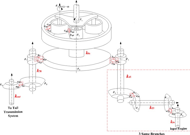
a) Dynamic model
b) FEM model

c) Boundary condition
2) Relative displacement of gear pair.
The relative displacement of each gear pair along the meshing line is defined as follows:
where , , , , , and are the relative displacement along the meshing line. , , , , , , , , , , and are radiuses of the base circle.
3) Dynamic meshing and damping forces.
Dynamic meshing and damping forces of each gear pair are defined as follows:
where , , , , , and are dynamic meshing and damping forces of each gear pair. , , , , , and are mesh damping forces of the engaged gear pair. , , , , , and are the relative velocity along the meshing line.
4) Differential equation of motion.
According to the analysis and equations above, the differential equation of the trial model system can be deduced through the Newton’s law, as shown below:
where is denoted as the output torque of engine (1, 2, 3); and are the output torque of the tail branch and planet carrier. and are dynamic meshing and damping forces of each gear pair.
In addition, after the decomposition and recombination of Eq. (4), it can be expressed with following matrix-vector form:
here [], [], [] are the mass matrix, damping matrix and stiffness matrix of the governing equation, and all matrices are in 27 dimensions; the matrix {} is external excitation.
Table 1Torsional DOF of each order
DOF | Name | DOF | Name | DOF | Name |
1 | Gear 1 (First Engine) | 10 | Gear 5 (Second Engine) | 19 | Gear 9 (Tail Transmission) |
2 | Gear 2 (First Engine) | 11 | Gear 1 (Third Engine) | 20 | Gear 10 (Sun Gear) |
3 | Gear 3 (First Engine) | 12 | Gear 2 (Third Engine) | 21 | Gear 11 (Planet Gear 1) |
4 | Gear 4 (First Engine) | 13 | Gear 3 (Third Engine) | 22 | Gear 12 (Planet Gear 2) |
5 | Gear 5 (First Engine) | 14 | Gear 4 (Third Engine) | 23 | Gear 13 (Planet Gear 3) |
6 | Gear 1 (Second Engine) | 15 | Gear 5 (Third Engine) | 24 | Gear 14 (Planet Gear 4) |
7 | Gear 2 (Second Engine) | 16 | Gear 6 (Synthesized Gear) | 25 | Gear 15 (Planet Gear 5) |
8 | Gear 3 (Second Engine) | 17 | Gear 7 (Tail Transmission) | 26 | Gear 16 (Planet Gear 6) |
9 | Gear 4 (Second Engine) | 18 | Gear 8 (Tail Transmission) | 27 | Planet Carrier |
3. Calculation and discussion
3.1. Model parameters and natural characteristics calculation
An example case of four-stage transmission system is listed in Table 2 and Table 3. Gear number is according to Table 1.
Table 2Gear parameters
Tooth number | Module | Face width (mm) | Initial phase of meshing stiffness (°) | |
Gear 1 | 30 | 4.5 | 40 | 0 |
Gear 2 | 85 | 4.5 | 40 | 0 |
Gear 3 | 40 | 5 | 60 | 20 |
Gear 4 | 90 | 5 | 60 | 20 |
Gear 5 | 25 | 4.75 | 40 | 30 |
Gear 6 | 142 | 4.75 | 40 | 30 |
Gear 7 | 40 | 5 | 35 | 0 |
Gear 8 | 60 | 5 | 35 | 0 |
Gear 9 | 70 | 5 | 40 | 20 |
Gear 10 | 68 | 5 | 40 | 20 |
Gear 11-16 | 37 | 5 | 40 | , , , , , |
By setting the value of damping item and external excitation item in Eq. (5) to be zero, the vibration differential equation of the system under free condition can be obtained, as shown in the following equation:
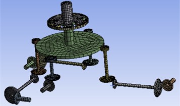
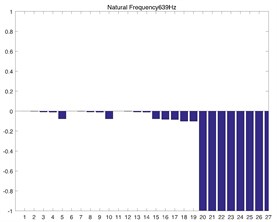
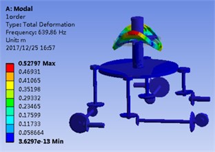
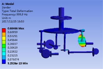
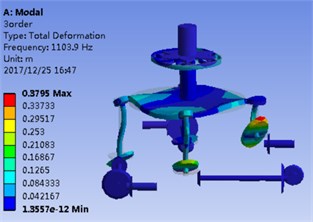
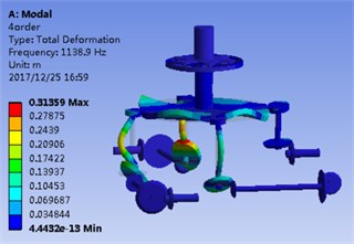
After solving Eq. (6), the natural frequency and modal shape of 27 orders corresponded by the system can be obtained. The modal shape corresponded by the natural frequency of various orders is shown in Fig. 2. Its -coordinate denotes 1-27 order DOF, and its y-coordinate denotes the modal shape corresponded by DOF. In addition, the FEM solution is calculated as well to verify the numerical model shape. The geometric model in CATIA is introduced into the ANSYS workbench 18.1, so a finite element analysis model is obtained. Gear pair is equivalent to a cylinder, which is same as the dynamic model. The hexahedral meshing method is applied for calculation, and then it refines the grid in contact areas, as shown in Fig. 1(b). The contact area is set as so separation, which is shown in Fig. 1(c). The grid size of the non-contact region of this model is defined as 3 mm, and the contact area is defined as 2 mm, which ensures the mesh rationality and the maximum efficiency, the results tend to converge when the number of nodes is 52874 and the number of elements is 15523.
Table 3System parameters
Parameter | Value (N/m) | Parameter | Value (N/m) | Parameter | Value (N·m/rad) |
12×108 | 6×10⁸ | 3×10⁵ | |||
8×10⁸ | 4×10⁸ | 6×10⁵ | |||
8×10⁸ | 4×10⁸ | 3×10⁵ | |||
7×10⁸ | 3.5×10⁸ | 6×10⁵ | |||
10×108 | 5×10⁸ | 9×10⁵ | |||
8×10⁸ | 4×10⁸ | 2×10⁵ | |||
8×10⁸ | 4×10⁸ | ||||
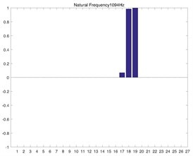
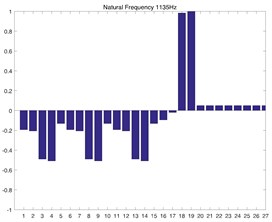
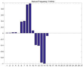
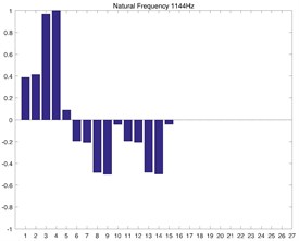
Fig. 2(a) and Fig. 2(b) correspond to the modal shape of the first-order natural frequency, showing that vibration occurs mainly in the planetary gear train, and there is no obvious vibration in the rest DOF. Fig. 2(c) and Fig. 2(d) correspond to the modal shape of the second-order natural frequency. According to Table 1, the tail transmission gears are 17, 18 and 19 DOF respectively. When there is vibration under the natural frequency of the second-order with only three gears of tail transmission operated, the other DOF did not vibrate. Fig. 2(e)-2(j) show the modal shape under the rest natural frequency, suggesting that multi DOF of the system results in vibration at different directions and with different sizes when the system operates under the natural frequency. According to the modal shape of each order in Fig. 2, it can be found out that apparent coupling action occurs in each stage of the transmission system, which needs a further analysis and exploration.
3.2. Analysis of natural frequency influenced by torsional stiffness of shafts
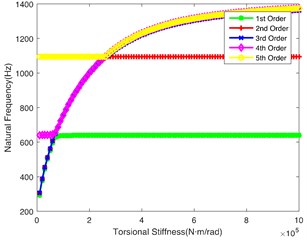
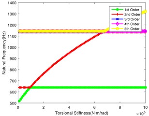
The helicopter has multiple deceleration stages, lots of branches and a great many shafts, which have the principal effects on the system. Torsional stiffness of these shafts is highlighted redly in Fig. 1(a), the changes of torsional stiffness can lead to different stiffness matrices, affecting the natural frequency accordingly. The influence of torsional stiffness on the natural characteristics are explored and shown in Fig. 3. Theoretical results are provided for a design of the helicopter shaft in order to avoid damage and failure.
Fig. 3(a) shows the impact of on the natural frequency. It indicates that this shaft hits the lower frequency respectively, which easily tends to cause resonance. In the other words, this shaft is the key shaft. In addition, when is no less than 8×10⁴N·m/rad, the 1st order natural frequency remains 640 Hz, while the natural frequency of the rest orders continues to increase; when is greater than 2.2×10⁵ N·m/rad, 2nd order natural frequency remains 1100 Hz, while natural frequency of the rest orders gradually tends to be stable; the 3rd order, 4th order and 5th order natural frequencies always increase with the rise of .
Fig. 2Model shape of transmission system corresponded by first 5 orders
a) 1st order numerical solution
b) 1st order FEM solution
c) 2nd order numerical solution
d) 2nd order FEM solution
e) 3rd order numerical solution
f) 3rd order FEM solution
g) 4th order numerical solution
h) 4th order FEM solution
i) 5th order numerical solution
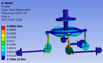
j) 5th order FEM solution
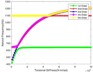
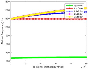
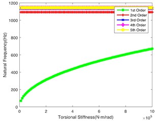
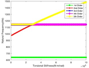
Fig. 3(b) demonstrates the impact of on the natural frequency, showing similar laws to Fig. 3(a). However, the 2nd order natural frequency remains stable at 1100 Hz when is greater than 4.5×10⁵ N·m/rad. At the same time, the abrupt change point of the 5th order is 4.5×10⁵ N·m/rad. Fig. 3(c) shows the impact of on the natural frequency. It can be seen that the change of torsional stiffness slightly impacts the natural frequency of the first 5 orders. Fig. 3(d) shows the impact of on the natural frequency. It can be seen that 1st order natural frequency increases almost linearly, while the natural frequency of other orders shows a little change along with the increase of ; it crosses the low frequency regions when is lower, so the shaft is also a key shaft, and its torsional stiffness () cannot be too low. Fig. 3(e) and Fig. 3(f) respectively show the influence of and on the natural frequency. The values of natural frequency of all orders show similar trends. is relatively important in the tail transmission branch because it hits the lower frequency in the 1st and 2nd orders.
Fig. 3Impact of each shaft’s torsional stiffness on first five orders natural frequency
a)
b)
c)
d)
e)
f)
Through the comprehensive comparison of the above figures, it can be found that and have greater influence on the 1st natural frequency; and have greater influence on the 2nd natural frequency.
3.3. Analysis of matching relationship of key shaft’s torsional stiffness
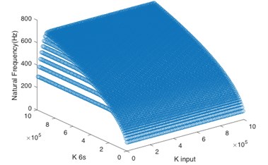
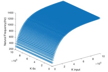
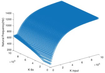
In the paper, the system stability was enhanced through changing the torsional stiffness of key shafts to avoid the resonance frequency. According to the aforementioned analysis, the system input shaft () and sun gear input shaft () are the key shafts. By changing the values of torsional stiffness of these two shafts respectively, the matching relationship between their stiffness value and natural frequency of the first five orders was calculated.
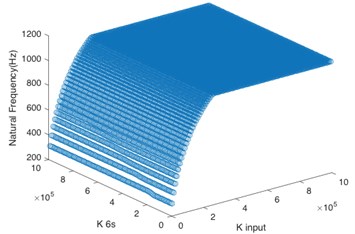
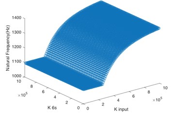
According to Fig. 4(a), for the first order natural frequency, the torsional stiffness of two shafts must not be too low at the same time so as to avoid the resonance frequency, and the torsional stiffness of sun gear input shaft is dominant. Based on Fig. 4(b) and Fig. 4(c), the system input shaft mainly controls the natural frequency of the second order and third order. When is greater than 2×10⁵ N·m/rad, even if the sun gear input shaft has low stiffness, the system can maintain stability. It can be seen from Fig. 4(d) that the torsional stiffness of two shafts must not be too low at the same time for the natural frequency of the fourth order. Besides, Fig. 4(e) shows that the natural frequency of the fifth order is greater than 1100 Hz no matter how to change the torsional stiffness of two shafts, so the torsional stiffness of these two shafts doesn’t have effect on the system stability in the natural frequency of the fifth order if the operating frequency is lower than 1100 Hz.
Fig. 4Matching relationship on torsional stiffness of key shafts
a) 1st order
b) 2nd order
c) 3rd order
d) 4th order
e) 5th order
4. Conclusions
In this paper, a model of the four-stage helicopter transmission system is proposed, and the differential governing equation of system vibration is derived as well. Based on the governing equation, the natural characteristics and modal shape are obtained by employing the Fourier series method. Furthermore, this paper presents the influence of the changes of torsional stiffness on various orders of natural frequency. In addition, the matching relationship of key shafts in the system is calculated to estimate their combined effect on each order.
The analysis results enable us to draw the following conclusions:
1) When the four-stage deceleration helicopter transmission system operates under the natural frequency, each DOF of the system produces vibrations at different directions and with different sizes, and the transmission at all stages shows an obvious coupling effect.
2) The modal shape under the first-order natural frequency occurs mainly in the planetary gear train; the second-order and third-order natural frequency mainly affects the tail transmission branch.
3) The system input shaft () and sun gear input shaft () are the key shafts of the system, and the system is in the low frequency region when their torsional stiffness is low and tends to have resonance.
4) The system input shaft () as well as Gear 2 and Gear 3 connecting shafts () greatly impact on the second-order and third-order natural frequency; Gear 7 and Gear 8 connecting shaft () is the most important shaft in the tail transmission branch.
5) For the first order natural frequency, torsional stiffness of two key shafts must not be too low at the same time so as to avoid resonance frequency; and the torsional stiffness of sun gear input shaft () is dominant; for natural frequency of the fifth order, neither torsional stiffness of two key shafts affects the system stability if the operating frequency is lower than 1100 Hz.
References
-
Bianchi A., Rossi S. Modeling and finite element analysis of a complex helicopter transmission including housing, shafts and gears. European Rotorcraft Forum, 1997.
-
Kubur M., Kahraman A., Zini D. M., et al. Dynamic analysis of a multi-shaft helical gear transmission by finite elements: model and experiment. Journal of Vibration and Acoustics, Vol. 126, Issue 3, 2004, p. 398-406.
-
Huang J., Zhang S., Zhang Y. The influences of system parameters on the natural characteristics of a parallel multi-shaft gear-rotor system. Machinery Design and Manufacture, Vol. 7, 2013, p. 15-17, (in Chinese).
-
Gu Z., Yang J. Analyses of torsional vibration characteristics for transmission system of helicopter. Journal of Nanjing University of Aeronautics and Astronautics, Vol. 29, Issue 6, 1997, p. 674-678, (in Chinese).
-
Wang J., Mao Z., Qin L. Analysis of whole transfer matrix on torsional vibration of helicopter’s transmission system. Journal of Aerospace Power, Vol. 23, Issue 10, 2008, p. 1805-1812, (in Chinese).
-
Wang M., Hu N., Qin G. A method for rule extraction based on granular computing: application in the fault diagnosis of a helicopter transmission system. Journal of Intelligent and Robotic Systems, Vol. 71, Issues 3-4, 2013, p. 445-455.
-
Kahraman A. Natural modes of planetary gear trains. Journal of Sound and Vibration, Vol. 173, Issue 1, 1994, p. 125-130.
-
Kahraman A. Free torsional vibration characteristics of compound planetary gear sets. Mechanism and Machine Theory, Vol. 36, Issue 8, 2001, p. 953-971.
-
Kahraman A., Ligata H., Kienzle K., et al. A kinematics and power flow analysis methodology for automatic transmission planetary gear trains. Journal of Mechanical Design, Vol. 126, Issue 6, 2004, p. 1071-1081.
-
Inalpolat M., Kahraman A. A dynamic model to predict modulation sidebands of a planetary gear set having manufacturing errors. Journal of Sound and Vibration, Vol. 329, Issue 4, 2010, p. 371-393.
-
Kwon H. S., Kahraman A. An assemblability check methodology for the kinematic configurations of automatic transmission planetary gear trains. Journal of Mechanical Science and Technology, Vol. 30, Issue 12, 2016, p. 5605-5616.
-
Ahraman A., Hilty D. R., Singh A. An experimental investigation of spin power losses of a planetary gear set. Mechanism and Machine Theory, Vol. 86, 2015, p. 48-61.
-
Saada A., Velex P. An extended model for the analysis of the dynamic behavior of planetary trains. Journal of Mechanical Design, Vol. 117, Issue 2, 1995, p. 241-247.
-
Lin J., Parker R. G. Analytical characterization of the unique properties of planetary gear free vibration. Journal of Vibration and Acoustics, Vol. 121, Issue 3, 1999, p. 316-321.
-
Lin J., Parker R. G. Sensitivity of planetary gear natural frequencies and vibration modes to model parameters. Journal of Sound and Vibration, Vol. 228, Issue 1, 1999, p. 109-128.
-
Lin J., Parker R. G. Planetary gear parametric instability caused by mesh stiffness variation. Journal of Sound and Vibration, Vol. 249, Issue 1, 2002, p. 129-145.
-
Velex P., Flamand L. Dynamic response of planetary trains to mesh parametric excitations. Journal of Mechanical Design, Vol. 118, Issue 1, 1996, p. 7-14.
-
Sheng D. P., Zhu R. P., Jin G. H., Lu F. X., Bao H. Y. Dynamic load sharing behavior of transverse-torsional coupled planetary gear train with multiple clearance. Journal of Central South University, Vol. 7, Issue 22, 2015, p. 2521-2532.
-
Sheng D. P., Zhu R. P., Jin G. H., Lu F. X., Bao H. Y. Dynamic load sharing characteristics and sun gear radial orbits of double-row planetary gear train. Journal of Central South University, Vol. 10, Issue 22, 2015, p. 3806-3816.
About this article

This work is supported by the National Natural Science Foundation of PRC (Grant No. 51775265 and 51475226); China Scholarship Council (Grant No. 201606830019); and Postgraduate Research and Practice Innovation Program of Jiangsu Province.
The authors thanks for the project ‘Dynamic Analysis on Four-stage Main Transmission System’ (Grant No. KYCX17_0242) for supplying the gear data.
