Abstract
The pivot-jewel bearing pair is the only dynamic and static contact component of the flexible vertical rotor system, and its support stiffness directly affects the dynamic response of the rotor system. A non-linear dynamic model of the vertical rotor system is established, and the effect of different elastic pivot stiffnesses on the dynamic behavior of the rotor system is investigated in combination with experiments. The results show that with the increase of rotational speed, the system has the dynamic characteristics of alternating period 1 and quasi period, and when the speed reaches 550 r/s, 1/3 times low frequency whirl occurs and when the speed rises to 675 r/s, the low frequency amplitude is higher than the rotational frequency amplitude. With the increase of the elastic pivot stiffness, the amplitude of the low frequency whirl at the lower end of the rotor decreases continuously but the proportion of the “width” gradually increases. The rotational speed corresponding to the large amplitude quasi periodic motion of the rotor is delayed from 550 r/s to 650 r/s. The research results can provide a theoretical basis for the optimal design of the bearing subsystem of the vertical rotor system.
Highlights
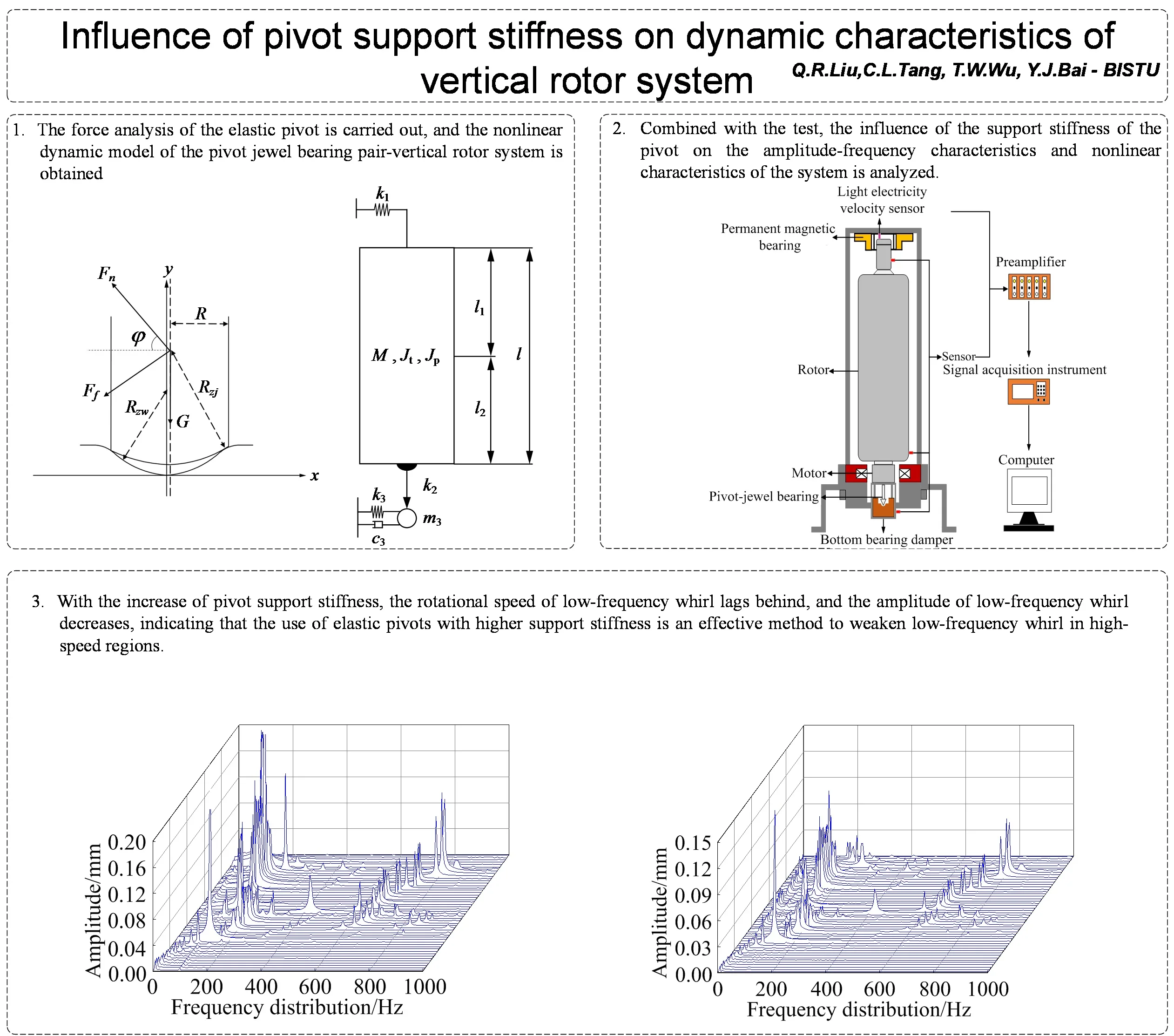
- The force analysis of the elastic pivot is carried out, and the nonlinear dynamic model of the pivot jewel bearing pair-vertical rotor system is obtained.
- Combined with the test, the influence of the support stiffness of the pivot on the amplitude-frequency characteristics and nonlinear characteristics of the system is analyzed.
- With the increase of pivot support stiffness, the rotational speed of low-frequency whirl lags behind, and the amplitude of low-frequency whirl decreases, indicating that the use of elastic pivots with higher support stiffness is an effective method to weaken low-frequency whirl in high-speed regions.
1. Introduction
Pivot-jewel bearing is composed of elastic pivot with spherical end and a bowl-shaped artificial gemstone; compared with other sliding supports, it has the advantages of anti-wear, slow friction torque, and high compressive strength. It is suitable for use as the lower support of energy storage fly wheel and centrifuge. This rotor system is usually of vertical structure. The upper support is a magnetic bearing, and the lower end uses elastic pivot and a jewel bearing to form a friction pair. Rotor vibration is transmitted to the damper at the lower end of the rotor through the single point contact interface between the pivot and the jewel bearing. Unlike the typical precision instruments with jewel bearing, the contact area size of the bearing pair is in the millimeter range and the system speed can reach tens of thousands of revolutions per minute. The support stiffness characteristics of the flexible pivot have a significant impact on the stable operation of the rotor system.
The dynamic behavior of vertical rotor systems has been studied in depth by domestic and international scholars. Nishimura [1] studied the non-linear vibration characteristics of a vertical rotor-sliding bearing system and analyzed the effects of fluid viscosity, radial clearance, bearing support stiffness, and damping coefficient on the dynamic behavior of the system. M. F. White [2] studied the influence of system parameters and non-linear bearing forces on the dynamic response characteristics of vertical rotor systems. It was concluded that the bearing radius clearance is an important parameter affecting the dynamic characteristics and stability of the rotor system. V. F. Ovchinnikov [3] investigated the influence of the structural deviation caused by the non-orthogonality of the axial magnetic bearing disk on the dynamic characteristics of the rotor system in normal operation mode and during seismic disturbances for the vertical rotor-magnetic bearing system. Luneno J. C. [4] established a dynamic model of a vertical rotor-bearing system and analyzed the effect of bearing parameters on the system amplitude and frequency response in combination with experiments. Guangming Yang [5] measured the connection stiffness between the flexible pivot and the jewel bearing and analyzed its effect on the stability of the vertical rotor. Zhengguang Li [6-7] improved the original vertical rotor model and examined the effect of parameters such as friction coefficient and speed on the dynamic response characteristics of the system in combination with experiments. Xia Wang [8] established a non-rigid connection model for the pivot-jewel bearing and studied the effect of bearing friction on the vibration characteristics of a vertical rotor system by varying the bearing load capacity to change the friction force. Tingwei Wu [9] established a non-linear connection model for the pivot-jewel bearing and simulated the effect of the degree of wear of the bearing pair on the dynamic response characteristics of a vertical rotor system by varying the radial friction coefficient. Minyu Wang [10] used IMPACT function-based finite element software to model the bearing contact of a vertical rotor system and investigated the effect of bearing load bearing on the dynamic response characteristics of the rotor when the pivot-jewel bearing was in point contact and line contact. Xingjian Dai [11-13] investigated the dynamic behavior of a vertical rotor and a limiter with a large asynchronous feed and discussed the role of unevenness and friction parameters in the system dynamics.
This paper focuses on the influence of the elastic pivot support stiffness on the dynamic behavior of the vertical rotor system. The Lagrangian energy method is used to establish a non-linear dynamic model of the flexible vertical rotor system, and the effect of the elastic pivot support stiffness on the amplitude-frequency characteristics and non-linear characteristics of the system is calculated and analyzed.
2. Non-linear dynamics model for vertical rotor systems
2.1. Rotor system simplification and mechanical modeling
The structure diagram of the rotor system is shown in Fig. 1. The rotor is a vertical thin-walled structure, and the whole is in a high vacuum environment. The upper end of the rotor is supported by a permanent magnet bearing as a non-contact support to provide radial stiffness; The lower end of the rotor is supported on a jewel bearing by a low support stiffness elastic pivot, and the jewel bearing is fixed on the oil damper damping body. The oil damper damping body is fixed on the damper housing by a spring, which plays an alignment role and provides radial stiffness for the damping body. The oil film in the damper housing provides damping for the vibrating body and lubrication for the pivot-jewel bearing. The rotor is fixedly connected to the rotor of the disc motor, which has the characteristics of a simple structure and high efficiency.
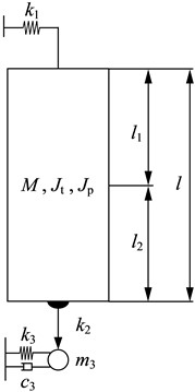
In order to study the dynamic characteristics of the vertical rotor system, the following simplifying assumptions are adopted: (1) the rotor is subcritical and approximated as a rigid body; (2) the upper support unloads the rotor axially and provides radial stiffness; (3) the lower damping member described performs only translational motion and cannot rotate; (4) the rotor performs transverse micro-amplitude vibration; (5) the pivot is equivalent to a massless spring. The simplified system dynamics model is shown in Fig. 2.
In Fig. 2, is the magnetic bearing transverse stiffness, is the equatorial rotational inertia, is the polar rotational inertia, is the rotor mass, is the rotor length, is the distance between the center of gravity and the upper end of the rotor, is the distance between the center of gravity and the lower end of the rotor, is the equivalent transverse stiffness of the elastic pivot, is the equivalent mass of the lower damper, is the equivalent transverse stiffness of the lower damper, is the lower damper is the damping factor.
Fig. 1Schematic diagram of the structure of the flexible vertical rotor system
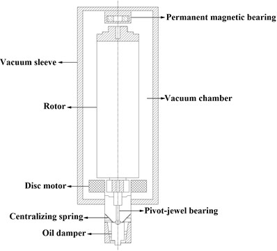
Fig. 2The dynamic model of a flexible vertical rotor system
2.2. Force analysis of elastic pivots
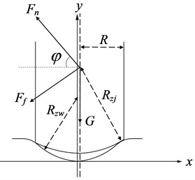
The geometry of the pivot-jewel bearing pair is shown in Fig. 3, where the solid line is the outer profile of the pivot and jewel bearing, where is the radius of the pivot, is the radius of the spherical surface of the pivot, is the radius of curvature of the jewel bearing, is the gravitational force of the rotor, is the normal support force and is the frictional force.
Fig. 3Schematic diagram of bearing sub-force
When the pivot is in contact with the jewel bearing, and the support force of the jewel-bearing socket on the pivot is:
where, is the viscous damping factor typical to the contact collision, is the relative displacement between the pivot and the jewel ball socket, is the relative velocity between the pivot and the jewel ball socket, is generally taken as 3/2 according to Hertz contact theory, and is the energy consumption factor.
The frictional force between the pivot and the jewel bearing is:
where, is the coefficient of sliding friction. In practice, the bearing friction coefficient is between 0.05 and 0.09 [14]
The force on the pivot is decomposed into the and directions and then synthesized to obtain the resultant force on the pivot in the and directions:
In Eq. (3):
2.3. Non-linear dynamics equations for rotor systems
The energy method is used to derive the kinetic energy, potential energy, and dissipation energy of the system. Substituting them into the Lagrange equations, the nonlinear dynamics equation of the rotor system can be obtained, as shown in Eq. (4):
where:
where and is the displacement of the upper end of the rotor, and is the displacement of the lower end of the rotor, and is the displacement of the lower damping body, represents the amount of unevenness at the upper and lower tips of the rotor, and represent the combined force on the elastic pivot in the and direction. The methods for solving differential equations include Runge-Kutta method, Newmark method and finite integral method. The Runge-Kutta method is a high-precision single-step algorithm widely used in engineering. It is characterized by high algorithm precision and measures to suppress errors. The disadvantage is that the realization principle is relatively complicated. The Newmark method is a commonly used numerical method for solving nonlinear dynamic problems. It has the characteristics of high precision, good stability, easy implementation and wide application range. The finite integration method has the characteristics of high precision, high stability, large time step and high calculation efficiency, which can greatly reduce the calculation time. Finally, the dynamic equation is solved by using the finite integral method.
3. Influence of elastic shaft tip support characteristics on the dynamic behavior of the system
The parameters of the rotor system are shown in Table.1, and the time domain characteristics of the system are obtained by substituting them into Eq. (4), which takes the Fast Fourier Transform to obtain the frequency-domain characteristics of the system.
Table 1Parameters of flexible vertical rotor system
Parameters | Value | Parameters | Value |
1800 N/m | 0.025 kgm2 | ||
0.0081 kg m2 | 1.35 kg | ||
0.6 m | 0.3 m | ||
0.3 m | 13.5 N | ||
10000 N/m | 0.05 kg | ||
1200 N/m | 15 Ns/m | ||
2.55 mm | 1.5 mm | ||
2.5 mm | 1 | ||
3/2 | 3.4 g⋅cm ∠0° | ||
1.8 g⋅cm ∠0° |
3.1. Effect of support stiffness on the system amplitude-frequency response
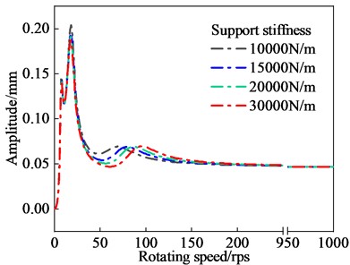
As shown in Fig. 4, the amplitude-frequency curve of the lower end of the rotor with different pivot support stiffness. From the diagram, it can be seen that during the acceleration process, the shaft system will pass three critical speeds, which are 8 r/s, 20 r/s and 80 r/s. After exceeding the critical speed, the amplitude decreases rapidly as the speed increases, which is the automatic centering effect of the high-speed rotor, and the amplitude of the lower end of the rotor is stabilized at 0.05 mm. When the shaft tip stiffness increases from 10000 N/m to 30000 N/m, the first two critical speeds and their resonance peaks change little. The third-order critical speed increases from 80 r/s to 100 r/s, but the resonance peak does not change much.
Fig. 4Amplitude frequency curve of the lower end of the rotor with different bearing support stiffness
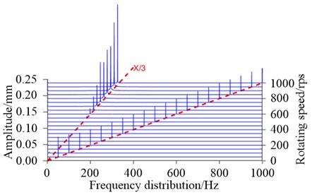
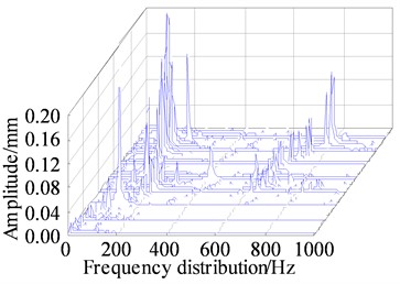
The three-dimensional waterfall diagram of the lower end of the rotor is shown in Fig. 5, through which the vibration characteristics of the system in the time-frequency domain can be visualized. When the speed is between 0 and 550 r/s, the rotor carries out the same frequency vibration; when the speed exceeds 550 r/s, the system exists 1/3 of the low frequency. According to previous studies, the cause of 1/3 low-frequency and other harmonic vibrations may be related to the characteristics of friction and looseness of bearings [21, 22]. As the speed increases, the low frequency amplitude gradually increases, and when the speed reaches 675 r/s, the low frequency amplitude even exceeds the same frequency amplitude and dominates. The increasing amplitude of the low frequency eddy current may lead to the dynamic instability of the rotor.
Fig. 5Waterfall diagram of the lower end of the rotor
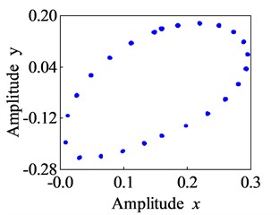
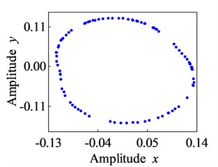
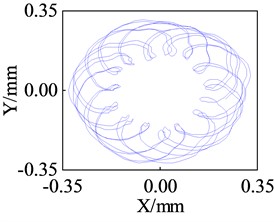
The change of low-frequency whirl is observed using the axis trajectory of the lower end of the rotor. Fig. 6 shows the axis orbit diagram corresponding to different shaft tip stiffness at 1000 r/s. It can be seen that as the support stiffness increases, the radius of the axis trajectory gradually decreases; that is, the vibration amplitude of the low-frequency whirl decreases from 0.35 mm to 0.18 mm, a reduction of 51 %, but the “width” of the low-frequency whirl gradually increases. From the perspective of reducing the amplitude of low-frequency whirl, increasing the stiffness of the elastic shaft tip has a positive effect.
Fig. 6Simulation of axis center track at the lower end of rotor (ω= 1000 r/s)
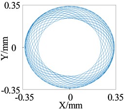
a)= 10000 N/m
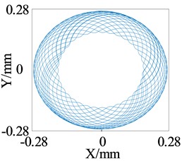
b)= 15000 N/m
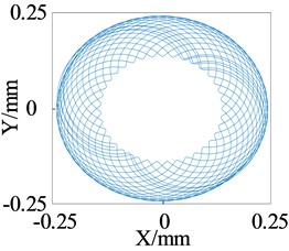
c)= 20000 N/m
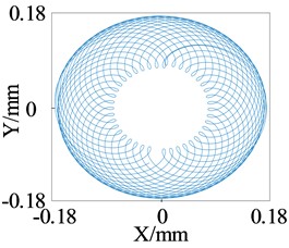
d)= 30000 N/m
3.2. Effect of support stiffness on the nonlinear characteristics of the system
The effect of pivot end support stiffness on the nonlinear characteristics of the system can be analyzed by means of the bifurcation diagram and the Poincare cross-section. It can be seen from Fig. 7 that the stiffness of the pivot support ranges from 10000 N/m to 20000 N/m. When the speed is less than 550 r/s, the system performs a stable motion with a period of 1. As the speed increases, the amplitude gradually increases. When the speed exceeds 550 r/s, the amplitude increases considerably. The Poincare section shows a closed ring, indicating that the rotor is performing a quasi-periodic motion.
Fig. 7Bifurcation diagram and Poincare section of the lower rotor (k2 = 10000 N/m)
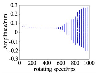
a) Bifurcation diagram
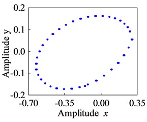
b) Poincare section (1000 r/s)
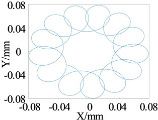
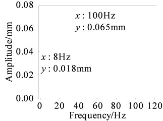
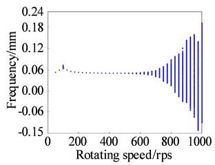
By increasing the pivot support stiffness, the dynamic response of the rotor system will change significantly. As shown in Fig. 8, when the support stiffness is in the range of 20000 N/m to 30000 N/m, and the rotational speed reaches 100 r/s, it can be seen from the spectrum that the rotor has more low frequencies in addition to the rotational frequency, where the low frequency of 8 Hz corresponds to the axial trajectory in the shape of a circular spiral, and the Poincare section shows a closed circle, with obvious characteristics of the proposed cycle.
Fig. 8Shaft trajectory and spectrogram of the lower end of rotor (ω= 100 r/s)
As shown in Fig. 9, the rotor motion at these points exhibits a variation pattern: period 1 → quasi-period → period 1 → quasi-period. period. Specifically, when the rotational speed is less than 100 r/s, the rotor moves in period 1. When the rotational speed reaches 100 r/s, it exhibits a quasi-periodic response with a small amplitude. As the rotational speed increases, once it surpasses 650 r/s, the rotor enters a quasi-periodic motion with a larger amplitude. Comparing this with the pivot stiffness of 10,000 N/m, when the pivot stiffness is increased, the corresponding rotational speed for the rotor to display a large amplitude quasi periodic motion is delayed from 550 r/s to 650 r/s. This indicates that a higher pivot stiffness expands the stable operating speed range of the rotor.
4. Experimental research
A flexible vertical rotor system test rig was built to test the vibration characteristics of the rotor system at different flexible pivot supports.
Fig. 9Bifurcation diagram and Poincare section of the lower rotor (k2= 30000 N/m)
a) Bifurcation diagram
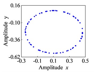
b) Poincare section (100 r/s)
c) Poincare section (650 r/s)
d) Poincare section (800 r/s)
4.1. Testing apparatus
A flexible vertical rotor system test stand is shown in Fig. 10, in which the rotor is a single-section thin-walled form with a permanent magnet bearing at the upper end to provide axial unloading force, and the lower end is supported on the jewel ball socket through the elastic pivot. The jewel ball socket is fixed with the lower damper damping body, providing damping and oil bath lubrication for the jewel bearing. The disc hysteresis motor and frequency converter fixed at the bottom of the rotor can realize the speed adjustment from 0 to 60,000 rpm.
Fig. 10Diagram of rotor test bench
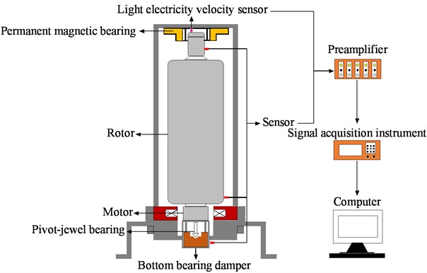
Eddy current position sensors are arranged at the upper and lower ends of the rotor and the and directions of the lower dampers, respectively, to measure the vibration amplitude; photoelectric sheets are affixed at the upper end of the rotor, and photoelectric speed sensors are installed to measure the system speed; the vibration displacement signals are transmitted to the NI acquisition card of the IPC through the preamplifier, the IPC model is PXIE-1062Q and PXI-4461 is used to acquire the vibration signals, which are transmitted by PXIE-8360 and PCIE-8361 to the vertical rotor system vibration monitoring platform developed on the basis of LabVIEW. The platform can monitor and analyze the time domain signal, amplitude and frequency response, frequency spectrum, axis trajectory and other time and frequency domain characteristics of the system in real-time.
4.2. Analysis of experimental results
In the test, one end of the elastic pivot is installed with the bottom interference fit of the rotor shaft hole, the other end is supported on the gem ball nest. Its two ends are under the boundary conditions between the cantilever beam and the free beam, and the elastic pivot support stiffness is shown in Eq. (5) through the cantilever beam deflection and bending stiffness formula:
where is the modulus of elasticity of the pivot material T10 steel, taken as 210 GPa, is the moment of inertia of the section, and is the length of the pivot, taken as 25 mm.
Fig. 11Comparison of the theoretical and experimental waterfall diagram of the lower rotor
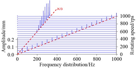
a) Simulation (= 15000 N/m)
b) Experiment (Shaft diameter is 1.65 mm)
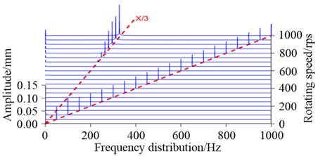
c) Simulation (= 30000 N/m)
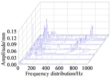
d) Experiment (Shaft diameter is 2 mm)
To verify the influence of different pivot support stiffnesses on the dynamic characteristics, four types of elastic pivots with varying journal diameters were processed for experiments: 1.5 mm, 1.65 mm, 1.8 mm, and 2 mm, respectively. The resulting supporting stiffness values were approximately 10002 N/m, 14670 N/m, 20777 N/m, and 31667 N/m. The pivots with different diameters were replaced to conduct rotor speed-up operation tests, and the dynamic response characteristics of the rotor system were analyzed within the support stiffness range of 10000 N/m to 30000 N/m.
Three-dimensional waterfall plots for pivot diameters of 1.65 mm and 2 mm, respectively, are shown in Fig. 11. The waterfall plots allow observing the spectral distribution and vibration amplitude of the rotor lifting speed process. As can be seen from the graphs, when the pivot support stiffness is 15000 N/m, both the simulation and the test produce low-frequency eddy motion at around 600 Hz. As the speed increases, the low-frequency eddy motion amplitude exceeds the rotational frequency amplitude as the dominant component, and the vibration amplitude at the lower end of the rotor is basically the same. When using a pivot with a diameter of 2 mm, the frequency of the low-frequency eddy current is pushed back to 650 Hz and the amplitude of the eddy current is significantly reduced from 0.2 mm to 0.15 mm. More complex low-frequency precessions such as 1/4, 1/3, and 1/2 were observed in the experiment, which differed from 1/3 low frequency obtained in the numerical simulation. It is speculated that the pivot-jewel bearing was in an oil bath lubrication state during operation, and the established mechanical model did not consider factors such as nonlinear oil film force. In the follow-up research, we will consider more factors, hoping to have a better correspondence with the experiment.
Fig. 12 shows the axial trajectory of the lower end of the rotor at 1000 r/s for four different support stiffness. The axial trajectory shows multi-cycle motion, the radius of the axial trajectory decreases gradually from 0.32 mm to 0.18 mm, and the “width” of the low-frequency vortex increases gradually, which is in good agreement with the numerical simulation.
Fig. 12Measurement results of shaft center track at the lower end of the rotor (ω=1000 r/s)
a)= 10002 N/m
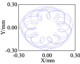
b)= 14670 N/m
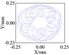
c)= 20777 N/m
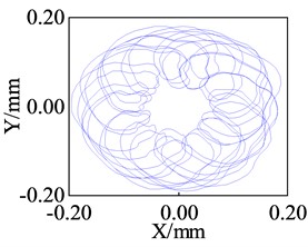
d)= 31667 N/m
5. Conclusions
The nonlinear dynamics of the vertical rotor system were modeled and the effect of the support stiffness on the amplitude-frequency response and non-linear dynamics was numerically analyzed and compared with experimental studies to conclude that:
1) The pivot support stiffness has little effect on the first two orders of critical speed of the rotor system, but it will increase the 3rd order critical speed with little change in the resonance peak. When the speed is between 0 and 550 r/s, the rotor vibrates at the same frequency; when the speed exceeds 550 r/s, the system spectrum has 1/3 times the low frequency in addition to the rotational frequency, and the amplitude of the low frequency gradually increases with the increase of the speed; when the system speed reaches 675 r/s, i.e., in the high-speed area, the amplitude of the low frequency even exceeds the amplitude of the rotational frequency at the same frequency and dominates.
2) As the support stiffness increases, the radius of the shaft trajectory gradually decreases; that is, the amplitude of the low-frequency vortex decreases from 0.35 mm to 0.18 mm, a reduction of 51 %, but the “width” of the low-frequency vortex gradually increases in the form of a percentage. From the point of view of reducing the amplitude of the low-frequency vortex, increasing the stiffness of the elastic pivot has a positive effect. This suggests that using a more rigid flexible pivot is an effective way to reduce low-frequency vortex in the high-speed region.
3) When the support stiffness is in the range of 20,000 N/m to 30,000 N/m, the motion of the lower end of the rotor appears in the form of alternating cycles1 →proposed period. Compared to a pivot stiffness of 10,000 N/m, when the rotor shows a large amplitude of the proposed cycle motion, the corresponding speed is delayed from 550 r/s to 650 r/s, indicating that the higher pivot stiffness extends the stable operating speed range of the rotor.
4) In order to verify the effect of different pivot support stiffness on the dynamic characteristics, machining tests were performed on the elastic pivots of four different journals. By comparing the theoretical and experimental values of the three-dimensional spectra and shaft trajectories, the agreement is good, indicating that the kinetic model is reasonable.
References
-
A. Nishimura, T. Inoue, and Y. Watanabe, “Nonlinear analysis and characteristic variation of self-excited vibration in the vertical rotor system due to the flexible support of the journal bearing,” Journal of Vibration and Acoustics, Vol. 140, No. 1, pp. 1–13, Feb. 2018, https://doi.org/10.1115/1.4037520
-
M. F. White, E. Torbergsen, and V. A. Lumpkin, “Rotordynamic analysis of a vertical pump with tilting-pad journal bearings,” Wear, Vol. 207, No. 1-2, pp. 128–136, Jun. 1997, https://doi.org/10.1016/s0043-1648(96)07469-8
-
V. F. Ovchinnikov, M. Y. Nikolaev, and V. N. Litvinov, “Dynamics of a vertical flexible rotor on active magnetic bearings with structural deviations during seismic disturbances,” IEEE Magnetics Letters, Vol. 9, No. 9, pp. 1–5, 2018, https://doi.org/10.1109/lmag.2018.2852279
-
Jean-Claude Luneno, J. Aidanpää, and R. Gustavsson, “Experimental verification of a combi-bearing model for vertical rotor systems,” Journal of Vibration and Acoustics, Vol. 135, No. 3, pp. 1–5, 2013.
-
G. M. Yang, X. Z. Zhang, and J. P. Dong, “Influence of the lateral connection stiffness of the bearing pair on the stability of the centrifuge,” (in Chinese), Journal of Tsinghua University: Science and Technology, Vol. 48, No. 8, pp. 1279–1282, 2008, https://doi.org/10.16511/j.cnki.qhdxxb.2008.08.014
-
Z. G. Li, J. P. Dong, and X. Z. Zhang, “Dynamic behavior of a vertical rotor with a lower supporting friction pair sliding relative to each other,” (in Chinese), Journal of Tsinghua University: Science and Technology, Vol. 45, No. 6, pp. 817–820, 2005, https://doi.org/10.16511/j.cnki.qhdxxb.2005.06.026
-
Z. G. Li, J. P. Dong, and J. S. Long, “Effect of small shaft friction on centrifuge rotor behavior,” (in Chinese), Journal of Vibration Engineering, Vol. 17, pp. 46–50, 2004, https://doi.org/10.3969/j.issn.1004-4523.2004.z1.014
-
X. Wang, “Vibration characteristics analysis of rotor-bearing system of sliding ball bearing under non-rigid connection,” (in Chinese), in 9th National Conference on Vibration Theory and Applications, pp. 231–232, 2007.
-
T. W. Wu, “Influence of bearing friction and weapon dynamic response characteristics of flexibly supported rotor,” (in Chinese), Atomic Energy Science and Technology, Vol. 54, No. 4, pp. 715–724, 2020.
-
M. Y. Wang, “Numerical study on effect of bearing contact on vibration of rotor system,” (in Chinese), in Annual Conference of China Nuclear Society, Vol. 4, pp. 64–72, 2021.
-
X. J. Dai, J. P. Dong, and X. Z. Zhang, “Effects of unbalances on the rotor/stop rubbing,” (in Chinese), Journal of Mechanical Engineering, No. 6, pp. 90–98, 2001.
-
X. Dai, X. Zhang, and X. Jin, “The partial and full rubbing of a flywheel rotor-bearing-stop system,” (in Chinese), International Journal of Mechanical Sciences, Vol. 43, No. 2, pp. 505–519, Feb. 2001, https://doi.org/10.1016/s0020-7403(99)00121-6
-
X. Dai, Z. Jin, and X. Zhang, “Dynamic behavior of the full rotorstop rubbing: numerical simulation and experimental verification,” (in Chinese), Journal of Sound and Vibration, Vol. 251, No. 5, pp. 807–822, Apr. 2002, https://doi.org/10.1006/jsvi.2001.3998
-
X. J. Dai, C. L. Tang, and S. Q. Yu, “Measuring friction coefficient of the high-speed pivot bearing in oil-bath lubrication by a varying load method,” (in Chinese), Tribology, Vol. 31, No. 1, pp. 7–11, 2011, https://doi.org/10.16078/j.tribology.2011.01.010
-
P. Yu and G. Chen, “Nonlinear modal analysis and its application on prediction of resonance speed for a rotor-stator rubbing system,” (in Chinese), Journal of the Brazilian Society of Mechanical Sciences and Engineering, Vol. 43, No. 4, pp. 1–20, Apr. 2021, https://doi.org/10.1007/s40430-021-02918-5
-
J. Li, Y. Li, F. Zhang, and Y. Feng, “Nonlinear Analysis of Rod Fastened Rotor under Nonuniform Contact Stiffness,” (in Chinese), Shock and Vibration, Vol. 2020, No. 5, pp. 1–10, Dec. 2020, https://doi.org/10.1155/2020/8851996
-
Y. J. Qiu, “Research on dynamics of energy storage flywheel rotor – bearing – damper system,” (in Chinese), Southeast University, Nanjing, 2019.
-
H. Wang and Z. Du, “Dynamic analysis for the energy storage flywheel system,” (in Chinese), Journal of Mechanical Science and Technology, Vol. 30, No. 11, pp. 4825–4831, Nov. 2016, https://doi.org/10.1007/s12206-016-1001-0
-
Y. Qiu and S. Jiang, “Suppression of low-frequency vibration for rotor-bearing system of flywheel energy storage system,” (in Chinese), Mechanical Systems and Signal Processing, Vol. 121, pp. 496–508, Apr. 2019, https://doi.org/10.1016/j.ymssp.2018.11.033
-
Z. Youfeng, L. Xinhua, W. Qiang, W. Zibo, and Z. Hongyu, “Nonlinear modeling and simulation of flywheel energy storage rotor system with looseness and rub-impact coupling hitch,” (in Chinese), International Journal of Nonlinear Sciences and Numerical Simulation, Vol. 23, No. 1, pp. 15–33, Feb. 2022, https://doi.org/10.1515/ijnsns-2019-0110
-
W. G. Yang, D. Gan, T. J. Zhu, and Etc., “The low frequency vibration fault analysis of gas turbine generator unit caused by tilting pad bearing failure,” (in Chinese), Gas Turbine Technology, Vol. 32, No. 1, pp. 63–67, 2019, https://doi.org/10.16120/j.cnki.issn1009-2889.2019.01.013
-
Y. L., Y. Z. Li, X. Y. Tai, and Etc., “Characteristic analysis of looseness-rubbing coupling fault in rotor-sliding-bearing system,” (in Chinese), Journal of Vibration Engineering, Vol. 29, No. 3, pp. 549–554, 2016, https://doi.org/10.16385/j.cnki.issn.1004-4523.2016.03.022
About this article

This work was supported by Science and Technology on Particle Transport and Separation Laboratory Foundation (Grant Number: S7P7S202111, QT210013), Beijing Information Science and Technology University Foundation (Grant Number: 2021XJJ07), the Science and Technology Program of the Beijing Municipal Education Commission (Grant Number: KM201911232007).
The datasets generated during and/or analyzed during the current study are available from the corresponding author on reasonable request.
Qirui Liu: Data analysis and Writing. Changliang Tang: Formal analysis and Validation. Tingwei Wu: Methodology. Yujie Bai: Methodology.
The authors declare that they have no conflict of interest.
