Abstract
Experimental studies of the vertical rotor with the automatic balancer ball type with a torus-shaped body with a cross section of the round form showed that the compensating masses are not accelerated to its operating speed at the each start of the rotor. The work is devoted to clarify the effect of the stiffness of the rotor elastic suspension on the acceleration process of compensating mass.
1. Introduction
One of known methods for reducing vibration of an unbalanced rotating rotor is installation the automatic balancer with compensating masses in the form of balls on the rotor. The automatic balancer can reduce the vibrations of the rotary machine behind the resonance zone. At the same time, the initial conditions for compensating masses need to be established for the acceleration of the compensating masses to the rotor rotation speed in the automatic balancer with torus-shaped body [1].
There are studies [2] in which states that if the compensating masses don’t have initial conditions, they are steadily moving in relative torus-shaped body (unbalanced conditions of the automatic balancer), and cause a rise in the rotor vibration. Works [3, 4] are devoted to the study of the construction and stability of the autobalancing regime depending on the parameters of viscous friction in the automatic balancer and in the suspension of the rotor systems with a horizontal axis of rotation. It is therefore of interest to determine the impact of the settings of the elastic-dissipative rotor suspension on the work of the self-balancing torus-shaped device with a vertical axis of rotation in the acceleration regime of compensating masses. The research results may be used when designing an elastic suspension of rotor systems with an automatic balancer having a torus-shaped body.
The purpose of the paper is to define the required initial conditions for compensating masses to guarantee their acceleration to the rotor speed and their stop with respect to the torus-shaped body of the automatic balancer. The paper is a continuation of papers [1, 5] and is based on experimental tests of centrifuge [6].
2. The design model and mathematical model of the rotor with the automatic balancer
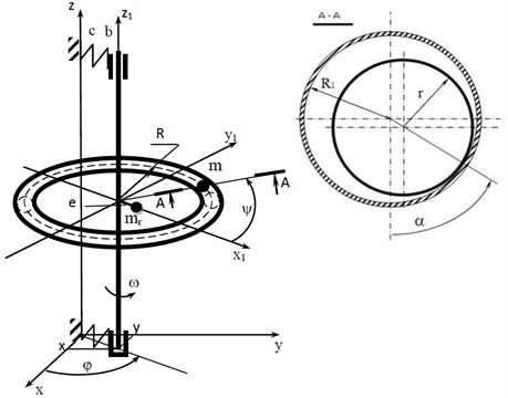
This paper describes the symmetrical vertical rigid rotor on the elastic-dissipative suspension and with the automatic balancer. The automatic balancer body is formed with a toroidal shape with the radius along an average perimeter and radius in cross-section, in which one compensating mass of the ball shape with radius and the mass is placed. The rotor with mass has a static imbalance with value. The rotor is mounted on the elastic-dissipative suspension, which stiffness and viscous damping coefficients are equal to and , respectively. The automatic balancer body is concentrically mounted on the rotor and rotates with an angular velocity .
The Fig. 1 shows the design model of the rotor with the automatic balancer.
Regarding the fixed coordinate system, the rotor together with the automatic balancer body performs the plane-parallel motion described by the rotor axis motion (, coordinates). The compensating masse motion is described by two angular coordinates in the mobile coordinate system (, coordinates).
The system of motion differential equations describing the motion of the rotor system with automatic balancer are given in [1] and are as follows:
Fig. 1The design model of the rotor with the automatic balancer
Given the fact that the rotor rotation speed is constant (, ), and for the convenience of the numerical solution of equations [1], it is represented in the dimensionless form, expressing the system parameters in the following values:
where – nondimensional time. In the numerical solution of differential equations, 1 and 1 are specified:
where – dimensionless force of the ball normal pressure on the inner surface of the automatic balancer body:
The results of the calculation of differential system Eq. (3) are obtained in the form of the dimensionless speeds and coordinates:
3. Research results of the mathematical model
Differential equations of motion Eqs. (1-4) of the rotor system with the automatic balancer have been studied with using of the SPRING program [7], with which it is possible to carry out calculations, both in the operation and transient regimes of the automatic balancer.
Table 1The initial speed of the compensating mass in the circumferential direction of the balancer v3
0.004 | 0.050 | 0.053 | 0.060 | 0.070 | 0.075 | 0.080 | 0.300 | 0.500 | 0.700 | |
0.0024 | –0.655 | –0.360 | –0.351 | –0.331 | –0.305 | –0.293 | –0.281 | –0.108 | –0.095 | –0.073 |
0.0035 | –1 | –1 | –0.658 | –0.599 | –0.551 | –0.531 | –0.513 | –0.141 | –0.109 | –0.086 |
0.0040 | –1 | –1 | –1 | –1 | –1 | –0.650 | –0.609 | –0.184 | –0.114 | –0.091 |
This paper describes the impact of the stiffness coefficient of the rotor elastic suspension on the acceleration conditions of the compensating mass to the rotor rotation speed. At the same time, the initial speed of the compensating mass in the circumferential direction of the balancer was determined (at ; ; ), at which its acceleration is provided to the working speed of the rotor. The calculation results are shown in Table 1, on the basis of which the diagrams of dependence of the initial speed of the compensating mass in the circumferential direction of the automatic balancer body on the value of the p dimensionless stiffness of the rotor suspension at different values of the dimensionless coefficient of rolling friction have been constructed. The diagrams are shown in Fig. 2, which shows that the acceleration of the compensating mass (CM) is significantly affected by the stiffness coefficient of the rotor elastic suspension. By increasing the suspension stiffness (“” option), it is necessary to increase the initial speed of the compensating mass for its acceleration to the operating speed of the rotor.
Fig. 2The dependence diagram of the initial speed of the compensating masses in the circumferential direction of the v3 automatic balancer body on the value of the dimensionless stiffness of the p rotor suspension at different values of the kr dimensionless coefficient of rolling friction
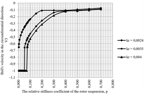
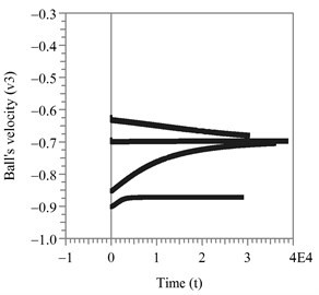
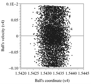
Fig. 3a) The relative speed of the compensating masse in the circumferential direction at changing the initial conditions; b) the phase portrait of the motion of the compensating mass in the transverse plane
a)
b)
Fig. 4The amplitudes of the oscillation of the rotor axis in the steady motion of the compensating mass relative to the automatic balancer body: a) x1 amplitude; b) x2 amplitude
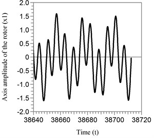
a)
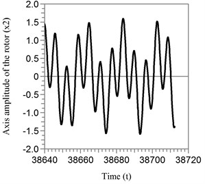
b)
In the regime of continuous motion of the compensating mass relative to the automatic balancer body in the circumferential direction, the ball is accelerated to the intermediate speed, which is stable. As an example, the case has been considered where the relative stiffness coefficient of the rotor suspension is 0,005, and the relative coefficient of rolling friction is 0,0024. The calculation results are presented in Fig. 3, from which it follows that it cannot be accelerated to the working speed of the rotor at the nonsufficient initial speed of the compensating masse, and moves steadily in the circumferential direction of the automatic balancer body. In cross-section the compensating mass makes chaotic oscillations around the equilibrium position 1,543 rad at relatively low speeds.
The rotor axis oscillates with high amplitudes, which are shown in Fig. 4. The Fig. 5 shows the dimensionless amplitudes of the rotor in the working regime of the automatic balancer.
Fig. 5The amplitudes of the oscillation of the rotor axis in the working regime of the automatic balancer: a) x1 amplitude; b) x2 amplitude
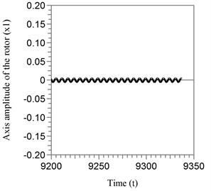
a)
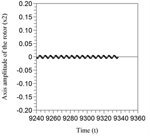
b)
4. Conclusions
Based on the results of the calculations of the mathematical model of the vertical rotor with the automatic balancer with torus-shaped body and cross section of a circle that concentrically mounted thereon, it was found that the acceleration of the compensating mass of the automatic balancer to the operating speed of the rotor essentially depends on the stiffness coefficient of the rotor elastic suspension. At the same time, the more the stiffness coefficient (the closer the operating frequency of the rotor to its own frequency of the system), the more the initial speed of the compensating mass for its acceleration to the rotor speed. Otherwise, the compensating mass steadily moves within the automatic balancer body and the rotor axis varies with high amplitudes.
References
-
Strautmanis G., Mezitis M., Strautmane V. Model of vertical rotor with a ball-type automatic balancer. Vibroengineering Procedia, Vol. 8, 2016, p. 57-62.
-
Strautmanis G., Grinevich I., Strautmane V. The influence of automatic equalizer and rotor parameters on the ball’s motion mode. Mechatronic Systems and Material: Selected Papers, Opole University of Technology, Poland, Opole, 2015, p. 135-141.
-
Olausson Stefan, Hagglund Anders, Wierzba Paul Cost Effective and Reliable Automatic Balancer for High Speed Applications. Patent 2002/0056338 A1 US, Appl. No. 60/216,152, 2002.
-
Gorbenko A. Analytical determination of the stability movement boundaries of the Jeffcott rotor with multi-bodies autobalancer. Vibroengineering Procedia, Vol. 8, 2016, p. 152-157.
-
Bušs D. Assessing steam locomotive dynamics and running safety by computer simulation. Transport Problems, Vol. 10, 2015, p. 15-27.
-
Strautmanis G., Jurjevs V., Cokalo V. Veļas Mazgājamo Mašīnu Centrifūgu Balansēšanas Ierīce. LV Patents, LV 14368 B, 2011.
-
Ščukins I., Zakrževskis M., Ivanov Y., et al. Application of software SPRING and method of complete bifurcation groups for the bifurcation analysis of nonlinear dynamical system. Journal of Vibroengineering, Vol. 10, Issue 4, 2008, p. 510-518.
Cited by
About this article

