Abstract
In the paper, differential equations of motion are derived for a plane model of rotor on anisotropic viscoelastic supports, which is balanced by a ball (roller) or pendulum auto-balancer. The forces of gravity and viscous resistance to the motion of compensating cargoes are taken into account. Cases of an unbalanced rotor motion from engine torque with a variable and constant angular velocity are considered. Using a comparative analysis of the motion equations structure it is established cases in which it is possible to build a unified theory of the specified auto-balancer types and apply the results obtained for one auto-balancer type to other types.
1. Introduction
Passive auto-balancers (AB) of ball (roller) and pendulum types are used to balance fast-rotating rotors during their motion, see, for example, [1]. Under certain conditions, the compensating cargoes (cargoes) in these AB come to a position in which the rotor is balanced and then rotates with it as one rigid whole, until the rotor balance changes or other perturbations appear in the system.
The most complete information about the auto-balancing process is provided by analytical research results. Therefore, there is a common scientific problem in developing an analytical theory of passive balancing. The problem solution is complicated by the presence of several types of AB.
Nowadays, there are separate studies of both ball (roller) [2-6] and pendulum [7, 8] ABs. For example, within a plane model of rotor on isotropic supports, the following have been studied:
– stability of the auto-balancing mode in the case of a two-ball [4] and a two-pendulum AB [7];
– stuck mode of cargoes in the case of a two-ball [5] and a two-pendulum [8] AB.
The question arises whether the results obtained for one AB type can be transferred to other types, and if it is possible, then in what cases. In the present work, this problem is solved within the framework of a plane model of rotor on anisotropic supports, balanced by a ball (roller) or pendulum AB.
The aim of this work is a comparative analysis of models of a rotor system with AB of ball (roller) and pendulum types in order to identify qualitative differences in the dynamic properties of various AB types.
To build physical and mathematical models of the rotor systems with AB under consideration, elements of the theory of rotor machines with AB [1, 3-9] and classical mechanics [10] are used. Differential equations of systems motion are derived using the theorem on the motion of the center of mechanical system mass and Lagrange’s equations of the second kind.
To get an answer to these questions, the differential equations of motion obtained for different AB types are compared.
2. Comparative analysis of mathematical models of the rotor system
2.1. Mechanical model of the rotor system
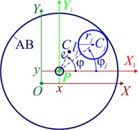
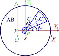
The rotor system (Fig. 1(a)) consists of a rotor of mass and a passive AB – ball, roller (Fig. 1(b)) or pendulum (Fig. 1(c)) type. The rotor is mounted with an eccentricity e on an absolutely rigid shaft. AB is mounted on the shaft. The rotor performs plane-parallel (flat) motions, and its axis is inclined to the horizon by an angle α.
Let’s draw two fixed mutually perpendicular axes , from the position of the static equilibrium of the shaft center, point O. The axes , Y form the right coordinate system, and the axis is horizontal. The movable auxiliary axes , come out from the shaft center, point P, and are parallel to the axes , .
The rotor located on two viscoelastic supports with stiffness and viscosity coefficients in the direction of the axes , – , and , , respectively. The rotor is driven by the engine torque .
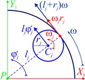
Fig. 1Plane model of the rotor on anisotropic supports and multi-mass AB: a) rotor support diagram; b) kinematics of the motion of the rotor and the ball (roller); c) kinematics of the motion of the rotor and the pendulum; d) rolling without sliding of the ball (roller)
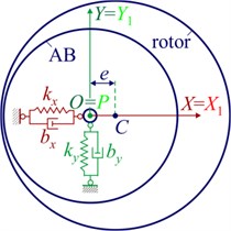
a)
b)
c)
d)
During motion, the shaft (point P) deviates from the position of static equilibrium (point O) by , and rotates with the rotor by an angle .
The AB consists of cargoes. The mass of the -th cargo . The center of mass of the cargo, point , moves along a circle of radius with the center at point P (Fig. 1(b), (c)). The position of the center of mass of the -th cargo relative to the AB housing is determined by the angle . The angle is measured from the axis to the segment .
The AB housing rotates with the rotor around point P at an angular velocity , where the character stroke denotes the time derivative . The segment rotates at an angular velocity .
The motion of the cargo relative to the AB housing is hindered by a viscous resistance force having a module:
where – coefficient of viscous resistance force; – the velocity module of mass center of the cargo number relative to the AB housing.
Balls (rollers) roll along their races without slipping (Fig. 1(d)).
We consider the motion of the ball (roller) number j relative to the AB housing as the sum of the translational motion with the center of mass at the velocity and the rotational motion around the center of mass at an angular velocity . At the point of contact of the ball (roller) with the race, the velocity’s of the ball (roller) and the race are the same: . From here we find:
As it is customary in the analytical theory of passive ABs, we assume that AB cargoes do not interfere with each other’s motion [1, 3-9].
2.2. Mathematical model of the rotor system with a variable rotor speed
We will conditionally divide the differential equations of system motion into the motion equations of the rotor and cargoes.
The theorem on the motion of the center of mass of a mechanical system [10] gives the following differential equations of translational motion of the rotor:
where – mass of the whole system; , – projections of the total imbalance of the rotor and cargoes on the axis , :
It should be noted that:
– gravity is not included in Eq. (3) because of the position of static equilibrium of the shaft center is taken as the origin point;
– system Eq. (3) is a homogeneous system of linear differential equations with constant coefficients relative to unknown generalized coordinates , and , ;
– the form of Eq. (3) does not depend on the AB type.
We compose the remaining motion equations using Lagrange’s equations of the second kind [10].
The system kinetic energy is the sum of the kinetic energies of the rotor and the cargoes :
According to Kőnig’s theorem [10], the kinetic energy of the rotor has two components caused by the translational motion of the rotor with the center of mass (point C) and the rotational motion of the rotor around the center of mass:
where – the velocity module of the center of rotor mass; – axial moment of inertia of the rotor relative to point P (longitudinal shaft axis).
According to Kőnig’s theorem [10], the kinetic energy of the -th AB cargo is equal to the kinetic energy of translational motion together with the center of mass and the kinetic energy of rotation around the center of mass:
where – the velocity module of the mass center of the cargo; – principal central axial moment of cargo inertia; – the module of the angular velocity of cargo rotation around the center of mass.
Kinetic energy of the -th ball (roller):
where – dimensionless coefficient. For the ball , for the roller and, respectively, 1 + 2/5 = 7/5, 1 + 2/5 = 3/2.
The kinetic energy of the -th pendulum, taking into account that :
where .
The kinetic energy of the whole mechanical system is obtained on the basis of Eqs. (5-9):
– in the case of a ball (roller) AB:
– in the case of a pendulum AB:
Potential energy of the system (accurate to a constant):
Rayleigh dissipation function of the system:
The remaining motion equations of the mechanical system elements are obtained using the equations Eqs. (5-13) with the help of Lagrange’s equations of the second kind [10]:
When obtaining the differential equation of rotational rotor motion, it was taken into account that , Then this equation has the form:
– in the case of a ball (roller) AB:
– in the case of a pendulum AB:
When obtaining the differential motion equations of cargoes, it was taken into account that , As a result, the following differential motion equations were obtained:
– balls (rollers) motion equations:
– pendulums motion equations:
Thus, the mathematical motion model of the rotor with AB of a ball (roller) type has the form of the equations system Eqs. (3), (15), (17), and the motion model of the rotor with AB of a pendulum type has the form of the equations system Eqs. (3), (16), (18). Both of these models correspond to a variable rotor speed.
A comparative analysis of models of the rotor system with AB shows the following. The form of the differential equations of rotational motion of the rotor and the motion of cargoes depends on the type of AB, see Eqs. (15), (17) and, accordingly, Eqs. (16), (18). Eqs. (15), (17) contain additional terms proportional to the angular accelerations of the rotor and cargoes.
Therefore, for a variable rotor speed , it is impossible to build a unified theory of the considered AB types. Such a theory studies the modes of acceleration and braking of the rotor, as well as other modes associated with a change in the speed of rotor rotation.
2.3. Mathematical model of the rotor system when the rotor rotates at a constant angular velocity
Let the rotor rotate with a constant angular velocity and the angle of rotor rotation is equal to . With this in mind, from Eqs. (3), (15), (17) and from Eqs. (3), (16), (18) we obtain the following differential equations of system motion:
– rotor motion equations:
– cargoes motion equations:
Thus, in the case of const, the form of the motion Eqs. (19), (20) does not depend on the type of AB. Therefore, it is possible to build a unified theory of the considered types of ABs when the rotor rotates with a constant angular velocity. Such a theory includes: the theory of the existence and stability of the main (in which the cargoes rotate synchronously with the rotor) and secondary system motions; the theory of stuck mode of cargoes in the AB.
3. Conclusions
A comparative analysis of the structure of motion models of the rotor system with AB showed the following.
1) When the rotor rotates at a variable speed, the equations of system motion for ball (roller) AB are fundamentally different from the equations of motion for pendulum AB. The difference is caused by the fact that the pendulum can rotate freely relative to the rotor, and the balls (rollers) roll without sliding along the circular paths that are rigidly connected to the rotor. Therefore, for , ball (roller) ABs have dynamic properties that fundamentally differ from ABs of a pendulum type, specifically: the angular accelerations of cargoes (balls or rollers) and a rotor have a mutual influence on their motion, which is not observed in ABs of a pendulum type.
For the specified modes of rotor motion, it is impossible to build a unified theory for ball (roller) and pendulum ABs.
2) When the rotor rotates at a constant speed, the form of the motion equations of the system does not depend on the type of AB. In this case, it is possible to build a unified theory of ball (roller) and pendulum ABs. Therefore, the results obtained previously for one type of AB are applicable for another type of AB.
References
-
Fіlіmonіhіn G. B. Balancing and Vibration Protection of Rotors by Autobalancers with Solid Corrective Weights. Kirovograd, KNTU, 2004, p. 352, (in Ukrainian).
-
Gorbenko A. N. On the stability of self-balancing of a rotor with the help of balls. Strength of Materials, Vol. 35, Issue 3, 2003, p. 305-312.
-
Chung J. Effect of gravity and angular velocity on an automatic ball balancer. Proceedings of the Institution of Mechanical Engineers, Part C: Journal of Mechanical Engineering Science, Vol. 219, Issue 1, 2005, p. 43-51.
-
Lu Chung-Jen, Wang Ming-Cheng, Huang Shih-Hsuan Analytical study of the stability of a two-ball automatic balancer. Mechanical Systems and Signal Processing, Vol. 23, Issue 3, 2009, p. 884-896.
-
Lu Chung-Jen, Tien Meng-Hsuan Pure-rotary periodic motions of a planar two-ball auto-balancer system. Mechanical Systems and Signal Processing, Vol. 32, 2012, p. 251-268.
-
Strautmanis G., Mezītis M., Strautmane V., Gorbenko A. On the issue of impact of anisotropy of the rotor elastic suspension on the performance of the automatic balancer. Vibroengineering Procedia, Vol. 17, Issue 1, 2018, p. 1-6.
-
Dubovik V. A., Ziyakaev G. R. The basic motion of pendulum auto-balancers on flexible shaft with resilient supports. News of Tomsk Polytechnic University, Vol. 317, Issue 2, 2010, p. 37-39, (in Russian).
-
Artyunin A. I. The “sticking” effect and the characteristics of the rotor movement with pendulum auto-balancers. Science and Education: the Electronic Scientific Publication of the Bauman NSTU, Vol. 8, 2013, p. 443-454, (in Russian).
-
Goncharov V. V., Filimonikhin G. B. Form and structure of differential equations of motion and process of auto-balancing in the rotor machine with auto-balancers. Bulletin of the Tomsk Polytechnic University, Geo Assets Engineering, Vol. 326, Issue 12, 2015, p. 20-30.
-
Strauch D. Classical Mechanics: An Introduction. Springer-Verlag Berlin Heidelberg, 2009, p. 405.
About this article

