Abstract
Among the ways to reduce vibrations of rotary machines with a vertical or horizontal axis of rotation is the use of ball-type automatic balancing devices. At the same time, the acceleration of compensating masses in the automatic balancing device with an annular cross-section of the housing showed that to accelerate the compensating masses to the operating speed of the rotor, it is necessary to provide the initial velocity due to the influence of gravity at the initial stage of acceleration. The value of the initial velocity of compensating masses depends on the parameters of the elastic suspension of the rotor, the size of the compensating mass, the coefficient of rolling friction between the compensating mass and the inner surface of the housing of the automatic balancing device and other parameters. In this work, the influence of the rolling friction coefficient and other parameters of the rotor system on the acceleration of compensating masses is studied, recommendations on the selection of parameters are given.
1. Introduction
A ball-type automatic balancing device (ABD) makes it possible to reduce the imbalance of the rotating unbalanced rotor on an elastic suspension in the super resonant frequency band. The most effective, in terms of sensitivity, is an ABD with a torus-shaped housing with an annular cross-section, in which ball-shaped compensating masses (CM) freely move. However, the acceleration of the compensating masses to the rotor speed depends on many parameters of the rotor system, among which are the stiffness of the elastic rotor suspension, the rolling friction coefficient of the CM on the internal surface of the ABD’s housing, etc. [1].
At the same time, in certain cases, it is necessary to provide the initial speed [2] to accelerate the compensating masses of the ABD, otherwise the CMs stably move relative to the ABD’s housing (unsteady operating mode), which leads to increased rotor vibrations. In [3-5], the designs and stability of the automatic balancing mode are considered depending on the parameters of viscous friction in the ABD and in the suspension of the rotor system with a horizontal axis of rotation. Therefore, it is of interest to determine the influence of the parameters of the elastic-dissipative rotor suspension on the performance of a torus-shaped automatic balancing device with a horizontal axis of rotation in the mode of CM’ acceleration. The results of the study can be used in the design of elastic suspension of rotary systems with ABDs, having a toroidal shape of the housing.
The aim of the work is to study the process of acceleration of CM of ABD mounted on a horizontal rotor with an elastic-dissipative suspension. At the same time, the conditions for reliable acceleration of the CM to the operating speed of the rotor were determined. The work is a continuation of [1, 4] and is based on experimental tests of rotors with an ABD [6, 7].
2. Design model and mathematical model of a rotor with an ABD
The paper deals with a symmetrical horizontal rigid rotor on an elastic-dissipative suspension with the ABD’s housing concentrically mounted on it. The ABD’s housing is torus-shaped with radius along the middle circumference and in cross section, into which one ball-shaped compensating mass of radius and mass is placed. The rotor with mass has a static eccentricity of value. Rotor suspension parameters: stiffness coefficient and viscous damping and , respectively. The ABD’s housing, together with the rotor, rotates related to an axis with angular velocity .
The design model of the rotor with ABD is shown in Fig. 1.
Fig. 1Design model of the rotor system with an ABD with a horizontal axis of rotation
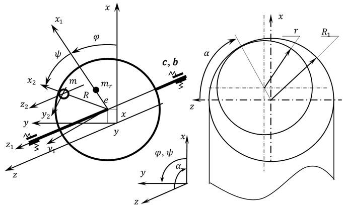
The velocity of the rotor rotation is assumed constant (, ) The dimensionless parameters of the rotor system have the following form and values:
where – dimensionless time;
The mathematical model of the rotor system in a dimensionless form, describing its movements, consists of four differential equations:
where is the dimensionless force of the normal pressure of the ball on the inner surface of the ABD’s housing:
The results of the calculation of the system of differential Eqs. (1)-(4) are obtained in the form of dimensionless velocities and coordinates:
3. Results of the study of the mathematical model
Differential equations of motion Eqs. (1)-(4) of the rotor system with an ABD have been investigated by means of software SPRING [8]. The authors research the impact of CM size and stiffness of elastic rotor suspension on conditions of CM’ acceleration to the rotor rotation speed. At the same time, the limiting smallest initial speed of the CM in the circumferential direction of the ABD, which provides its acceleration to the operating speed of the rotor, has been determined.
The calculation of the model has been made in two stages. At the first stage, the influence of rolling friction in the ABD on the acceleration of the CM is determined. In this case, the acceleration of the CM is considered for four values of the rolling friction coefficient, which correspond to its possible values when the steel ball moves along the steel ( 0,00002 m; 0,00003 m; 0,00004 m; 0,00005 m). The calculation is carried out at fixed values of the coefficient of relative stiffness and dissipation in the rotor suspension ( 0,005; 0,145; 0,055). In this case, the following dimensionless parameters of the rotor system were accepted: 0,005; 2,5; 15; 200; 0,5005. Based on the calculations in Fig. 2 and Fig. 3, the graphs of the dependence of the limiting smallest initial velocity of CM in the circumferential direction of the ABD’s housing on the value of the dimensionless gap between the ABD’s housing and the CM in cross section, have been plotted.
It follows from the graphs (see Fig. 2(a)) and (b)) that reducing the value of the dissipation coefficient of the rotor suspension reduces the required minimum initial velocity of the compensating mass for its acceleration to the operating speed of the rotor. The value of the smallest initial velocity decreases also with an increase in the gap between the CM and the ABD’s housing in cross section. However, from the graphs, it follows that for a horizontal rotor with an ABD, in which only the rolling friction force acts between the CM and the ABD’s housing, it is not possible to accelerate the CM from the standstill.
At the second stage of the study, graphs were plotted of the dependence of the required minimum initial speed of CM in the circumferential direction of the ABD’s housing on the dimensionless gap between the ABD’s housing and CM in cross section for various values of the relative stiffness of the elastic rotor suspension (from 0,003 to 0,037) at various values of the relative dissipation coefficient ( 0,145) for two fixed values of the rolling friction coefficient in the ABD ( 0,00002 m and 0,00005 m). The remaining parameters of the rotor system did not change.
The results of the study are shown in Fig. 3.
Fig. 2The graphs of the dependence of the required minimum initial speed of the CМ ψ¯˙ in the circumferential direction of the ABD’s housing on the size of the dimensionless gap between the CM and the housing of the ABD at different values of rolling friction: 1 – k= 0,00002 m, 2 – k= 0,00003 m, 3 – k= 0,00004 m, 4 – k= 0,00005 m for two values of the dissipation coefficient in the rotor suspension: a) n= 0,145, b) n= 0,055
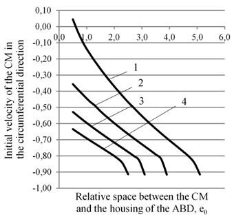
a)
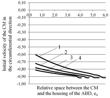
b)
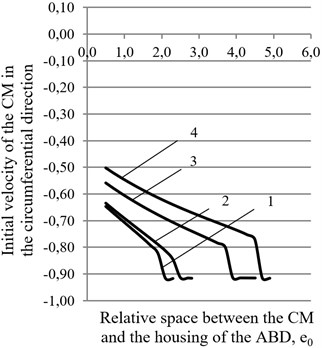
Fig. 3Graphs of the dependence of the required smallest initial speed of the CM ψ¯˙ in the circumferential direction of the housing of the ABD on the size of the dimensionless gap between the CM and the housing of the ABD at different values of the rotor suspension: 1 – p= 0,003, 2 – p= 0,005, 3 – p= 0,021, 4 – p= 0,037 for two values of rolling friction coefficient: a) k= 0,00002 m, b) k= 0,00005 m
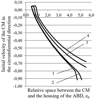
a)
b)
From the analysis of Fig. 3 it follows that when the stiffness of the rotor suspension increases, the required smallest initial velocity of the CМ in the circumferential direction of the ABD’s housing increases. At the same time, there is a tendency to decrease the initial speed of the CM at an increase in the gap between the housing and the CM in the cross section of the ABD. However, just as in the previous case, it is not possible to accelerate the CM from the standstill. At any value of the gap between the CM and the housing of the ABD, an initial speed is required to accelerate the CM to the operating speed of the rotor. Based on the conducted research, it is of interest to further study the mathematical model of a rotor system with a horizontal axis of rotation, in which the viscous friction force inside the ABD will be taken into account when accelerating the CM.
It is of interest to study the performance of the ABD with two or more compensating masses and their influence on the rotor motion, as well as their impact interaction during acceleration to the operating rotor speed.
4. Conclusions
As a result of the calculations of the mathematical model of a horizontal rotor with a torus-shaped ABD’s housing concentrically mounted on it and an annular cross section, it was determined that the smallest initial speed of the CM required for its acceleration to the operating speed of the rotor depends on the coefficients of stiffness and the elastic dissipation of the rotor suspension. At the same time, an increase in the stiffness coefficients and dissipation of the elastic rotor suspension increases the required initial absolute speed of the CM in the circumferential direction of the ADD to accelerate it to the rotor speed.
Increasing the gap between the CM and the ABD’s housing in cross section leads to a decrease in the required initial velocity of the corrective masses for their acceleration, however, when only rolling friction forces act on the CM, this does not provide for the CM’ acceleration from the standstill. To ensure the efficiency of the ABD at the stage of acceleration of the CM, it is necessary to increase the friction force between the housing of the ABD and the compensating mass.
It is of interest to further continue the study of the model of a horizontal rotor with an ABD in order to search for additional conditions to ensure the acceleration of the CM from the standstill.
References
-
Strautmanis G., Mezitis M., Strautmane V. The impact of rotor elastic suspension settings on the acceleration of the automatic balancer compensating mass. Vibroengineering Procedia, Vol. 14, 2017, p. 13-17.
-
Strautmanis G., Grinevich I., Strautmane V. The influence of automatic equalizer and rotor parameters on the ball’s motion mode. Mechatronic Systems and Materials 2014: Selected Papers, 2015, p. 135-141.
-
Gorbenko A. Analytical determination of the stability movement boundaries of the Jeffcott rotor with multi-bodies autobalancer. Vibroengineering Procedia, Vol. 8, 2016, p. 152-157.
-
Gorbenko A. N. Influence of gravity on rotor oscillations with a ball self-balancing device. Bulletin of the Technological University of Podolia, Vol. 1, 2000, p. 110-114, (in Russia).
-
Fіlіmonіhіn G.B. Balancing and Vibration Protection of Rotors by Autobalancers with Solid Corrective Weights. Kirovograd, KNTU, 2004, p. 352, (in Ukrainian).
-
Strautmanis G., Jurjevs V., Cokalo V. A Balancing Device for Centrifuges of Washing Mashines. LV patents, LV 14368 B, 2011, (in Latvian).
-
Strautmanis G., Strautmane V., Mezitis M., Gorbenko A. Toroidal Balancing Device for Rotary Units. LV patents, LV 15247 B, 2018, (in Latvian).
-
Ščukins I., Zakrževskis M., Ivanov Y., et. al. Application of software SPRING and method of complete bifurcation groups for the bifurcation analysis of nonlinear dynamical system. Journal of Vibroengineering, Vol. 10, Issue 4, 2008, p. 510-518.
About this article

