Abstract
The effects of tool radial vibration bring not only poor surface quality, inferior dimensional accuracy, but also disproportionate tool wear or tool breakage and excessive noise. Therefore, online measurement and monitoring of tool vibration are necessary. In order to monitor the tool vibration, an optical fiber measurement system was design in this pater. Firstly, the structure and basic principle of the optical fiber sensor was given; secondly, the light intensity to voltage converter circuit was introduced; then, an experiment platform was built for verify the feasibility of the optical measuring system, and the result shows that the radial vibration of a smooth 10 mm diameter shaft can be measured quickly.
1. Introduction
Undesired tool vibrations, whose main sources are environment, process and machine tool, etc., often accompany machining operations [1]. According to the sources, there exist three types of machining vibrations: free vibration, forced vibration, and self-excited vibration [2]. Free vibration occurs because of the collision between the tool and work piece. In CNC milling machine-cutting process, one of the important factors that caused mismachining tolerance is the tool radial vibration, which directly affect the surface geometrical precision and the smallest form errors that under ideal processing conditions. In actual cutting processing, its negative effects mainly include the machining accuracy of parts, roughness of surface, wear nonuniformity of tool and the cutting process characters of multitooth tool. The bigger radial vibration the more unstable tool machining state and bad processing effects. Furthermore, the vibration caused the system under continuous dynamic alternating load, which result of tool rapid erosion (even chipping of the tool), machine connection property damaged, even the cutting processing halt [3].
In order to reduce the vibration, the cutting parameters must be cut down but bring about the reduction of production efficiency. Over the decades, many efforts were made to find the best operating point considering tool vibration and the cutting efficiency and quality. In these work, tool vibration dynamic precision measuring method undoubtedly is one of the important ideas to solve the problems that including tool vibration active control, tool health monitoring and process optimization. For example, Somkiat [4] proposed a method by taking the ratio of the average variances of the dynamic cutting forces of three force components, to identify the chatter. Uquillas [5] designed a new smart tool holder uses wireless technology to transmit the measurement data for monitoring by analyzing the frequency spectrum of the cutting force in stable cutting and in chatter. Many sensors such as touch sensors, power sensors, acoustic emission sensors [6, 7], vibration sensors, torque sensors, force sensors, vision sensors and so on were adopted for tool condition monitoring [8]. With the development of optical fiber sensor technology, Optical fiber sensors are increasingly used in actual engineering application because of the nonelectrical nature of signals [9]. Prokopczuk K. [10] presents an optical fiber sensor for membrane sub-micrometer vibration measurement; Wang [11] proposed a composite optical fiber sensor for the distributed vibration measurement. To realize the dynamic precision measurement of the cutter radial vibration, an intensity modeled optical fiber displacement sensor was design in this paper. The measurement system was build. Therefore, the experiment platform with a smooth 10 mm diameter shaft was built for verify the feasibility of the optical measuring system.
2. Tool radial vibration optical fiber measurement system
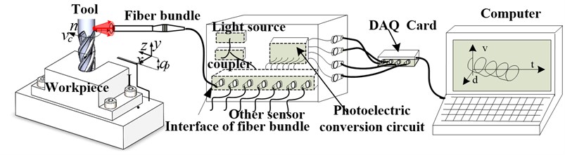
As Fig. 1 shown, the tool radial vibration optical fiber measurement system mainly consists of six parts; which including an optical fiber bundle (based on the reflective intensity modulated principle), the light source (650 nm red light), the photoelectric conversion circuit, the DAQ Card and a computer with data stored and analysis software. In the tool radial vibration measurement process, the light shoot out from the middle embittering fiber (EF), then the reflective light be received by the received fibers (RF) and transmit to the photoelectric conversion chip; the light signal was been converted to voltage signal after photoelectric conversion, and captured by the DAQ card, lastly, stored and displayed by the computer.
Fig. 1The schematic diagram of tool vibration optical fiber measurement system
2.1. Sensor structure
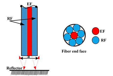
The structure of the optical fiber bundle shown as Fig. 2. The structural parameters of the optical fiber have impenitent effect on sensor characteristics, such as the core diameter of fiber, NA, the axis spacing of receiving fiber and emitting fiber. Recent years, the model of light intensity displacement sensor established based on a variety of assumptions [12, 13]. According to the character of tool radial vibration, the circle coaxial optical fiber bundle probe was designed base on the reflective intensity principle, as Fig. 2 shown, it was consisted of the emitting fiber (1 fiber, EF) and the receiving fibers (6 fibers, RF).
Fig. 2Arrangement of the fiber bundle
2.2. Sensor principle and design parameters
As many others did [12], the light intensity distribution of the optical field end can be expressed as [13, 14]:
Eq. (1) is closer to the real situation based on practice and theoretical analysis. where, is the optical field end luminous flux density which location at ; is the light loss of the optical fiber in the optical transmission processing; is the light strength coupled in to the fibers that form the light source. is the optical field distribution equivalent radius, and:
where, is the parameter related to the optical fiber refractive index; is the radius of the receiving fiber; is the parameters related to fiber coupling characteristics; is the maximum exit angle of the fiber. According the equation [12, 13] others research did, the RF received light intensity curve can be gained, as Fig. 3 shown.
Based on the simulation, the basic design parameter shown as Table 1.
Fig. 3The receiving light intensity changing curve with the displacement between the tool surface and the fiber probe changing
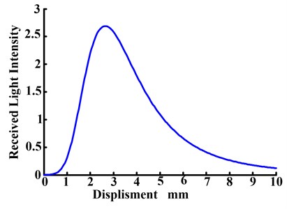
Table 1Optical fiber bundle design parameters
Parameters | Value |
Radius of rf & ef (nucleus) | 150 μm |
Cladding of the fiber | 15 μm |
Na | 0.22 |
Length of the fiber bundle | 1.5m |
Fiber type | Standard multimode optical fiber |
2.3. Measurement circuit
The measurement circuit is shown as Fig. 4. The circuit main consists of the light to voltage chip (OPT 101), the dark error offset circuit and the low-pass filter circuit, which can be seen in Fig. 4. The OPT101 is the main part for collecting the light and convertor the light intensity into corresponding voltage; then, the voltage signals were amplified using the INA118 chip to improve the signal-to-noise ratio and ensure the measurement accuracy.
3. Experiment and results discussion
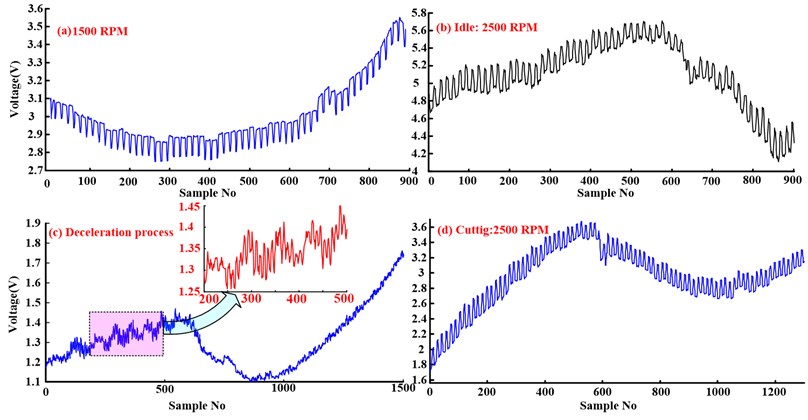
The measurement experiments were carried out under four operating conditions, including the shaft with a speed of idle with a speed of 1500 RPM, idle with a speed of 2500 RPM, simulation cutting with a speed of 2500 RPM and the deceleration process of the shaft. The experiment results shown as Fig. 5. From the results, we can see that with the increase of the platform rotation speed, the shaft radial vibration amplitude increasing at the same time, by contrasting the curve Fig. 5(a) and curve Fig. 5(b) shown in Fig. 5. Contrasting the measurement result of idle speed of 2500 RPM (curve Fig. 5(b)) and cutting speed of 2500 RPM (curve Fig. 5(d)), the vibration reduced significantly, as in the simulation cutting process, most vibrational energy of the shaft was absorbed by the processed parts. What needs to be concerned is that curve Fig. 5(c), in the deceleration process the radial vibration of the shaft is more complicated, which mean that the force of the platform is extraordinary complexity. More information will be obtained by further analysis of the measurement signals.
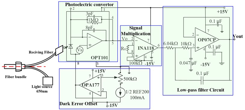
Fig. 4. Light intensity to voltage converter measurement circuit
Fig. 5Experiment results of the tool in different operating condition
4. Conclusions
In order to monitor the tool radial vibration, an optical fiber measurement system was design in this pater. Firstly, the structure and basic principle of the optical fiber sensor was given; secondly, the light intensity to voltage converter circuit was introduced. Then, four operating conditions measurement tests were done, which including the shaft with an idle speed of 1500 RPM, idle with a speed of 2500 RPM, a simulation cutting speed of 2500 RPM and the deceleration process of the shaft. Result shows that the optical fiber tool radial vibration measurement can measured the vibration of the smooth 10 mm diameter shaft quickly. However, the next work should focus on the signal analysis of the measurement results.
References
-
Siddhpura M., Paurobally R. A review of chatter vibration research in turning. International Journal of Machine Tools and Manufacture, 2012, p. 27-47.
-
Muhammad Bashir Bala, Wan Min, Feng Jia, Zhang Wei Hong Dynamic damping of machining vibration: a review. International Journal of Advanced Manufacturing Technology, Vol. 89, Issues 9-12, 2017, p. 2935-2952.
-
Li Jingwei Discussion of vibrating tool phenomenon during deep-hole processing. Coal Technology, Vol. 27, Issue 6, 2008, p. 19-21.
-
Tangjitsitcharoen S., Pongsathornwiwat N. Development of chatter detection in milling processes. The International Journal of Advanced Manufacturing Technology, Vol. 65, Issue 5, 2013, p. 919-927.
-
Uquillas D. A. R., Hsiao T. Wireless tool holder sensor design for cutting force measurement applied to chatter detection. IEEE Region 10 Conference (TENCON), Singapore, 2016, p. 1845-1848.
-
Dimla D. E. Sensors signals for tool-wear monitoring in metal cutting operations – a review of methods. International Journal of Machine Tools and Manufacture, Vol. 40, 2000, p. 1073-1098.
-
Xiaoli Li Development of current sensor for cutting force measurement in turning. IEEE Transactions on Instrumentation and Measurement, Vol. 54, Issue 1, 2005, p. 289-296.
-
Chelladurai H., Jain V. K., Vyas N. S. Development of a cutting tool condition monitoring system for high speed turning operation by vibration and strain analysis. The International Journal of Advanced Manufacturing Technology, Vol. 37, 2008, p. 471-485.
-
Corres M., Goicoechea J. R. Vibration detection using optical fiber sensors. Journal of Sensors, 2010, https://doi.org/10.1155/2010/936487.
-
Prokopczuk K., Rozwadowski K., Starzynska M. D., et al. Optical fiber sensor for membrane submicrometer vibration measurement. Applied Optics, Vol. 53, Issue 26, 2014, p. 6051-6057.
-
Wang et al. Y. Optical fiber vibration sensor using chaotic laser. IEEE Photonics Technology Letters, Vol. 29, Issue 16, 2017, p. 1336-1339.
-
Garcia I., Zubia J., Durana G., et al. Optical fiber sensors for aircraft structural health monitoring. Sensors, Vol. 15, Issue 7, 2015, p. 15494-15519.
-
Jia Binghui, He Lei An optical fiber measurement system for blade tip clearance of engine. International Journal of Aerospace Engineering, 2017, https://doi.org/10.1155/2017/4168150.
-
Jia Binghui, He Lei, Yan Guodong, Feng Yong A differential reflective intensity optical fiber angular displacement sensor. Sensors, Vol. 16, Issue 9, 2016, p. 1508.
Cited by
About this article

This study was supported by the National Natural Science Foundation of China (No. 51405222 and No. 51775260), the Qinglan Project of Jiangsu Province (2017) of China, and the funds of Nanjing Institute of Technology (No. CKJA201601).
