Abstract
This paper provides an improved signal summing method for the spacecraft force limited vibration test system with eight force transducers. The key point for this method is to change the combination way of the signals coming out of the eight force transducers while the formulas inside the signal conditioning amplifier have been used skillfully. This method had been successfully adopted in the spacecraft force limited vibration test and the accuracy requirements of key force and moment signals have been met. And this method has been proved to be a very powerful tool for providing the critical force and moment data used to determine the force limited profile during the spacecraft dynamic test.
1. Introduction
The spacecraft force limited vibration test is implemented by dual control testing where both the interface acceleration and force are controlled during the vibration tests. The force limited vibration test technique has been utilized to provide more realistic vibration test environments for spacecraft and minimize the over-testing problem and differences in flight versus test mounting impedance so that the safety of the spacecraft can be protected [1-3].
During the spacecraft force limited vibration test, several force transducers are usually placed between the spacecraft and fixture to measure the forces and moments which are controlled by the vibration controller. Based on the geometrical information of four force transducers placed rectangularly underneath the spacecraft, the standard force signal conditioning amplifier (Kistler 5080A) available on the market will perform a fast calculation of the six output forces and moments [4-6]. But how to use this amplifier to calculate the major forces and moments for a spacecraft force limited vibration test system with eight force transducers have become a very interestingly technical issue. So, this paper will give a detailed discussion about how to deal with this problem.
2. Standard signal summing method for four force transducers
2.1. Configuration of four force transducers
The force transducers are usually placed between the spacecraft and fixture. Fig. 1 shows the geometrical position of the four force transducers. The coordinate system of these transducers should remain the same. Suppose that the reference frame of the spacecraft is the same as all of the force transducers.
Fig. 1Geometrical position of 4 force transducers
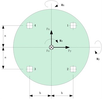
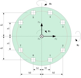
Fig. 2Geometrical position of 8 force transducers
2.2. Parameters setup and output of force and moment signal
Before the spacecraft force limited vibration test, the cables of the force transducers should be connected to the signal conditioner correctly. The second column of Table 1 shows how to connect the cables of force transducers with the signal conditioner.
Table 1Output of force signal conditioner for four force transducers
Output No. | Original cable connection and output | Actual signal name |
Ch01 | ||
Ch02 | ||
Ch03 | ||
Ch04 | ||
Ch05 | ||
Ch06 | ||
Ch07 | ||
Ch08 | ||
Ch09 | ||
Ch10 | ||
Ch11 | ||
Ch12 | ||
Ch13 | ||
Ch14 |
For the first four channels, two force signals coming from two different transducers are combined together and then sent into the input channel of the conditioner. For the last four channels to which the direction signal of each transducers are individually connected.
After the work of the cables connection with the signal conditioner finished, the next step is to set the sensitivities of each channel, the force arm (a & b) and the filtering frequency range. The signal conditioner sends out 14 signals including forces and moments which can be used to completely characterize how much the force inflicted onto the whole spacecraft.
3. Improved signal summing method for eight force transducers
3.1. Configuration of eight force transducers
The geometrical position of the eight force transducers usually placed underneath spacecraft are shown by Fig. 2. One group of force transducers including No. 1 to No. 4 is symmetrical with the other group of transducers which includes No. 8 to No. 5 in descending order. The coordinate system of these transducers should remain the same. Suppose the reference frame of the spacecraft is also the same as the force transducers.
3.2. Parameters setup and output of force and moment signal
While performing the force limited vibration test for spacecraft with eight force transducers, the cables should be connected to the signal conditioner correctly. The second column of Table 2 shows how to connect the cables of force transducers with the signal conditioner for longitudinal direction test. The signal conditioner sends out 14 signals including forces and moments among which only 11 force signals are meaningful and can be used.
Table 2Output of force signal conditioner for longitudinal vibration test (Z)
Output No. | Improved cable connection and output | Actual signal name |
Ch01 | ||
Ch02 | ||
Ch03 | ||
Ch04 | ||
Ch05 | ||
Ch06 | ||
Ch07 | ||
Ch08 | ||
Ch09 | ||
Ch10 | ||
Ch11 | ||
Ch12 | Meaningless | |
Ch13 | Meaningless | |
Ch14 | Meaningless |
The second column of Table 3 and Table 4 shows how to connect the cables of force transducers with the signal conditioner for latitudinal direction test. The signal conditioner sends out 14 signals among which only 12 signals are meaningful and can be used.
Table 3Output of force signal conditioner for latitudinal vibration test (X)
Output No. | Improved cable connection and output | Actual signal name |
Ch01 | ||
Ch02 | ||
Ch03 | ||
Ch04 | ||
Ch05 | ||
Ch06 | ||
Ch07 | ||
Ch08 | ||
Ch09 | ||
Ch10 | ||
Ch11 | ||
Ch12 | Meaningless | |
Ch13 | Meaningless | |
Ch14 |
Table 4Output of force signal conditioner for latitudinal vibration test (Y)
Output No. | Improved cable connection and output | Actual signal name |
Ch01 | ||
Ch02 | ||
Ch03 | ||
Ch04 | ||
Ch05 | ||
Ch06 | ||
Ch07 | ||
Ch08 | ||
Ch09 | ||
Ch10 | ||
Ch11 | ||
Ch12 | Meaningless | |
Ch13 | Meaningless | |
Ch14 |
4. Test setup and validation
4.1. System introduction
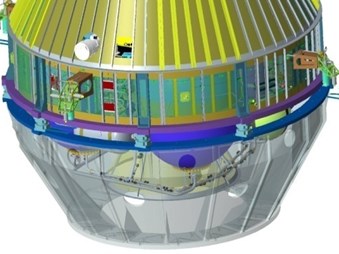
It is shown in Fig. 3 that the force measuring device consists of eight force transducers and a pair of aluminum rings. The 3-component force transducers are mounted between the upper and lower rings to measure both tensile and compression forces in three orthogonal directions. The weight for the spacecraft and the force measuring device is around 5345 kg and 195 kg respectively. The centre of gravity of the spacecraft is about 1.6 m high above the middle surface of the force measuring device. The relations of the coordinate frame for the spacecraft and force transducers are shown by Table 5.
Table 5The coordinate relation between the spacecraft and force transducers
No. | The Coordinate system for the spacecraft | The coordinate system for the force transducers |
1 | (longitudinal) | + |
2 | (latitudinal) | + |
3 | (latitudinal) | - |
Fig. 3The force measuring device mounted between spacecraft and fixture
4.2. The force limited vibration test for the spacecraft
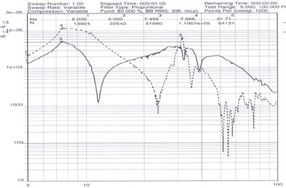
In order to verify the correctness of the improved force summing method, both a low level sine test and a high level test for the spacecraft have been performed. The level for the low level test is 0.05 g while the maximum level for high level test of longitudinal and latitudinal direction is 0.4 g and 0.6 g respectively. The three orthogonal summing forces of the whole spacecraft for low level test at direction are shown in Fig. 4. The major force and moment of the whole spacecraft for latitudinal direction test ( for example) are shown in Fig. 5.
Fig. 4The summing signals for low level test (X)
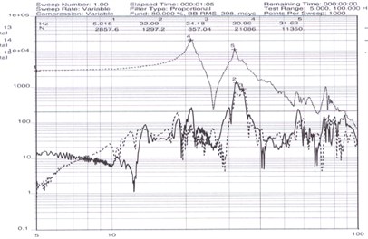
Fig. 5The summing signals for high level test (Y)
4.3. Test result analysis
The accuracy of the improved force summing method for the spacecraft force limited test at 5 Hz are shown in Table 6-7. From the data inside the table we can see that the force summing signal error is basically within 10 % compared the computational value to the actual measurement value coming out of the force transducers except for the moment of the direction during the high level test. This force summing method basically meets the accuracy requirements of the force limited test. It can be concluded that employing the improved force summing method, the problem of how to obtain the key summing forces and moments for the complicated spacecraft force limited system with eight force transducers has been resolved.
Table 6The accuracy of the improved force summing method for the low level test
Theory computation | 2713.6 | 2713.6 | 4341.8 | 2713.6 | 4341.8 |
Actual measuring | 2857.6 | 2944.4 | 4764.3 | 2924.2 | 4634.5 |
Error | 5.3 % | 8.5 % | 9.7 % | 7.8 % | 6.7 % |
Table 7The accuracy of the improved force summing method for the high level test
Theory computation | 8466.5 | 12645.5 | 20232.8 | 12645.5 | 20232.8 |
Actual measuring | 9000 | 13804.0 | 22542.0 | 13836.0 | 22233.0 |
Error | 6.3 % | 9.2 % | 11.4 % | 9.4 % | 9.8 % |
5. Conclusions
This paper discusses an improved force summing method for the spacecraft force limited vibration test system with eight force transducers. The key point for this method is to change the combination way of the charges coming out of the eight force sensors while the formulas inside the signal conditioner have been used skillfully. From the test data, it can be concluded that this method is a very powerful tool for providing the critical force and moment data used to characterize the dynamic behavior of the spacecraft during the force limited vibration test.
References
-
NASA-HDBK-7004B, Force Limit Vibration Testing, 2003.
-
Scharton T. D. Force Limited Vibration Testing Monograph, NASA-RP-1403, May, 1997
-
Rice C. E., Buehrle R. D. Validation of Force Limited Vibration Testing at NASA Langly Research Center. NASA/TM-2003-212404, 2003.
-
Zhang Jungang, Pang Hewei The force limited control technique in vibration test. Spacecraft Environment Engineering, Vol. 22, Issue 5, 2005, p. 253-256.
-
Yue Z., Zhang J., Feng Y., Wang J. The study of force specification in spacecraft force limited vibration testing. Proceedings of ISMA2014, Leuven, Belgium, 2014, p. 695-704.
-
Yue Zhiyong, Zhang Jungang Feng Yaoqi The study of force limits specification in spacecraft force limited vibration test. Spacecraft Environment Engineering, Vol. 27, Issue 3, 2010, p. 332-335.
About this article

