Abstract
This paper describes the method of determining reasonable test levels for product of spacecraft with big size, low mass and high test levels when the force of the shaker facilities is limited. The major step is to compute the test envelope from both Newton’s law and Ampere’s force aspects, the minimum of which is defined as the final safety control envelope for flight spacecraft hardware. By using this method, the shaker facilities can provide maximum force for spacecraft experiencing effective assessment and the interruptions can be avoid during the process of test operation.
1. Introduction
As rapidly growing development of space technology, different kinds of spacecraft have been manufactured. The characteristics of these spacecraft are that the size is large, the structure is complicated and the number of its sub-systems is increasing. To ensure the successful launch of spacecraft and its stable function in the orbit, the dynamic environmental test needs to be carried out not only on the components, subsystems of the spacecraft but also the whole spacecraft itself [1-9].
While for some large components of spacecraft with big size, high test levels, some of shaker facilities can’t meet its test requirements unless by lowering the test levels. The product will be experiencing under test when the test levels decrease too much while experiencing shock risks when the test levels lowers too little that the shaker facility cannot provide. So this paper seeks to find a reasonable solution to determine the control envelope for spacecraft based on the force of shaker. By employing this solution, the shaker test facilities can provide maximum force for spacecraft experiencing effective assessment and the interruptions can be avoid during the process of test operation.
2. The design of current monitoring device
The current index of power amplifier’s is of great importance for the evaluation of shaker’s force during the vibration test of the spacecraft. The top priority of the determination method of sine control envelope of spacecraft based on the force of a shaker is to obtain the current value of the armature during its operation.
So, the first step is to design a set of current monitoring device converting the current signal of the armature into the voltage signal that can be measured by the vibration controllers.
2.1. Current transducer installation
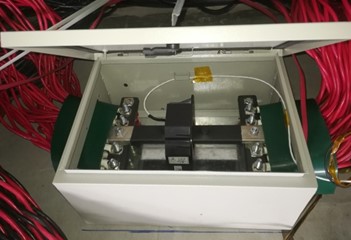
The current transducer should be placed on the positive or negative cables of the shakers, close to the power amplifier or armature. The maximum measured value of current transducer should be one and half times the maximum current value the power amplifiers can provide. So for some special power amplifiers, it is possible to cut the cables firstly and then using a copper bar to connect them again. The copper bar should be placed in the middle of the current transducer for the purpose of accurate measurements [10]. Also, special attention should be paid to the cross section areas of the copper bar. Its cross section areas should be larger than the total cross section areas of the power amplifier’s cables. The current sensor must be well protected using a special box with good grounding. Fig.1 shows the current transducer of large shaker facilities.
Fig. 1The current transducer for large shaker facility
2.2. Current monitoring converter
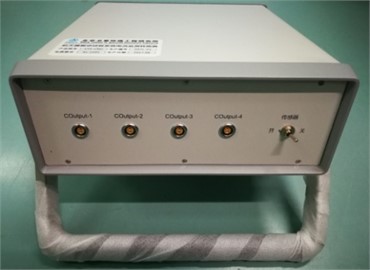
The output signal of current transducer is generally very small current signal. So a appropriate resistance is needed to translate the small current signal into voltage signal that can be measured by the control system or acquisition system. The supply voltage for the current transducer is ±24 V, the maximum range is 0-2000 A and the output current range is 0-400 mA. The maximum voltage of the current monitoring converter is set to ±10 V. According to the output range of the current transducer and the current monitoring converter, then the resistance value can be computed. It is around 25 Ω. It is usual to design up to four channels for backup. The design principle diagram of current monitoring converter is shown in Fig. 2. The current monitoring converter is shown in Fig. 3.
Fig. 2The design diagram for current monitoring converter
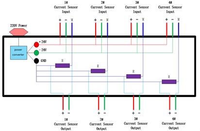
Fig. 3The current monitoring converter
3. The introduction of control envelope determination
For the large vibration test facilities, the total mass of moving parts mainly consist of the mass of armature, the expander or slip table, the connecting bolts, etc.:
The manufacturer of shaker facilities should provide the information of its maximum force capabilities. This mainly include the acceleration magnitude-frequency profile that shaker can reach. After the shaker was installed on site, the test operator would use the maximum acceleration profile to test the shaker facilities. Multiple points average control strategy is usually employed during the test. The current magnitude-frequency profile can be obtained using the controller according to the signals from the current monitoring converter. The filter mode is preferably recommended.
3.1. Employing Newton’s law to determine the control envelope
We suppose the mass of the spacecraft is , the maximum acceleration level of bare shaker is . Before conducting the vibration test of the spacecraft, the sine control envelope can be determined according to the force equivalent principle by the following equation:
From above equation, we can see that the control envelope is proportional to the maximum profile of bare shaker given by manufacturer.
3.2. Employing Ampere’s force to determine the control envelope
We also suppose the mass of the spacecraft is . The low level sine test should be carried out for the spacecraft. The test level is flat and usually at the range of 0.1 g to 0.5 g. The current magnitude-frequency profile of low level test can be obtained. Then by using the maximum current profile of bare shaker, the current profile of low level test and the acceleration value of low level test, then the sine control envelope can be determined according to the Ampere’s force equivalent principle by the following equation:
3.3. Final control envelope determination
By employing the Newton’s law and the Ampere’s force method, two control envelopes are computed. The minimum envelope of that two control envelope is defined as the final safety control envelope while the maximum envelope of that two control envelope is defined as the final usable control envelope for the spacecraft sine vibration.
For the flight spacecraft, the final safety control envelope is recommended. While for the qualification spacecraft, the final usable control envelope can be employed.
4. Engineering application case
4.1. Test introduction
The maximum force of shaker test facility is 350 kN. The armature of the shaker’s is directly connected with the expander for the vertical test while for the horizontal test the armature is indirectly connected with the slip table through a bar. The mass of the armature is 350 kg, the expander is 1300 kg, so the total mass of the bare shaker for the vertical test is 1650 kg. The mass of the bar is 150 kg, the hydrostatic bearing is 225 kg, and the slip table is 940 kg, so the total mass of the bare shaker for the horizontal test is 1665 kg.
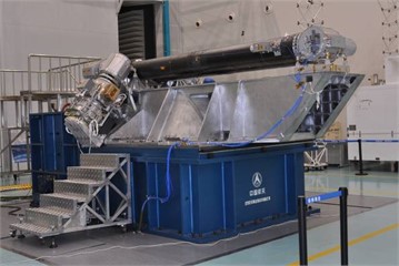
The unit under test is one component of space station. Its mass is around 800 kg. The test product on the shaker’s slip table is shown in Fig. 4.
Fig. 4The component of spacecraft placed on the slip table
4.2. Test process and analysis
The vibration test of product is usually performed by the single-axis shaker facilities. Electro-dynamic shakers have been used for vibration testing of spacecraft hardware by applying uniaxial excitation. Due to three direction tests is carried out through sequentially-applied uniaxial testing, the sine control envelope should be determined at each direction. This paper mainly introduces the detailed test process of product for the horizontal direction.
The maximum reference profile of the bare shaker is given by Fig. 5. By using the reference and four-point average control strategy, a sine vibration test is carried out and the current profile of bare shaker is obtained shown by Fig. 6. From the curve we can see that the maximum current value reach nearly 2000 A. The frequency range of low level test of the UUT is from 5-100 Hz. The test level is 0.2 g. The sweep rate is 4 Oct/min. Fig.7 shows the low level test profile for the product. After the low level test completed, the current profile is obtained shown by Fig. 8.
By employing the method of Newton’s law , the first control envelope is determined according to the maximum reference profile of bare shaker, the mass of horizontal shaker and the mass of spacecraft product. By using the maximum current profile of bare shaker, the current profile of low level test and the acceleration value of low level test, then the second control envelope can be determined according to the Ampere’s force equivalent principle. The two control envelopes are shown by Fig. 9.
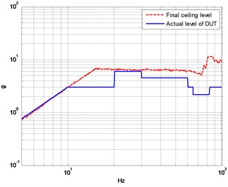
Due to UUT is the flight product, so the minimum envelope of that two control envelope is used as the final safety control envelope shown by the red line in Fig. 10. The designer of the test product determined the actual reference level that the product would experience. From Fig. 10, it can be seen that the actual level of UUT is below the final safety control envelope at large parts of the frequency range.
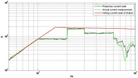
According to the reference and current curve of low level test, the high level test reference, then the current curve of high level test can be projected. Fig. 11 shows the current of projected envelope, the actual measurement and the maximum current profile of bare shaker. From the curve, we can see that the actual measurement is very close to the projections while both of them are below the maximum current profile of bare shaker.
Fig. 5The max reference profile of the bare shaker
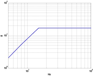
Fig. 6The current magnitude profile of bare shaker
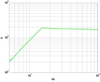
Fig. 7The low level test profile for the product
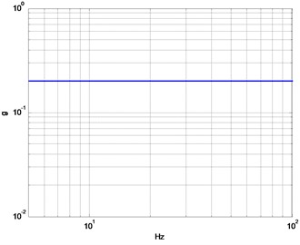
Fig. 8The current magnitude profile of the product
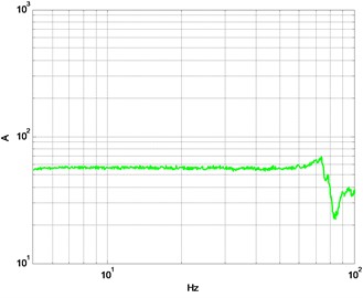
Fig. 9The two control envelopes
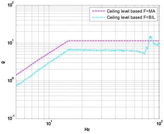
Fig. 10The final safety control envelope and the actual reference level for the product
5. Conclusions
This paper talks about how to determine the method of spacecraft sine control envelope based on the force of shaker from two aspects: Newton’s law and Ampere’s force. The minimum envelope of that two control envelope is defined as the final safety control envelope which is can be used for flight spacecraft. This method can resolve the unreasonable test problems for spacecraft with big size, low mass and high test levels and the interruptions of the facility can be avoid during the test operation. It has been proved to be a very effective technique in spacecraft environmental vibration test and good results have been achieved.
Fig. 11The projection, the actual measurement and the max envelope at high test level
References
-
A. Russell, M. Underwood, and T. Keller, “Controlling 6-DOF systems with multiple exciters,” Sound and Vibration, Vol. 47, No. 10, pp. 6–11, 2013.
-
M. A. Underwood, “Multi-exciter testing applications: theory and practice,” Proceedings – Institute of Environmental Sciences and Technology, 2002.
-
H. P. Qih and Y. Q. Feng, “A new method for dual-shaker sine vibration control,” Spacecraft Environment Engineering, Vol. 23, No. 6, pp. 355–358, 2006.
-
H. Qiu et al., “Investigation of in-phase vibration control technology for large multi-shaker test facility,” Vibroengineering Procedia, Vol. 42, pp. 33–38, May 2022, https://doi.org/10.21595/vp.2022.22486
-
M. H. Liu et al., “Application of FEA in structure design of large vibration test bed,” Spacecraft Environment Engineering, Vol. 33, No. 3, pp. 257–261, 2016.
-
Q. Zhang et al., “An interface force monitoring and vibration control method based on the armature of shaking table and its engineering application,” Spacecraft Environment Engineering, Vol. 36, No. 1, pp. 69–75, 2019.
-
Z. J. Li, X. R. Ma, and Z. Y. Han, “Research on the estimation of force specifications for force-limited vibration testing,” Advances in Mechanics, Vol. 42, No. 4, pp. 454–463, 2012.
-
Z. W. Chen et al., “Application of force limited control in vibration test,” Journal of Vibration and Shock, Vol. 32, No. 6, pp. 105–108, 2013.
-
T. D. Scharton, “Force Limited Vibration Testing Monograph,” Pasadena: Jet Propulsion Laboratory, California Institute of Technology, Jul. 1997.
-
H. Qiu et al., “Health monitoring device design and application for large synchronously excited multi-shaker vibration test facility,” Vibroengineering Procedia, Vol. 20, pp. 11–16, Oct. 2018, https://doi.org/10.21595/vp.2018.20112
About this article

The authors have not disclosed any funding.
The datasets generated during and/or analyzed during the current study are available from the corresponding author on reasonable request.
The authors declare that they have no conflict of interest.
