Abstract
There are different kinds of equipments distributed in different locations for a large complicated multi-shaker vibration test facility, so it is challenging to monitor the real state of test facility thoroughly during its operation. Long-term operation of this test facility will lead to the degradation of reliability and malfunction, and sometimes the emergency stop of the whole test system that threatens the safety of the spacecraft seriously. This paper presents in detail the design and application of a set of health monitoring device for a large multi-shaker vibration test facility which is capable of monitoring the operation state in real time and predicting the potential malfunction of the whole test facility to ensure the reliability of this large test system and safety of the spacecraft during its environmental vibration test.
1. Introduction
The spacecraft experiences complicated vibration environments during it launch, flight and re-entry stage. These vibration environments would affect the structure of the spacecraft or the equipment through the dynamic transfer process, and sometimes result in the damage of the structure, the degradation of the equipment function and malfunction.
Based on the influence of these vibration environments to the structure or the equipment of spacecraft, it is necessary to reproduce those environments experienced by the spacecraft to ensure the successful launch and normal function of the spacecraft during its life period.
Most of the major space centers worldwide including ESTEC, NASA, etc. have constructed large vibration test facilities in recent years to meet the needs of large spacecrafts’ environmental vibration test [1, 2]. There are different kinds of equipment’s distributed in different locations for a large complicated vibration test facility, so it is a challenging issue to monitor the real state of test facility fully during its operation. So, it is necessary to build a set of health monitoring device for this kind of test facility capable of monitoring the operation state in real time and predicting the potential malfunction to ensure the reliability of this large test system and safety of the spacecraft during its environmental vibration test.
2. The composition of large multi-shaker vibration test facility
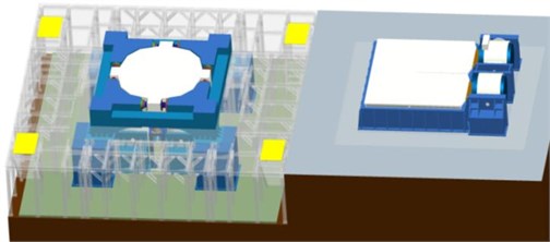
The large multi-shaker synchronously-excited vibration test facility made by BISEE in China consists of 1400 kN vertical vibration system (VVS-1400) and 700 kN horizontal vibration system (HVS-700). This test facility mainly includes vibration controller, shaker, vertical head expander, slip table, power amplifier, external water-circulation cooling unit, etc. The three direction vibration tests of large spacecraft have been performed by this large test facility.
VVS-1400 comprises a cluster of four shakers as the dynamic source topped with a large magnesium head expander guided by sixteen hydrostatic bearings while HVS-700 adopts a cluster of two shakers as the dynamic source moving a big slip table consisting of three small magnesium tables back and forth [3]. Each shaker’s thrust force is 350 kN.
Fig. 1Large multi-shaker vibration test facility
3. Health monitoring device design
3.1. The design and configuration of sensors and acquisition module
The monitoring parameters and locations for this large test facility are listed as follows: (1) acquire the water temperature and height inside the tank for shaker’s armature and magnetic field, the water pressure of the pump, the water flux going back to the tank. (2) acquire the lubricating oil temperature and height inside the tank for guiding bearings of the shaker itself, the oil pressure of the pump, the oil flux going back to the tank. (3) acquire the lubricating oil temperature and height inside the tank for guiding bearings of vertical head expander, the oil pressure of the pump, the oil flux going back to the tank, the gas pressure for the expander’s airbags. (4) acquire the temperature and height of lubricating oil inside the tank for bearings of the slip table, the oil pressure of the pump, the oil flux going back to the tank. (5) acquire the total electrical current of the power amplifier. (6) acquire the water temperature, pressure and flux of the external water-circulation cooling system. The installations of all different kinds of sensors are shown by Fig. 2 to Fig. 5.
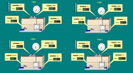
Fig. 2Sensors for shakers
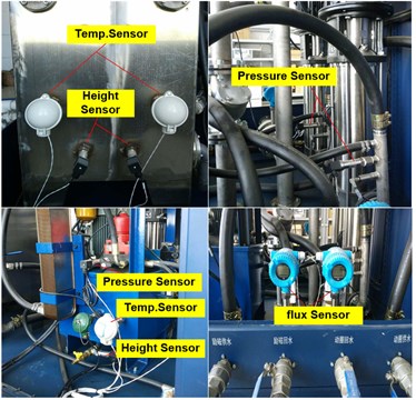
Fig. 3Sensors for vertical head expander
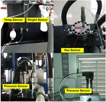
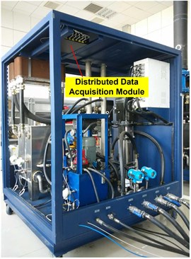
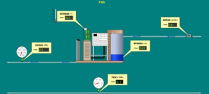
The health monitoring device adopts eight acquisition modules in total. Each shaker was equipped with a general acquisition module respectively. There are two exclusive acquisition modules. One is collecting parameters for the vertical head expander especially while another one is collection parameters for the slip table. Distributed acquisition module has been employed for the health monitoring device because of sparse distribution of the sub-systems. The distributed acquisition module collects the parameters of its corresponding sub-system and then sends the data to the host of the health monitoring device. The sampling rate of the acquisition module is 2 kHz. Fig. 6 shows the location of the distributed acquisition module which uses the network server to communicate with the host.
Fig. 4Sensors for horizontal slip table
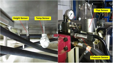
Fig. 5Sensors for amplifier and cooling system
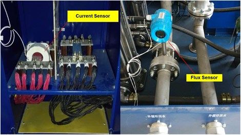
Fig. 6The installation location of distributed data acquisition module
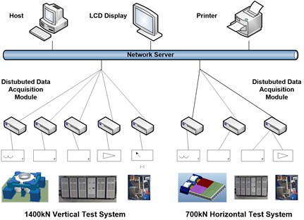
This large multi-shaker vibration test facility adopts the idea of distributed module design showed by Fig. 7 that is very convenient for future expansion and maintenance.
Fig. 7The design layout of the health monitoring device
3.2. Software design
The software of the health monitoring device shall possess the function of parameter configuration, data acquiring, processing, displaying, saving, replaying and alarming [4, 5].
The parameter configuration includes the set of user’s authorization. The module for acquisition channel is responsible for the input of the sensor’s sensitivity, gain, filtering range, power supply, etc. The module for parameters defining is responsible for setting the sampling rate and channel self-checking.
The data processing module is capable of collecting data of different kinds of sensors, analyzing, processing and computing the value that the device is interested in. For the slowly changing parameters such as the temperature, height, pressure and flux, the data processing module only finds the maximum value during an acquisition period. While for the swiftly changing parameter such as the electrical current of the power amplifier, the data processing module calculates not only the frequency based on the COLA (Constant Output Level Adaptor) signal from the vibration controller, but also the peak value of the current frequency within an interested acquisition range.
The data displaying module shows the resultant data after processing through the user interface. The data saving, and replaying module saves all the data into the database waiting for replaying. The data alarming module shows the alarming information on the screen when the data is beyond the tolerance band.
4. The application of health monitoring system
4.1. Monitoring sensors’ information
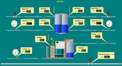
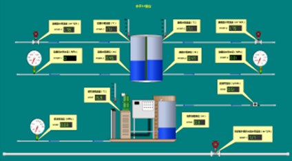
There are five different kinds of up to 105 sensors have been installed on this large multi-shaker vibration test facility. Table 1 shows the detailed information of the data information during its operation. Fig. 8 and Fig. 9 shows the user interface of health monitoring device for VVS-1400 and HVS-700 respectively.
4.2. Classical cases of malfunctions detection
This health monitoring device plays an important role in detecting the malfunction of the large test facility in time during its past operation. Now two classical cases have been given as following:
(1) During the preparation for a spacecraft vertical vibration test, the test operator found that the water temperature of armature (22 ℃) for No. 3 shaker was a bit higher than other three shakers (20.5 ℃). So, the pipe of the No. 3 shaker had been checked thoroughly and finally we found that there was something stuck in the tank which decreased the heat exchange efficiency with the external cooling system. The temperature returned to normal value after the removal of a small piece of stuff.
(2) During the low level sinusoidal sweeping test of the head expander, the test operator found that the phase of the No. 3 shaker’s electric current time history was out of phase with other three shakers. Then the expander had been removed and No.3 shaker had been checked individually. The examination showed that there was disconnection between two cables inside the shaker. The test facility returned to normal operation after carefully repairing.
Fig. 8User interface of health monitoring software for VVS-1400
a)
b)
Fig. 9User interface of health monitoring software for HVS-700
a)
b)
Table 1The normal value and alarming band for all different kinds of sensors
No. | Subsystem | Equipment | Medium | Monitoring physical value | Normal value | Tolerance band |
1 | Shaker | Armature | Water | Temp. | 20 ℃ | [–10, +10] ℃ |
2 | Height | 0.45 m | [–0.05, +0.05] m | |||
3 | Press. | 1.0 MPa | [–0.2, +0.2] MPa | |||
4 | Flux | 4.5 m3/h | [–0.5, +0.5] m3/h | |||
5 | Magnetic field | Water | Temp. | 20 ℃ | [–10, +10] ℃ | |
6 | Height | 0.45 m | [–0.05, +0.05]m | |||
7 | Press. | 1.0 MPa | [–0.2, +0.2] MPa | |||
8 | Flux | 11 m3/h | [–0.5, +0.5] m3/h | |||
9 | Pump | Oil | Temp. | 23 ℃ | [–10, +10] ℃ | |
10 | Height | 0.3 m | [–0.05, +0.05]m | |||
11 | Press. | 18 MPa | [–0.5, +0.5] MPa | |||
12 | Flux | 4.3 L/min | [–0.5, +0.5] L/min | |||
13 | Head expander | Pump | Oil | Temp. | 22.5 ℃ | [–10, +10] ℃ |
14 | Height | 0.25 m | [–0.05, +0.05] m | |||
15 | Press. | 2930 psi | [–50, +50] psi | |||
16 | Flux | 0.5 L/min | [–0.1, +0.1] L/min | |||
17 | Airbag | Gas | Press. | 0.25 MPa | [–0.05, +0.05] MPa | |
18 | Slip table | Pump | Oil | Temp. | 28 ℃ | [–10, +10] ℃ |
19 | Height | 0.3 m | [–0.05, +0.05] m | |||
20 | Press. | 17.5 MPa | [–0.5, +0.5] MPa | |||
21 | Flux | 14 L/min | [–0.5, +0.5] L/min | |||
22 | Power amplifier | / | Current | Total current | / | [0, 1200] A (Absolute) |
23 | External cooling system | Cooling unit | Water | Flux | 30 m3/h | [–2, +2] m3/h |
5. Conclusions
This paper discusses a set of health monitoring device for a large multi-shaker vibration test facility with a high monitoring precision, a wild monitoring range and a friendly user interface. This device is capable of monitoring the operation state of the whole test facility in real time and predicting the potential malfunction. It has been currently used in spacecraft environmental vibration test successfully. From the cases of malfunction detection, it can be concluded that this device is playing an important role not only in enhancing the reliability of this large test facility, but also protecting the safety of the spacecraft during its vibration test.
References
-
Popovitch Alexandre Multishaker upgrade at ESTEC, ESA. Proceedings of the 22nd Aerospace Testing Seminar, The Aerospace Corporation, 2005.
-
Touzelet Pierre, Popovitch Alexandre, Piret Gaetan The ESTEC new quad head expander. Proceedings 6th International Symposium on Environmental Testing for Space Programmes, Noordwijk, The Netherlands, 2007.
-
Liu Minghui, Wang Jian, Gao Haiyang Application of FEA in structure design of large vibration test bed. Spacecraft Environment Engineering, Vol. 33, Issue 3, 2016, p. 257-261.
-
Yan Zhigang, Yue Qing, Shi Zhou Design of Structural health monitoring system for Hutong Changjiang river bridge. Bridge Construction, Vol. 47, Issue 4, 2017, p. 7-12.
-
Du Yan Liang, Su Mu Biao, Liu Yu Hong Study on the long-term health monitoring and safety evaluation system for the Wuhan Yangtze river bridge. Journal of the China Railway Society, Vol. 27, Issue 4, 2015, p. 101-110.
About this article

