Abstract
Aiming at the problems that the three-direction uniaxial sequential vibration test cannot effectively simulate the real launch environment of the satellite, and the high cost of the multi-axis shaker and the limitation of engineering application, the multi-axis vibration test scheme based on vector-fixture is proposed. Taking the vibration magnitude of uniaxial vibration test on the satellite mounting surface as equivalent reference, the appropriate vector direction is determined to carry out vector-fixture design. By analyzing the multi-axial vibration test data of the real structure of a satellite, it can be seen that: The “satellite-fixture” mounting surface can reach the set vibration magnitude at low frequencies, and undertest occurs at high frequency due to structural resonance and other factors; By optimizing the control strategy, the degree of over-test and under-test in the three directions can be balanced. According to the mission characteristics and development cycle of micro-nano satellites, this paper provides an efficient vibration test scheme.
1. Introduction
Satellites have to withstand harsh vibration environments during transportation, launch and flight stages. The real dynamic environment often occurs simultaneously in multi-axis, and the vibration magnitudes in each direction are different. Basically, the flight direction of the satellites has the largest vibration magnitude, and the other two orthogonal directions are much smaller [1]. Due to practical constraints such as the complexity and high cost of the multi-axis shaker and the immature test standard of multi-axis vibration [2], the satellites vibration test usually uses a uniaxial shaker to conduct uniaxial vibration tests in three directions in sequence to simulate the multi-axis vibration environment actually experienced [3]. Liu et al. conducted uniaxial and multiaxial vibration tests on typical specimens, and the results show that multi-axis simultaneous vibration has obvious multiaxial effects compared with uniaxial sequential vibration fatigue tests, which can lead to structural fatigue failure, electrical connector loosening, etc. [4].
The multi-axis vibration realizes simultaneous vibration in three directions through one installation and loading, while reducing the number of disassembly and hoisting, and greatly improving the efficiency of the test [1]. In recent years, with the development of low-cost, fast-delivery micro-nano satellite development technology, it is urgent to use technologies such as multi-axis vibration to quickly complete the test tasks. Multi-axis vibration research is mainly based on multi-axis shaker to carry out the control technology research of MIMO system. However, the actual engineering implementation is difficult, the equipment cost is high, and many shortcomings are exposed in use. For example, the upper frequency is determined by the transmission characteristics of the connecting ball joint, the coordinated control of multiple shakers is difficult when the structure is complex. As a result, multi-axis testing is only suitable for small, simple stand-alone products for vibration testing [5]. In this paper, the multi-axis vibration technology based on vector-fixture is studied. Through the application of the traditional uniaxial shaker and the vector-fixture, the simultaneous vibration of the three orthogonal directions of , , and can be realized, and the real vibration environment can be simulated more efficiently and realistically, which create new research ideas and approaches for product reliability assessment, and lay a certain research foundation for the practical application of multi-axis vibration.
2. Multi-axis excitation response analysis
The multi-axis vibration test system based on vector-fixture can be described as a single-input, single-output system shown in Fig. 1. The driving signal of the system is decomposed by the vector fixture () to produce the qualified response output signal at control points.
Fig. 1Multi-axis vibration test system based on Vector-fixture
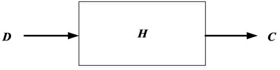
The transfer function of the system is determined by the frequency response characteristics of the vector fixture, which is the key link of the system. Assuming that the multi-axis vibration test system based on vector-fixture is a linear time-invariant system, the input and output signals of the system can be expressed in the frequency domain as:
where, is the system response vector; is the system transfer function matrix; is the driving signal vector. The direction of vector is parallel to the satellite coordinate system, the direction of vector is parallel to the motion direction of the shaker, and realizes the transmission of vibration magnitude and the direction conversion of the coordinate system. Then:
Ideally, in is a fixed value that does not vary with frequency, given by the vector-fixture design characteristics. In practical engineering applications, affected by the design results of the fixture, it is difficult to ensure the stable transmission of the frequency response in the full frequency band, which leads to the uneven response caused by resonance and anti-resonance in different control points and different frequency.
3. Vector fixture design
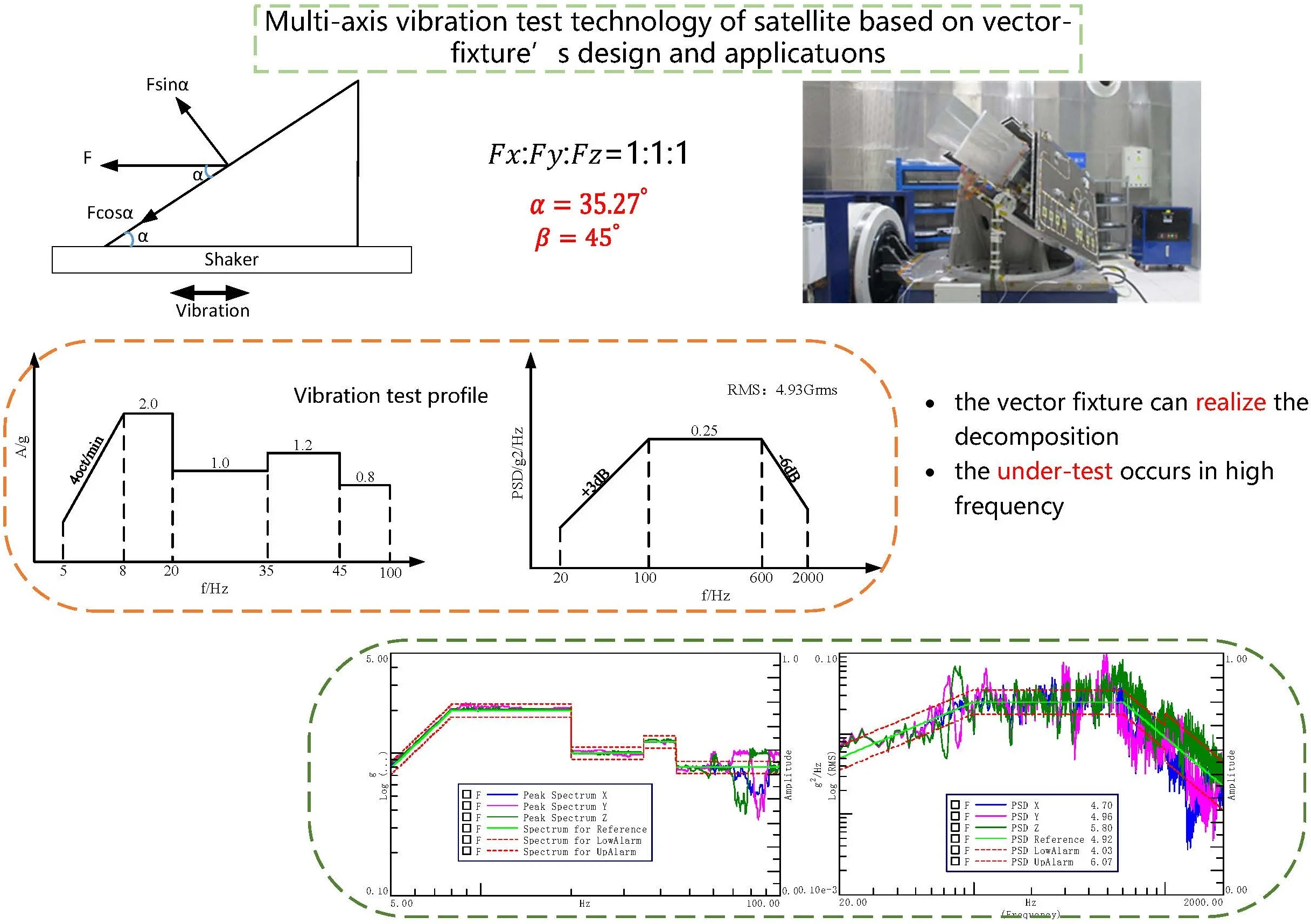
The vibration fixture is mainly used to realize the connection between the satellite and the shaker. Compared with the traditional fixture, the vector-fixture can further realize the decomposition of the acceleration magnitude according to the design proportion and the conversion of the driving direction.
When the shaker vibration load is and the direction is perpendicular to the base of the vector fixture, as shown in Fig. 2. The angle between the satellite mounting surface and the fixture base is , the angle of mounting is , and the centroid of the satellite is located in the center of the fixture. Then the load of the satellite in three directions is: , , .
In order to ensure that the satellite can complete the assessment in , and directions according to the specified magnitude through a single load, the Angle and design should be carried out in the design of vector fixture. Simply, it is assumed that the conditions in , and directions of the satellite are identical, i.e. , then:
From, , get .
Then, 45°.
From, and 45°, get .
Then, 54.73°.
Fig. 2Vector fixture angle design diagram (vertical)
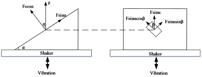
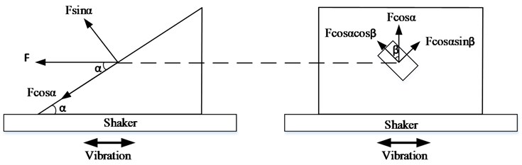
Similarly, when the direction is parallel to the base of the vector fixture, as shown in Fig. 3. It is assumed that the conditions in , and directions of the satellite are identical, i.e. , then:
From, , get .
Then, 45°.
From, and 45°, get .
Then, 35.27°.
Fig. 3Vector fixture angle design diagram (horizontal)
4. Multi-axis vibration
4.1. Test conditions and vector-fixture
In order to verify the acceleration decomposition of the vector-fixture on the satellite mounting surface, sinusoidal and random vibration were carried out on a satellite structure according to the multi-axial vibration based on the vector-fixture. To comparative analysis, the load spectrum corresponding to the , and directions of the traditional uniaxial vibration of the satellite is used as the load spectrum of the multi-axial vibration and vector-fixture design. Considering the convenience of operation, the horizontal excitation is used to design the vector-fixture (as shown in Fig. 3).
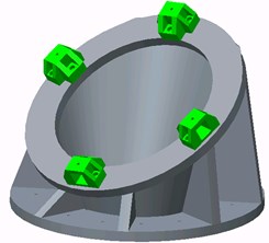
The load spectrum is shown in Fig. 4(a)-(b), and the 3D diagram of the fixture is shown in Fig. 5.
Fig. 4Multi-axis vibration test profile
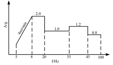
a) Sine
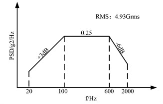
b) Random
Fig. 5Schematic diagram of Vector-fixture
4.2. Decomposition results of the Vector-fixture
The satellite is fixed on the horizontal slide of the shaker by the Vector-fixture, as shown in Fig. 6. Four triaxial acceleration sensors, which are parallel to the satellite coordinate system, are pared on the “satellite-fixture” mounting surface for vibration closed-loop control, while collecting the decomposed acceleration values of the vector-fixture on the mounting surface.
The sinusoidal vibration test is carried out according to the conditions shown in Fig. 4(a), and the control strategy adopts two control modes: “X&Y&Z direction four-point maximum control” and “X-direction four-point maximum control +Y&Z direction quasi-identification magnitude response limit”. The vibration magnitude decomposition results on the satellite installation surface are shown in Fig. 7(a)-(b). The peak spectrum of , and shown in the figure are the result after the data of the four control points are processed according to the maximum control algorithm.
Fig. 6Multi-axis vibration satellite installation diagram
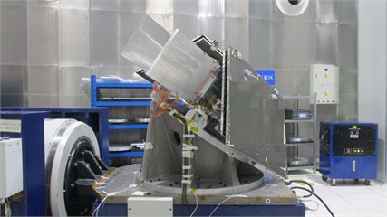
Fig. 7Sinusoidal vibration
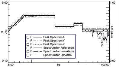
a) X&Y&Z maximum control
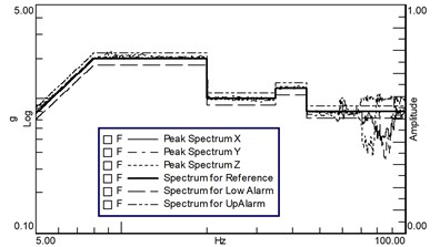
b) X maximum control +Y&Z response limit
Affected by the modal characteristics of the fixture and the “satellite-fixture” coupling characteristics, the acceleration decomposition of the fixture failed to be smoothly and uniformly realized in the sinusoidal vibration test. The required test conditions and tolerance limits were not exceeded in the whole frequency band, but undertest occurred at high frequencies above 70 Hz. By changing the control strategy, undertrials can be reduced, but not eliminated completely.
Fig. 8Random vibration
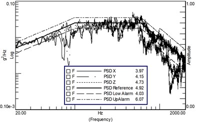
a) X&Y&Z maximum control
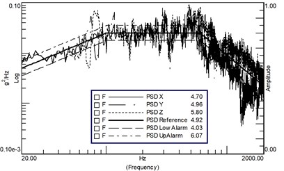
b) X maximum control +Y&Z response limit
The random vibration was carried out according to the conditions shown in Fig. 4(b), and the control strategy was the same as that of sinusoidal vibration. Firstly, the mode of “X&Y&Z direction four-point maximum control” was adopted. The vibration decomposition results of the satellite mounting surface are shown in Fig. 8(a). Except for a few frequency points, the spectral density is basically within the upper limit of the test tolerance, but the spectral density of the high frequency band is seriously undertested, and the RMS value of the direction and direction is undertested. Just like the sinusoidal vibration, the PSD of , and shown in the figure are the result after the data of the four control points are processed according to the maximum control algorithm.
By optimizing the control strategy and adopting the method of “four-point maximum control +Y&Z direction quasi-identification magnitude response limit”, the degree of over-test and under-test of the spectral density in the three directions is balanced, the total RMS value in the Z-direction exceeds the acceptance level but does not exceed the identification level, and the total RMS value in the and directions is within the tolerance limit of the test conditions, as shown in Fig. 8(b) (The 90 Hz peak is the satellite first-order mode, which can be limited within the tolerance by the under-concave control strategy).
5. Conclusions
In order to analyze the effect of multi-axis vibration test method based on vector fixture, this paper takes a real satellite structure as an example to carry out three-axis vibration test based on vector-fixture. The measured data show that the vector fixture can realize the decomposition of acceleration in three axial directions, and the decomposition results in low frequency meet the design requirements, while the under-test occurs in high frequency due to the coupling effect of “satellite-fixture” modal characteristics. In the future, the fixture design scheme will continue to be optimized to reduce the coupling influence of “satellite-fixture” and achieve uniform decomposition in a wider frequency range.
The test conditions used in this paper are calculated from the traditional uniaxial vibration, and the traditional uniaxial test conditions are obtained by weighting and envelope processing of the measured data in the actual environmental conditions, which are larger than the actual environmental conditions. In the subsequent satellite development, the satellite developer and the launcher will be gradually coordinated to optimize the vibration test conditions, so as to simulate the actual environmental conditions more realistically and efficiently. In the current large-scale satellite development, the multi-axis vibration test method based on vector-fixture can achieve the goal of rapid vibration assessment and improve the overall development efficiency of satellites.
References
-
L. Zhang, “Enlightenment from the Verification of the Ground Environment Test of the Orion Spacecraft,” Noise and Vibration control, Vol. 38, pp. 584–590, 2018.
-
J. Bai, “Tailoring method for triaxial vibration load spectrum preserving pattern,” Journal of Xidian University, Vol. 46, pp. 88–94, 2019.
-
H. Wang, “Load clipping method based on the maximum stress equivalence between triaxial and uniaxial random vibration,” Journal of Vibration and Shock, Vol. 36, No. 6, pp. 86–90, 2017.
-
S. Liu, “Loosening mechanism and stress-resistance mapping relationship of electrical connector under triaxial random vibration,” Journal of Vibration and Shock, Vol. 40, No. 11, pp. 190–195, 2021.
-
M. Wang, “Multi-dimensional Vibration testing practice,” Equipment Environmental Engineering, Vol. 2, No. 3, pp. 22–25, 2005.
About this article

The authors have not disclosed any funding.
The datasets generated during and/or analyzed during the current study are available from the corresponding author on reasonable request.
The authors declare that they have no conflict of interest.
