Abstract
According to the pictures of a sub-meter resolution optical satellite which were acquired on orbit, there is a phenomenon of jitter in the process of taking pictures. As the main attitude control component of the satellite, the flywheel will produce the disturbance in its normal work, which has great influence on the high resolution optical satellite. This paper has respectively researched the flywheel components’ disturbance mechanism from four parts, including uneven rotator, rotator friction, bearing disturbance, foundation loose, and builds the mathematical model of disturbance to analyze the characteristics of disturbance. We have simulated and tested the flywheel components’ disturbance. The disturbance force of flywheel components is 2 N magnitude and the torque of disturbance is 1.5 N·m magnitude in time domain. The flywheel's infrastructure should be more inflexible especially around 90-100 Hz. For this target high resolution optical satellite, there should be effective damping measures around 48.6 Hz, 190.4 Hz and 285.4 Hz to decrease the flywheel disturbance to guarantee the high precision of the satellite. The result would offer guidance for system optimization design and vibration isolation compensation of the later type of improved satellite or other same type of satellites.
1. Introduction
With the rapid development of space remote sensing technology, the high-quality and high-resolution imaging of spacecraft systems have been paid much attention by countries around the world. The development of space optical remote sensor has entered the era of sub-meter development. The United States launched the commercial remote sensing satellites GeoEye-1, which ground resolution is 0.41 meters in 2008. India launched the Remote Sensing Satellite-2 with a ground resolution of 0.8 meters in 2006. The Pleiades-1 satellite with a ground resolution of 0.5 meters had been launched in France in 2011 [1]. China launched GF-2 whose resolution is less than one meter in 2014.
The resolution of optical satellite is constantly improved, while the pointing precision of space optical camera is higher. The micro vibration which caused by the moving parts on the satellite in orbit is becoming more sensitive for space optical camera. These vibrations would not cause damage to the structure of the satellite, but it will affect the pointing accuracy and stability of high resolution satellite [2-4].
Flywheels commonly used as attitude control execution units in modern high stability and high precision spacecraft [4-6]. Due to the rotor dynamic, static unbalance, driving motor error, bearing defects and other factors, the flywheel components will produce complex harmonic disturbance and noise in its normal spinning, which makes the flywheel become one of the main disturbance sources [7-9]. The vibration isolation design for flywheel components is an effective method to achieve the requirement of the precision of spacecraft. The Chandra X-ray Observatory using a six degree of freedom vibration isolation platform for each flywheel to separate isolation, and the platform will also be applied in the JWST [5, 8]. The disturbance caused by flywheel or Control Moment Gyroscope (CMG) is measured in Ref. [5], and the main disturbance of typical micro vibration source are summarized. Ref. [10] adopts the integrated model method to get the image displacement of the optical system, and puts forward the evaluation index of dynamic optical system imaging. The disturbance of flywheel rotor has been well discussed in Ref. [13]. However, there is no systematic reports on the disturbance mechanism of the flywheel components up to now [4, 6, 9, 11, 14].
There is a phenomenon of fuzzy in pictures which acquired by a sub-meter resolution optical satellite in orbit. The research shows that the disturbance of the flywheel is one of the important factors which causes the jitter [2-4, 6, 12, 13, 14]. To reveal the vibration mechanism of the flywheel disturbance on the satellite, in this paper, we researched the flywheel disturbance characteristics, and tested flywheel components’ disturbance on the ground. We obtained the force &torque of flywheel components’ disturbance by test in its normal working. And the six-directional disturbance force / torque waterfall plots and the resonant frequency of the flywheel are obtained via signal processing. The flywheel components’ disturbance mechanism, which studied in this paper, will provide some guidance for the satellite design, particularly in the satellite control system, structure system, the micro vibration suppression performance and constraint conditions.
2. Flywheel component structure
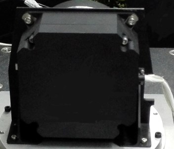
By adjusting the rotational speed of the rotor, the flywheel can exchange angular momentum with the satellite to realize the attitude control of the satellite [15]. The flywheel will provide the necessary control moment, and produce the disturbance which will affect the camera imaging. Flywheel structure shown in Fig. 1, the flywheel is composed of a rotor, a bearing, a shell and a motor. The rotor mass concentrated in the outer edge of the wheel to provide the flywheel control force. The main function of the cover is to provide a certain degree of vacuum and keep it clean, and it also maintains the momentum wheels to prevent the motor from being contaminated with space magnetic particles. The motor is a direct current motor, and the bearing is rolling bearing or magnetic bearings. The flywheel component is shown in Fig. 2. The flywheel is connected with the bracket with the help of four screws.
The flywheel component has a complex structure, which makes it has a complex vibration mechanism, various vibration, vibration coupling factors [16]. Therefore, it is necessary to analyze the disturbance mechanism of the flywheel and study the vibration characteristics. On the basis of this, the flywheel disturbance test should be studied.
Fig. 1Flywheel structure diagram
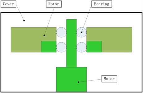
Fig. 2Flywheel component structure. Scale bar: 1:1
3. Flywheel components’ vibration characteristics
3.1. Rotor disturbance
All unbalance of the flywheel can be attributed to the mass eccentricity of the rotor [17, 18]. The model is shown in Fig. 3.
Fig. 3Flywheel rotor mass eccentric model
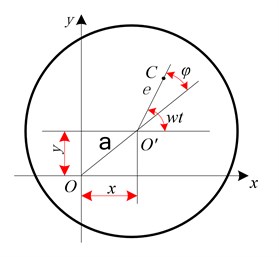
Considering damping effect, rotor eccentricity mass concentration is , the differential equation of motion of the axis indicates as Eq. (1):
where, is rotor mass, is eccentricity, is rotor angular velocity, is rotor support stiffness, – support structure damping coefficient.
The characteristic solution of Eq. (1) is:
where:
From Eq. (2), the vibration directions of and are harmonic vibration with the same amplitude, the phase difference is 90°, which shows that their axis orbit is a circular. However, the fact is that the isotropic bending stiffness of the rotor shaft is different, especially the support stiffness. The response of the rotor to the balance mass is different in the and directions, and the phase difference is not 90°, so its axis orbit is an ellipse.
According to the above analysis, the main vibration characteristics of rotor mass unbalance are as follows:
1) The steady vibration of the rotor is a forced vibration with the same frequency under the rotational speed. Vibration amplitude changes with the speed according to the vibration theory of the coaxial curve change law and reaches maximum value at the critical speed. Therefore, the outstanding performance of the flywheel rotor unbalance is a large amplitude of harmonic vibration.
2) The axis orbit of the rotor is a circle or an ellipse.
3) If the flywheel phase is stable, its speed would be stable.
4) In the first order critical speed, the amplitude of the rotor is very sensitive to the change of the rotational speed. When the rotation speed is decreased, the amplitude is decreased obviously.
Due to the actual flywheel rotor system will subject to some nonlinear factors, the vibration system is not a complete linear system. So, in the vibration spectrum of typical flywheel imbalance, it often appears smaller harmonic, in addition to the rotational speed frequency component has an absolute advantage in the total amplitude.
3.2. Flywheel rotor rub impact
During the normal operation of the flywheel, if the amplitude of the rotor was larger than the gap between the rotor and the stator, the continuous or intermittent collisions would occur. The actual impact of rotor friction process is relatively complex, so we simplified the process of rubbing without considering the friction thermal effect and plastic deformation of rotor for convenience of study. Assuming that collision is plastic deformation of stator in a short time, and the friction of rotor and stator obeys the Coulomb’s law, then the friction force and normal force is proportional at the contact surface.
As shown in Fig. 4, when the average gap between the rotor and the stator is , the normal collision impact force and tangential friction force can be expressed as:
where, is Friction coefficient, is stator radial stiffness, is rotor radial displacement.
Fig. 4Rub schematic
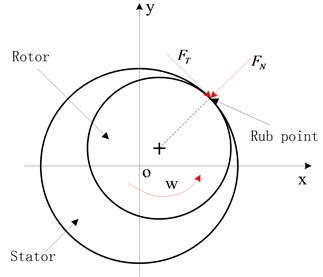
In coordinates, rubbing force is expressed as:
Due to , , Eq. (6) expressed as Eq. (7):
Rubbing Rotor System of differential equations can be expressed as Eq. (8):
Put Eq. (7) into Eq. (8), we get:
By the Eq. (9), we can known that the system is linear before the occurrence of rubbing, and the measured vibration is the same frequency component. An additional nonlinear stiffness is generated in the system after the rub occurred, which is much larger than . It also can be seen that the system has a number of different cross rigidities, which will often appear unstable motion that resulting in damage or the ultimate destruction due to the role of nonlinear damping.
Eq. (9) is a nonlinear equation. It is difficult to obtain analytical expression of the solution under normal circumstances. When the local friction occurs, the rotor has a nonlinear vibration, which is rich in the spectrum. It not only has a rotating frequency, but also have high harmonic and fractional harmonic components [19, 20].
3.3. Bearing disturbance
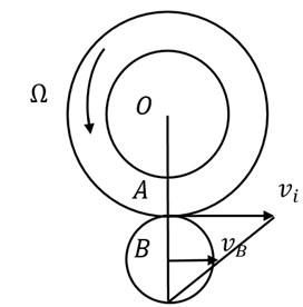
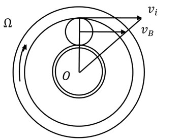
A typical rolling bearing is shown in Fig. 5, and Fig. 6 is its internal movement principle. In Fig. 6(a), the outer ring is fixed and the inner ring rotates along with the shaft. In Fig. 6(b), the inner ring is fixed and the outer ring rotates along with the shaft.
Fig. 5Typical rolling bearing
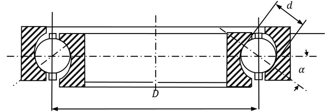
In Fig. 5 and Fig. 6, is the bearing diameter, is the diameter of the rolling, and is the contact angle. If there exist defects or damage in the rolling surface, when the rolling roll in the surface, it would produce an alternative excitation force. The exciting force is shown as a variety of harmonics of the flywheel speed. That is:
where, is the th harmonic number (not necessarily an integer), is the total number of harmonics.
The relationship between the number of harmonic wave and the structural parameters of the bearings is shown in Table 1.
Fig. 6Bearing internal components
a)
b)
Table 1The relationship between the harmonic wave number and the structural parameters
Structure state | No axial force | Axial force |
Outer ring fixed and the inner ring rotating along with the shaft | ||
Inner ring fixed and the outer ring rotating along with the shaft | ||
Defects in the outer ring | ||
Defects in the inner ring | ||
is the number of rolling elements, is the inner ring raceway diameter, is the outer ring raceway diameter, and is the raceway diameter. | ||
3.4. Flywheel component foundation loose
When the flywheel is mounted on the satellite structure deck which has some flexibility, the boundary conditions will be certain changes. The small change of the boundary condition will lead to the change of the modal of the flywheel structure. The main disturbance source of the flywheel will generate a response on the elastic system, which is mainly characterized by the loosening of the non-rotating parts, and then form a disturbance to the outside.
The schematic diagram of the flywheel component structure system is shown in Fig. 7. The origin of the coordinate system is in the center of the flywheel, and the three-axis direction is unchanged relative to the initial position of the flywheel. Flywheel system movement can be regarded as an ideal balance of rotation of the flywheel on a shaft. Flywheel mass offset from the geometric center of the location and distance shows the effect of static imbalance and dynamic imbalance. Using a linear spring and damper represents the bearing flexibility and the influence of damping. The mass of the loose part of the flywheel in the working process is , and its corresponding stiffness and damping are and .
To express the static unbalance, the flywheel can be considered as two parts. The first is the point mass , which is the strict axis symmetric part and its inertia product is zero. The distance between the flywheel and the rotating shaft is . The second is the two point mass , which is along with the direction of the rotary shaft. Their connection and the rotation axis are coplanar, and their distance of the rotating shaft are . and are bearing support stiffness and damping respectively. The to the end of the rotor radial displacement is , . The radial displacement of the rotor is , . The – to the end of the rotor radial displacement is , . Ignoring the loose part of the micro swing, its vertical displacement is . The system differential equations is Eq. (11):
Fig. 7Schematic diagram of the flywheel component structure system
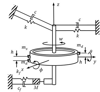
In Eq. (11), refers to Rotary shaft itself damping, refers to Stiffness coefficient, refers to unbalanced amount, , , , – refer to Support structure film force. , refer to Damping and stiffness coefficients of the ground support structure. When the foundation is loose, it can be expressed as:
By the Eqs. (11) and (12), it can be known that the flywheel rotor is a nonlinear vibration system with piecewise linear stiffness and damping in the working process, and the characteristics of the flywheel rotor are very complex.
In fact, all disturbances are coupled together to output disturbance force and torque. The following is the establishment of the disturbance model of flywheel components to analyze vibration of transfer law.
4. Flywheel component disturbance model
From the analysis above, the flywheel vibration can be decomposed into radial vibration force and vibration torque. To analyze the vibration transfer law, the dynamic model of the flywheel component is established:
Flywheel component coordinate system is , reference coordinate system is , the origins of the two coordinate systems are located in the center of the rotor and the root of the shaft respectively, and the initial positional relation is shown in Fig. 8. The inertia product of the body coordinate system is:
In Fig. 8, is Equatorial moment of inertia, is Polar moment of inertia.
Fig. 8Flywheel component coordinate system
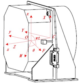
According to the theories of gyro mechanics and analysis mechanics, the flywheel radial kinetic equation is along with radial translation and rotate around [21].They are represented as:
In above formula, and are the force of the rotor center in and direction which has the per unit displacement. and are the force of the rotor center in and direction which has a unit rotation. and are the torque of the rotor center around and axis which has a unit rotation. and are the torque of the rotor center in and direction which has the per unit displacement., and , are the corresponding damping force and torque.
According to the relationship of the two coordinate systems, the vibration force and torque on the rotor base can be obtained:
In Eqs. (16)-(18), after Laplace transform, the function relation between the vibration excitation at the mass center, the radial disturbance force and torque of the flywheel component is obtained:
where, is Vibration transfer function.
5. Simulations and experiments
In Section 4, the flywheel micro vibration transfer function is derived. To explore the key factors that affect the quality of the pictures taking in space and then guide the satellite structure optimization design and vibration isolation compensation of the later type of improved satellite or other same type of satellites. Simulations and experiments are carried out under the flywheel stable working spinning speed 2800 rev/min, and the results are also discussed.
5.1. Simulations
For the target satellite, the flywheel’s parameters are shown in Table 2. These parameters are got from manufacturer except flywheel rotary inertia, flywheel rotor’s rotary inertia in horizontal and stiffness coefficient. The flywheel rotary inertia and flywheel rotor’s rotary inertia in horizontal are obtained by computing under supposing flywheel is a disc configuration. Stiffness coefficient is computed under single-degree-of-freedom-system.
Fig. 9Disturbance characters in simulation results
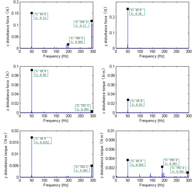
For flywheel working spinning speed 2800 rev/min, the simulation force and torque disturbance characters within 300 Hz according to the parameters in Table 2 are shown in Fig. 9. There is a harmonic at 48.6 Hz, and a series of peaks around the 190.4 Hz and 285.4 Hz.
Table 2Flywheel’s parameters in a high resolution satellite
Parameters | Value |
Max rotate speed | ≤ 4000 rev/min |
Working rotate speed | ± 2800 rev/min |
Flywheel mass | 2.25 kg |
Flywheel rotor mass | 1.02 kg |
Flywheel rotary inertia | 0.0097 kgm2 |
Flywheel rotor rotary inertia in horizontal | 0.00205 kgm2 |
Flywheel rotor rotary inertia along vertical | 0.00408 kgm2 |
Static imbalance | < 0.189 gcm |
Dynamic imbalance | < 0.123 gcm |
Natural frequency | 200 Hz; 100 Hz; 100 Hz |
Stiffness coefficient | 2.85e6 N/m; 2.85e6 N/m; 5.6e5 N/m |
5.2. Flywheel test
The flywheel component was installed on the test bench which located on the air bearing platform, and the disturbance test was carried out in the ultra-clean environment laboratory. The test site is shown in Fig. 2. The flywheel disturbing force and disturbance torque characteristics along the direction of , and respectively tested by using the model HR-FP3402 force plate with six component quartz. The sensor sampling frequency is 5 KHz. The testing process includes speeding up the flywheel from 0 rpm (Rev Per Minute) to the specified speed, deceleration to 0 rpm after holding 15 s, and the single test time lasts 100 s.
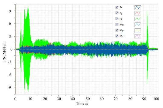
The typical response curves of flywheel disturbance in time domain are shown in Fig. 10. In time domain disturbance force is within 2 N magnitude, and the disturbing torque is with 1.5 N·m magnitude.
Fig. 10Typical response curve of flywheel test in time domain
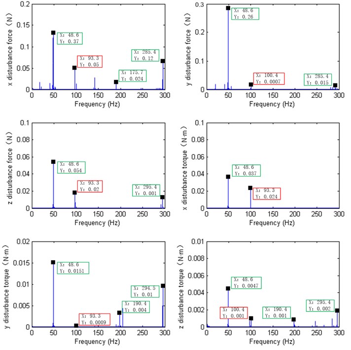
When the satellite is in the position of the push broom imaging, it keeps the attitude steady, and the working speed of the flywheel is constant. So, it is necessary to analyze the disturbance response characteristics when the flywheel is in its stable speed. To compare the simulation results, the flywheel test date at stable working spinning speed 2800 rev/min are extracted. Signal processing [22, 23] of the disturbance data, the force and torque disturbance characters within 300 Hz in frequency domain are shown in Fig. 11.
According to Fig. 11, there is another series of peaks around 90-100 Hz except the harmonics around 48.6 Hz, 190.4 Hz and 285.4 Hz. It is the flywheel structural modal amplification that caused by flywheel disturbance when flywheel spinning. It also means that the flywheel’s infrastructure should be more inflexible especially around 90-100 Hz.
As for the harmonics around 48.6 Hz, 190.4 Hz and 285.4 Hz that both exist in simulation results and test results, which will be effect the quality of the high-resolution satellite if without effective damping measures in orbit.
Fig. 11Disturbance characters in test results after signal processing
6. Conclusions
1) Due to the flywheel rotor affected by nonlinear factors during the working process, some small high order harmonics occur at the outside of the rotating speed frequency.
2) The rotor has a nonlinear vibration in the process of local collision friction, and there are some high harmonics in spectrogram in addition to its own rotating frequency.
3) The rotor working process is a nonlinear vibration system with piecewise linear stiffness and damping when the support base is loose.
4) If the bearing is damaged, it will bring a new harmonic wave, leading to an increasing harmonic wave number. The harmonic component is not the same, even if the same model of the different products.
5) The disturbance force of flywheel components is 2 N magnitude and the torque of disturbance is 1.5 N·m magnitude in time domain. The flywheel’s infrastructure should be more inflexible especially around 90-100 Hz. For this target high resolution optical satellite, there should be effective damping measures around 48.6 Hz, 190.4 Hz and 285.4 Hz to decrease the flywheel disturbance to guarantee the high precision of the satellite.
6) The larger the flywheel vibration disturbance force and torque are, the more concentrated the harmonic is. The satellite structure should be further optimized for follow-up satellite or similar satellite design, vibration isolation design of flywheel and isolation design for optical load.
References
-
Gary Matthews, et al. A paradigm shift to enable more cost effective space science telescope missions in the upcoming decades. Proceedings of SPIE, 2010.
-
Tan Tian Le, Zh C., Zhu Dong Fang, et al. Overview of micro-vibration testing, isolation and suppression technology for spacecraft. Aerospace Shanghai, Vol. 31, 2014, p. 36-45.
-
Zhang Qing, Jun W. G., Zh G. Micro-vibration attenuation methods and key techniques for optical remote sensing satellite. Journal of Astronautics, Vol. 36, Issue 2, 2015, p. 125-132.
-
Jin L., Xu S. J. Under actuated spacecraft angular velocity stabilization and three-axis attitude stabilization using two single gimbal control moment gyros. Acta Mechanica Sinica, Vol. 26, Issue 2, 2010, p. 278-288.
-
Wang Guang Yuan, et al. Data analysis of micro-vibration on-orbit measurement for remote sensing satellite. Journal of Astronautics, Vol. 36, Issue 3, 2015, p. 261-267.
-
Hyde T. T., et al. Integrated modeling activities for the James Webb Space Telescope. Proceedings of SPIE, 2004.
-
Bronowicki A. J. Vibration isolator for large space telescopes. Journal of Spacecraft and Rockets, Vol. 43, Issue 1, 2006, p. 45-53.
-
Ryabov I. M., et al. The choice of a mass of dynamical vibration absorber of the wheel. Automotive Industry, Vol. 8, 2013, p. 15-17.
-
Ryabov I. M., Kovalev A. M., Chernyshov K. V., Rasulov T. M. Dynamical absorber of vertical oscillations of a vehicle wheel integrated with design of the disk brake mechanism. Automotive Industry, Vol. 4, 2015, p. 17-19.
-
Wang Hong Juan, et al. Space camera image degradation induced by satellite micro-vibration. Acta Photonica Sinica, Vol. 42, Issue 10, 2013, p. 1212-1217.
-
Huang Ting Xuan, et al. Dynamic modeling of combined reaction wheel and vibration isolation platform system. Journal of Beijing University of Aeronautics and Astronautics, Vol. 39, Issue 1, 2013, p. 120-125.
-
Zhang Weiya, et al. Dynamical investigation and parameter stability region analysis of a flywheel energy storage system in charging mode. Chinese Physics B, Vol. 9, 2013, p. 619-632.
-
Heimel H. Space wheel microvibration-sources. Appearance, Countermeasures, ESA GNC2011, Karlovy Vary, 2011.
-
Wang Zeyu, et al. The jitter measurement and analysis for a remote sensing satellite platform. Spacecraft Environment Engineering, Vol. 32, Issue 3, 2015, p. 278-285.
-
Yang Zhaohua, et al. Earth-observation satellite attitude control using passive and active hybrid magnetically suspended flywheels. Journal of Beijing Institute of Technology, Vol. 2, 2014, p. 226-234.
-
Tian Lin, X. S. Attitude control considering variable input saturation limit for a spacecraft equipped with flywheels. Chinese Journal of Aeronautics, Vol. 3, 2012, p. 437-445.
-
Liu K. C., Maghami P., Blaurock C. Reaction wheel disturbance modeling, jitter analysis, and validation tests for solar dynamics observatory. AIAA Guidance, Navigation and Control Conference, 2008.
-
Ryabov I. M., Chernyshov K. V., Pozdeev A. V. Types of designs of inertial-frictional shock absorbers, modeling and testing. Tractors and Farm Machinery, Vol. 4, 2013, p. 23-26.
-
Miller S. E., Kirchman P., Sudey J. Reaction wheel operational impacts on the GOES-N jitter environment. AIAA Guidance, Navigation and Control Conference, 2007.
-
Firth J., Black J. Vibration Interaction in a Multiple Flywheel System. Air Force Institute of Technology Air University, 2011.
-
Zhang Jiyang, et al. Micro vibration characteristics of flywheels and its vibration control approaches. Aerospace Control and Application, Vol. 40, Issue 5, 2014, p. 1-7.
-
Li Yongbo, et al. An improvement EMD method based on the optimized rational Hermite interpolation approach and its application to gear fault diagnosis. Measurement, Vol. 63, 2015, p. 330-345.
-
Li Yongbo, et al. Early fault feature extraction of rolling bearing based on ICD and tunable Q-factor wavelet transform. Mechanical Systems and Signal Processing, Vol. 86, 2017, p. 204-223.
Cited by
About this article
The authors would like to thank the financial support of the National Natural Science Foundation for Young Scholar of China (No. 61505203) and Youth Innovation Promotion Association CAS (No. 2011171).
Tan Luyang planned the test procedure which provide experimental contribution to this paper. Kong Lin analyzed the test data and offered guidance during the paper revision process. Wang Dong and Yang Hongbo both are my PhD. Supervises that they provided guidance on writing this paper. What’s more, logical organization of the paper is also improved during the guidance.
