Abstract
To predict accurate micro-vibration produced by a spaceborne payload mounted pulse tube cryocooler (PTC), a coupled disturbance analysis of cryocooler with flexible support structures have been discussed and investigated. A coupled transfer function matrix is introduced by improving the traditional disturbance analysis. According to the coupling disturbance relationship between the source and supporting structure, microvibration input load is accurately obtained. Based on the finite element model of the space camera, the performance of optical system is analyzed. Compared to the decoupled method, this coupled method can accurately predict the local transfer characteristics between cryocooler and interface.
1. Introduction
Microvibration disturbances affect the pointing of precision payloads, which have become increasingly important in the most advanced space missions. Mechanical cryocooler is one of the main disturbance sources of on-orbit spacecraft. It causes problems for sensitive payloads such as high resolution cameras where high pointing stability is required, has made analysis and control of microvibrations relevant for a larger number of satellites [1, 2].
Because of the omission of any moving parts in the cold head, pulse tube cryocooler has become prevalent in practice. Another point of reducing the level of vibration is to run coolers as back-to-back synchronized pairs, such that the forces of one cooler will balance the forces generated by the other [3, 4]. However, the residual vibration export originated from unavoidable technological tolerances, natural wear and contamination cannot be completely eliminated, which may cause severe problems for the operation of high quality space devices.
The exported vibration of a PTC is caused by the acceleration of the moving masses during its periodic motion [5]. There are two fundamental approaches that analysis the vibrational energy to the camera system. The first method relies on physically modeling the plant that causes the vibration and to assign realistic values to the physical parameters of the model. The second approach consists in creating an empirical model of the disturbance via the analysis of experimental test data. Both approaches are explored for the cryocooler disturbance model [6-8].
Microvibration disturbances are typically measured in a “blocked” configuration, and load transducers are used to measure the resulting disturbance loads at the interface [9, 10]. However, this method is not an accurate representation of the coupled boundary conditions that occur when the PTC is mounted to a structure. With the aim to analytically reproduce the coupled dynamics, a dynamic mass method was developed to evaluate the coupled performance [11-13]. Although the results are accurate, this method is significantly challenging in terms of test configuration and computational effort.
This paper investigates the coupled dynamics between a pulse tube cryocooler and its flexible supporting structure on space camera. Cryocooler microvibrations are measured experimentally by hard-mounted condition as direct inputs to predict spacecraft performance. The coupled cryocooler-supporting structure model is derived using “force filters” method. Finally, characteristics of the coupled disturbance analysis are discussed. Some conclusions are summarized that this coupled disturbance analysis is efficient to analyze the microvibration in space platform.
2. Dynamic coupling theory
2.1. Problem of coupled dynamics
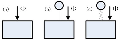
Fig. 1 illustrates the three different cases for spacecraft microvibration analysis. The model Fig. 1(a) presents the source not included in the system and hard mounted loads directly applied to the supporting structure. In this case, the microvibrations applied as direct input generally overestimated the coupled loads and response as expected. In model Fig. 1(b), the source represented as a lumped mass connected rigidly to the supporting structure. Due to its rigidity the stiff support behaves as a lumped mass in the range of frequency analysis, which failed to simulate the cryocooler structural modes due to lack of cryocooler dynamics implemented in the model, hence its internal dynamics do not affect the response. Therefore, the coupled effect between the source and the supporting structure are limited in this case. The model Fig. 1(c) presents an increased agreement throughout the frequency band. It is not only able to reproduce the coupled dynamics between the cryocooler and the supporting structure but also accurately simulate the cooler dynamics.
Fig. 1Disturbance analysis cases: a) no source; b) source as lumped mass; c) source dynamic mass
2.2. Coupled disturbance analysis
In order to motivate this coupled dynamics, a two degree of freedom sample problem is studied. If the input-output relationship of system is:
where is displacement response of supporting structure, is the disturbance force of source, is transfer function.
Fig. 2Decoupled disturbance approximate model
Consider the two DOF system shown in Fig. 2, where and represent a simplified one DOF of spacecraft and and represent a simplified cryocooler. This figure demonstrates a simplified model of decoupled disturbance. Decoupled input-output relationships can be expressed by:
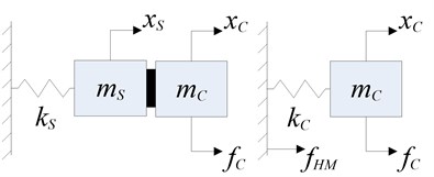
Fig. 3Coupled disturbance approximate model
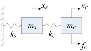
Fig. 3 represents a coupled disturbance system, input-output relationships can be expressed by:
By comparing the input-output relation of coupled disturbance and decoupled disturbance, it is known that the decoupled analysis overestimate the mass including both components. However, when the mass of camera is much higher than that of microvibration source, the transfer function of these two methods is relatively close.
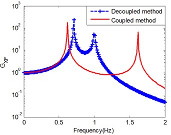
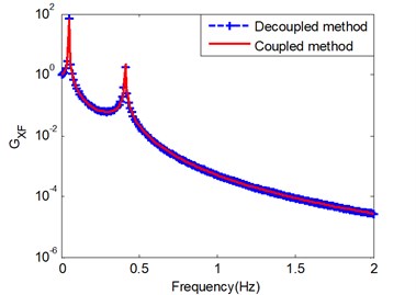
Fig. 4 is the frequency response function of coupled and decoupled analysis for 1 N/m. It is shown that the results are essentially different when the system parameters of two DOF are the equal. When the mass deflection rate is greater (400 Kg, 6 Kg), the results of these two method tend to be the same. However, one must be cautious in extending this conclusion to more complex and multi-DOF systems, the decoupled analysis method is no longer applicable.
Fig. 4Frequency response function results: a) mS=mC= 1 Kg; b) mS= 400 Kg, mC= 6 Kg
a)
b)
3. Coupled disturbance analysis in space camera
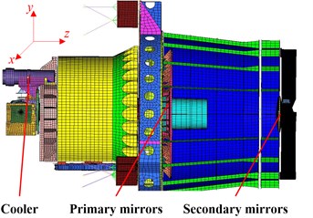
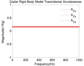
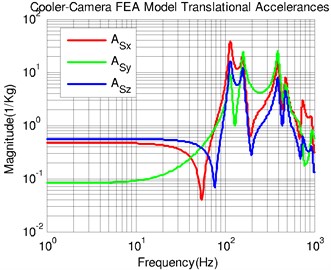
A force filter method was introduced to evaluate the coupled performance between cooler and camera [9]. Fig. 5(a) shows a rigid-body model of cooler compressor and Fig. 5(b) is the FE model of camera assembly. “Rigid-cooler, Model-camera” is used to estimate the desired translational accelerances of each body. Since the cooler driving point accelerances are frequency-independent, they have constant magnitudes equal to the inverse of the compressor mass, shown in Fig. 6(a). The Model-based driving point accelerances shows in Fig. 6(b), which is obtained from its FE model applying unit forces at one DOF through an existing finite element model of camera (Fig. 5(b)). Since the camera mass is about 400 Kg, its low-frequency accelerance should tend toward 2.5×10⁻³ Kg-1. The Model-based accelerances in Fig. 6(b) are consistent with this.
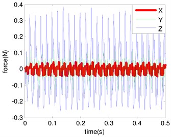
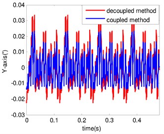
We use a semiempirical methodology to predict the performance of camera. A preliminary test campaign under blocked condition was conducted to assess the loads of cryocooer. The force response is shown in Fig. 7(a), which is used to predict camera performance. The center line of primary and secondary mirrors is considered as the principal optic axis of the camera. Microvibration mainly causes optic axis to produce the lateral deviation. The predicted angular displacement results by using decoupled and coupled disturbance analysis are shown in Fig. 7(b). It is important note that the coupled disturbances can improve the predictions.
Fig. 5Model of space camera: a) rigid-body model of cooler; b) FE model of camera
a)
b)
Fig. 6Model-based accelerances: a) rigid-cooler accelerances; b) model-camera accelerances
a)
b)
Fig. 7Microvibration response: a) disturbance force of cooler; b) angular displacement of optic axis
a)
b)
4. Conclusions
The coupled dynamics of a PTC mounted on a flexible supporting structure were discussed in this work. Decoupled and coupled disturbance modeling methods were firstly used to understand the coupled disturbance mechanism. The predictions derived from the traditional approach using forces from the hard-mounted boundary condition as direct input ignore the coupled dynamics characteristics. The coupled disturbance analysis using force filters method has been used, which is applicated to a PTC in space camera. The results show that the coupled disturbance method can improve the analysis results.
References
-
Tomaru T., Suzuki T., Haruyama T., et al. Vibration analysis of cryocoolers. Cryogenics, Vol. 44, 2004, p. 309-317.
-
Oh H. U., Lee K. J., Jo M. S. A passive launch and on-orbit vibration isolation system for the spaceborne cryocooler. Aerospace Science and Technology, Vol. 28, 2013, p. 324-331.
-
Houlei Chen, Nana Xu, Jingtao Liang, et al. Vibration reduction of pulse tube cryocooler driven by single piston compressor. Cryogenics, Vol. 52, 2012, p. 816-818.
-
Riabzev S. V., Veprik A., Vilenchik H., et al. Control of dynamic disturbances produced by a pulse tube refrigerator in a vibration-sensitive instrumentation. Cryogenics, Vol. 49, 2009, p. 7-11.
-
Riabzev S. V., Veprik A. M., Vilenchik H. S., et al. Vibration generation in a pulse tube refrigerator. Cryogenics, Vol. 49, 2009, p. 1-6.
-
Colbert R., Nguyen T., Raab J., et al. Self-induced vibration of NGAS space pulse tube coolers. International Cryocooler Conference, 2008.
-
Ikushima Y., Rui Li, Tomaru T., et al. Ultra-low-vibration pulse-tube cryocooler system-cooling capacity and vibration. Cryogenics, Vol. 48, 2008, p. 406-412.
-
Wolfe D. W., Kirkconnell C. S., Fleischman G. L., et al. Jitter suppression techniques for mechanical cryocooler-induced disturbances. Proceedings SPIE 7087, Remote Sensing System Engineering, 2008.
-
Elias L., Dekens F., Basdogan I., et al. Methodology for modeling the mechanical interaction between a reaction wheel and a flexible structure. Proceedings of SPIE Astronomical Telescopes and Instrumentation Conference, Waikoloa, 2003, p. 541-555.
-
Addari D., Aglietti G. S., Remedia M. Experimental and numerical investigation of coupled microvibration dynamics for satellite reaction wheels. Journal of Sound and Vibration, Vol. 386, 2017, p. 225-241.
-
Elias L. M., Miller D. W. A coupled disturbance analysis method using dynamic mass measurement techniques. Proceedings of the 43rd Annual AIAA/ASME/ASCE/AHS/ASC Structures, Structural Dynamics, and Materials Conference, 2002, p. 22-25.
-
Zhe Zhang, Aglietti G. S., Weijia Ren. Coupled microvibration analysis of a reaction wheel assembly including gyroscopic effects in its accelerance. Journal of Sound and Vibration, Vol. 332, 2013, p. 5748-5765.
-
Basdogan I., Elias L. M., Dekens F., et al. Predicting the optical performance of the space interferometry mission using a modeling, testing, and validation methodology. Journal of Vibration and Acoustics, Vol. 129, 2007, p. 148-157.
About this article

