Abstract
In the launching process, the spacecraft situated in an extreme dynamic environment may withstand by various dynamic loads such as noise loading in the fairing, motor excited vibration, shock of the separation devices, etc. To achieve a successful launching, the device called whole-spacecraft vibration isolator is usually installed between the adapter and the spacecraft to prevent the later from being damage. A novel WSVI device, which composed of supporting leaf springs, voice coil motors (VCM) and actuator supports, is designed to suppress the structural vibration of the spacecraft in this paper. The novel WSVI device features small space footprint and light weight, and satisfy the design requirement of vibration isolation without changing of the Payload Adaptor Fitting structure. A dynamic model of the WSVI device is established to evaluate the performance of the system. The dynamic characteristics and responses subjected to external excitation are studied for the spacecraft installed with WSVI. The vibration isolation performance is analyzed after turning the VCM into passive dampers. The results show that the novel WSVI device, which can reduce the amplitude of vibration response of the spacecraft significantly, is valid for vibration suppression of the spacecraft.
1. Introduction
During the launching process of the rocket, the spacecraft may suffer an extreme dynamic environment. The launching dynamic loads include low frequency dynamic loads such as liftoff, motor excitation, buffet, motor starts and shutoffs. Spacecraft are also subjected to shock loads due to staging, spacecraft separation, and fairing separation [1]. These dynamic loads may cause damage to the structure of the spacecraft, which affect the normal function of the devices carried by the spacecraft. The whole-spacecraft vibration isolation (WSVI) technique using a vibration isolation device to connect the rocket and spacecraft, instead of traditional rigid connection by Payload Adaptor Fitting (PAF) structure. By using this technique, the dynamic loads transferred to the spacecraft can be isolated, and the launch environment will be improved significantly.
As an important technology affecting the development of space technology, whole-spacecraft isolation has drawn attention of researchers for a long time. On the initiative of United States Air Force Research Laboratory (AFRL) and Space Vehicles Directorate, CSA Engineering Inc [2-5] began the research about whole-spacecraft isolation and shock resistance test of the spacecraft. They have proposed the SoftRide UniFlex and SoftRide MultiFlex WSVI systems. In order to solve the problem on the dimensional limit of the SoftRide MultiFlex and further enhance the performance of the dampers, a SoftRide OmniFlex isolation system was developed by CSA Engineering Inc in 2008 [6-8]. And now the SoftRide OmniFlex platform has become the main solution to WSVI problem of CSA Engineering Inc. In the frame of the ESA GPS program European Aeronautic Defense & Space (EADS) [9, 10] has developed an active payload adaptor for Ariane 5. And the proposed system is a truss structure with 24 active struts in the load path using piezo-ceramics as actuator. The active payload adaptor is thought to replace the conventional passive payload adaptors, for instance, the conical Carbon Fiber Reinforced Plastics (CFRP) shell structures. In 2004, the AFRL cooperated with ATA Engineering Inc developed a Multi-Payload Adapter (MPA) for the Peacekeeper Space Launch Vehicle [11]. ATA’s MPA consists of an annular flat plate that has top and bottom face sheets separated by radial ribs and close-out rings. Also, this vibration isolator has the advantage of small footprint and strong commonality but has barely lateral vibration isolation ability. Besides, Scholars like Griffin, Khorrami [12, 13], etc. also have proposed different WSVI ideas.
The WSVI schemes reported in the literature were mainly focused on the passive vibration isolation, the isolation performance of which may not be very effective in the low frequency region. A novel WSVI device, composed of supporting leaf springs, voice coil motors and actuator supports, is designed to realize active vibration isolation of the spacecraft. The proposed device is not only designed to have the feature of small space footprint and light weight, but also satisfy the design requirement of vibration isolation without changing of the PAF structure. The isolation system is elegant in its simplicity, which can be used universally for different type of spacecraft.
2. Electromagnetic actuator
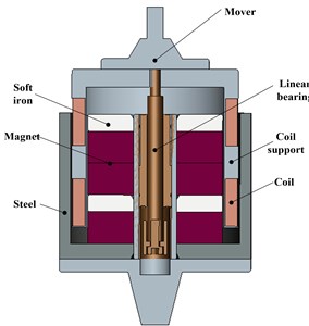
Compared with other types of actuators, electromagnetic actuator (also called VCM) has the advantages of compact structure, fast response, wide control frequency band, large actuating displacement, easy assembly, large ratio of output force between quality and volume of the actuator, etc. It is a new type of actuator integration of mechanical, electrical and magnetic components. What is more, only electric energy provided for its normal operation, which has a highly engineering application value in aerospace engineering where the electric power is widely used. The structure of the electromagnetic actuator adopted in this thesis is as shown in Fig. 1. The cutaway view depicted in Fig. 1 illustrates a unique configuration inside the VCM, where the soft iron and magnet are interval arranged along the central linear bearing to ensure a maximum performance of the magnet.
Fig. 1Cutaway view of the electromagnetic actuator
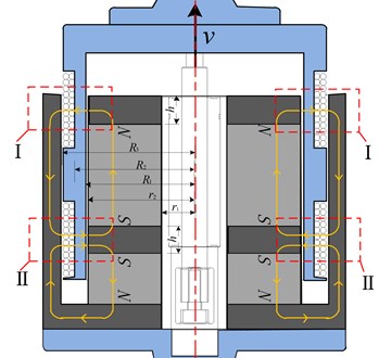
In order to derivate the driving force expression of the VCM, Maxwell 16.0 is utilized to simulate and analyze the magnetic field of the actuator, and the magnetic field lines and intensity distribution are shown in Fig. 2. It is shown that magnet steel with a high magnetic permeability can constrain the distribution of the magnetic field line, prevent it from diverging. The special shape and configuration of the permanent magnet steel contribute to a regular magnetic field in the actuator, where magnetic field line mainly along the area I and II when it crosses the air gap. Ideally, make a hypothesis that all the magnetic field line pass through the air gap with a height of (the thickness of the soft iron), and perpendicular to the coils, as shown in Fig. 3.
Fig. 2The magnetic field lines and intensity distribution of the actuator
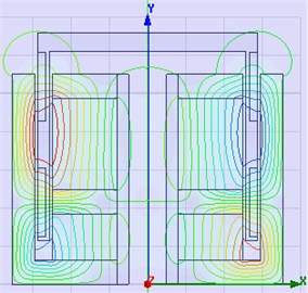
a) Magnetic field lines
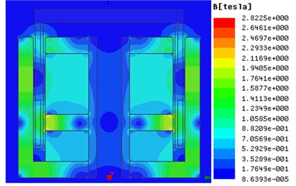
b) Magnetic intensity distribution
According to the Gauss's law for magnetism, the total magnetic flux through a closed surface is equal to zero. The equation is defined by:
Hence in area I and II we can get:
Then:
where is the remanence intensity of the permanent magnet, and are the magnetic flux density of area I and II, respectively.
Fig. 3Magnetic induction line in the actuator
By the Ampere theorem, Electric conductor in magnetic field will be affected by force, which contribute to the constitutive equation of the VCM:
where is the number of the coils, is the remanence intensity, is the length of per coil, is the current of the coil. Hence, the driving force of the actuator can be obtained from Eq. (4). For convenient we define (N/A) as the force constant of the actuator, which is the main parameter that reflecting the performance of actuator comprehensively.
3. The novel WSVI device
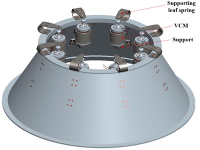
PAFs are usually adopted to connect the launcher and the payload. The WSVI system (Fig. 4) is proposed to replace the PAF with passive or active adaptor so that the dynamic load transmit to the payload can be attenuated. The novel WSVI device proposed in this paper is mainly composed of supporting leaf springs, electromagnetic actuators, actuator supports, etc. The supporting leaf spring is a U-type connector, the upper limb of which is connected to the bottom of the satellite and the lower limb is connected to the top of the PAF. All the leaf springs provide the support stiffness for the isolation platform. The electromagnetic actuators installed in the interior of the PAF, the mover connect to cantilever end of the leaf spring, and the stator fixed on the support. The supports also fixed in the interior of the PAF by bolted connection, which are used for supporting of the electromagnetic actuators. The supporting leaf spring, electromagnetic actuator and support form an actuation unit. The whole WSVI platform composed of eight actuation units, and uniformly installed in circumference direction of the PAF. The assembled WSVI platform is as shown in Fig. 5.
Fig. 4The WSVI system
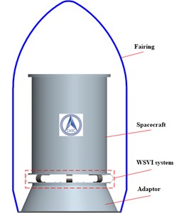
Fig. 5The proposed WSVI platform
4. System modeling
4.1. Coordinate frames
The visual representation of the mathematical model of the WSVI system is shown in Fig. 6. The spacecraft is assumed to be a rigid body (with the consideration that the solar panels are folded during the launching process) supported from below by 8 suspension legs which connect the top of the PAF to the bottom of the spacecraft. A single suspension leg will be defined here as one leaf spring and one electromagnetic actuator. The global coordinate frame is set with the orthonormal and axes parallel to the bottom of the PAF and the axis normal to the bottom of the PAF.
Fig. 6Mathematical model of the system
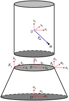
The origin of the body coordinate frame is located at the center of gravity (CG) of the spacecraft. The generalized displacement vector of the body coordinate frame in the global coordinate frame is defined as:
where is the translational displacement vector correspond to the displacements about the , , axes. is the rotational displacement vector corresponding to the rotations about the , , axes.
The generalized displacement vector of the body coordinate frame in the global coordinate frame is defined as:
where is the translational displacement vector correspond to the displacements about the , , axes, is the rotational displacement vector corresponding to the rotations about the , , axes.
Let be the th leaf spring coordinate frame and be the th actuator coordinate frame. Transformation between different coordinates can be described by transformation matrix, where is the transformation matrix from the local fixed frame to the global frame . Euler angles, , can be used to describe the transformation of the th leaf spring, and they are corresponding to the rotations about the , , axes, respectively. Let rotation about -- in turn, here, , and , then the elementary rotation matrices can be written as:
And then the expression of the transformation matrix is:
where , . is an orthogonal matrix, thus . The transformation matrices and are similarly defined.
In fact, the rotational displacement of the spacecraft is very small, namely the rotational displacements of body frame with respect to the global frame are assumed to be small, besides the body frame and global frame share the same initial orientation, then the position vector of any point n fixed in the body frame can be expressed in the global frame as:
where is the position vector from bode frame to point , and is the skew-symmetric matrix defined for vector cross product operation given as:
The translational displacement of any point fixed in the body frame can be expressed in the global frame as:
4.2. Dynamic equations of the system
The dynamic equation of the system can be written as:
where is the generalized mass matrix, and , , are the generalized global forces on the body frame due to the leaf springs, actuators, and gravity, respectively. The generalized mass matrix can be expressed in the global frame as:
where , and , in which is the mass of the payload, is the moment of inertia matrix that the spacecraft with respect to its barycenter, is the transition of moment of inertia matrix, is the moment of inertia matrix that the spacecraft with respect to global frame .
The generalized force vector due to gravity applied to the body frame can be written as:
The stiffness of th leaf spring defined in the local frame can be written as:
where , , are the lateral and longitudinal stiffness of the leaf spring, along , , , respectively, as shown in Fig. 7(a) and:
The generalized force vector due to all leaf springs applied to the body frame can be expressed as:
where , and , are the force and torque vectors applied to the body frame due to the th leaf spring, respectively. Then, the force vector forth leaf spring can be written as:
And the torque vector is:
Hence, the generalized force vector can be written as:
where is the generalized global stiffness matrix, and:
Fig. 7Coordinate frame of leaf spring and actuator
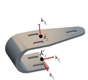
a) Coordinate frame of th leaf spring
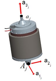
b) Coordinate frame of th actuator
In this WSVI scheme, the electromagnetic actuator vertically mounted on the support by universal spherical joints which allows only axial force to be transmitted through the actuator. Hence, the force of the th electromagnetic actuator defined in its local coordinate frame (see Fig. 7(b)) can be expressed as:
where , is the force constant of the electromagnetic actuator, is the drive current in th electromagnetic actuator. The generalized global force vector due to all actuators applied to the body frame can be described as:
where the generalized force vector due to th electromagnetic actuator is expressed as:
Let , and . Then Eq. (25) can be written as:
Hence, Eq. (14) can be written as:
4.3. State space equation of the system
The equation of motion of the system can be expressed in state space form, namely:
where is the state vector, is the external disturbances, and is the system input. Then, the system matrix is:
the input matrix is:
and the disturbance matrix is:
Up to now, the kinematical equations of the WSVI system are described mathematically and the dynamic equations of the proposed WSVI system are established. Moreover, the corresponding state-space expression of the system is developed for vibration analysis and controller design in the future.
5. Dynamic characteristics analysis of the system
5.1. Dynamic response
A scaled-down model of the spacecraft with WSVI device has been designed for further investigation. The physical parameters of the spacecraft model and the WSVI device are listed in Table 1.
Substituting the parameters listed in Table 1 into Eq. (28), the natural frequencies of the system are calculated and listed in Table 2, in which the first order frequency correspond to the rolling modal around the lateral axis, the second order frequency is the longitudinal vibration along the rocket axis, the third order frequency is the lateral vibration normal to the rocket axis, and the fourth frequency is the torsional vibration about the vertical axis.
Table 1Physics parameters of the system
Physics parameter | Value |
Mass of satellite | 23.46 kg |
Moment inertia of the satellite | Diag (0.94 0.94 1.02) kg·m2 |
Distance between body frame to global frame | 0.788 m |
Distance between body frame to the bottom of the satellite | 0.456 m |
Leaf spring stiffness | Diag (3.3e5 3e5 2e5) N/m |
Force constant of the actuator | 41 N/A |
Gravitational acceleration | 9.8 m/s² |
Passive damping coefficient | 10 N·s/m |
Table 2Natural frequencies of the system
Items | First order | Second order | Third order | Fourth order |
Frequency (Hz) | 51.35 | 261.15 | 376.90 | 418.39 |
The dynamic loads from the rocket are mainly considered here for the dynamic response analysis of the system. Assume that , namely, only consider the lateral disturbance, the response of the system then can be obtained as shown in Fig. 8. The result shows that the lateral disturbance not only excite the lateral response (Fig. 8(a)), but also excite the rotational response (Fig. 8(b)) and longitudinal response (Fig. 8(c)) of the system.
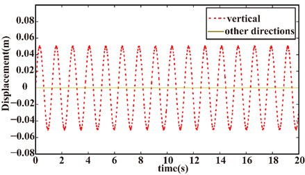
Fig. 9 shows the response of the system due to the longitudinal excitation. It is noted that only the vertical response be excited (red line in Fig. 9), as a result of the assumption that the system is a symmetrical one.
Fig. 8Response due to lateral excitation: a) lateral response, b) rotational response, c) longitudinal response, d) responses in other directions)
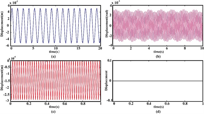
Fig. 9Response due to vertical excitation
5.2. Isolation performance under passive condition
According to Faraday’s Law of Electromagnetic Induction, the electromotive force () and current () are induced when the closed coils moves in magnetic field. After substituting them into Eq. (4) the Ampere’s force then can be written as:
where is the resistance of the coils, is relative velocity of coils.
Thus, the electromagnetic actuator can equivalent to a viscous damper, when shorts out the coil of the actuator. And the damping coefficient:
is a constant only related to the physic parameters of the actuator. Then, the damping force due to th damper can be written in the global coordinate frame as:
and the total damping force then be described as:
Substituting Eq. (34) and Eq. (35) into Eq. (28), the dynamic equation of the damped system can be written as:
Fig. 10 shows the response of the system subject to a fixed frequency excitation (N) in the vertical direction, the dotted line represents the response of the original system and the solid line represent the response of the damped system, respectively. It is noted that the response of the damped system has a lower magnitude compared to that of the original system. The free responses with an initial displacement 0.05 m and initial velocity 0.05 m/s, are shown in Fig. 11. It can be easily observed from Fig. 11 that the damped system attenuated rapidly.
Fig. 10Response under vertical excitation
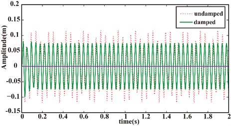
Fig. 11Free response in vertical direction
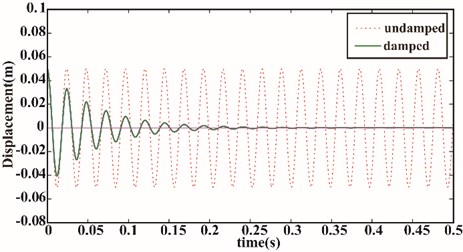
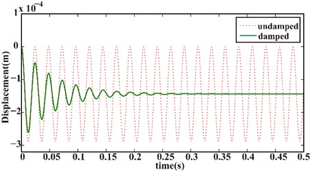
Fig. 12 to Fig. 14 shows that the magnitudes of the response of the system with a fixed frequency excitation (N) in the lateral direction, and a lower magnitude obtained after considering the electromagnetic damping.
Fig. 12Lateral response under lateral excitation
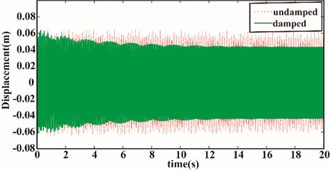
Fig. 13Rotational response under lateral excitation
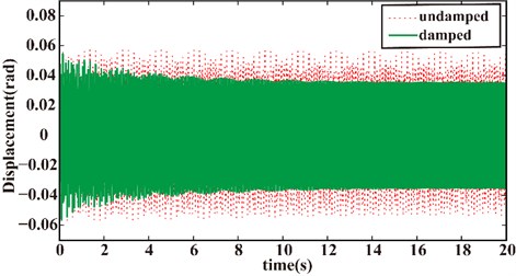
Fig. 14Vertical response under lateral excitation
The free responses with an initial displacement 0.05 m and initial velocity 0.05 m/s in the lateral direction are shown in Fig. 15 to Fig. 17, respectively. The damped system illustrated the same attenuation trend compared to the original system.
Fig. 15Lateral free response (with an initial displacement and velocity in lateral direction)
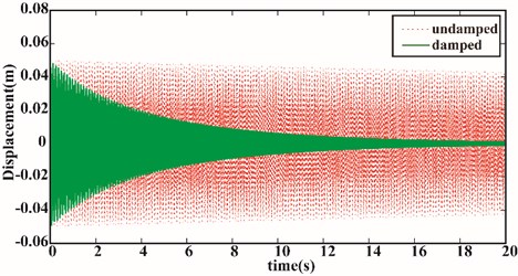
Fig. 16Rotational free response (with an initial displacement and velocity in lateral direction)
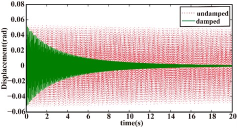
Fig. 17Vertical free response (with an initial displacement and velocity in lateral direction)
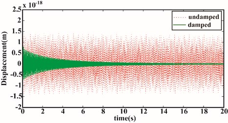
It is observed that the WSVI has a good isolation performance when considering the VCMs as viscous dampers. The response amplitude of the system can be suppressed effectively, and it is also noted that the system has a higher decay speed in vertical direction than lateral direction, this is because of the actuators are all mounted vertically, which lead to a larger damping force in the vertical direction.
6. Experimental analysis
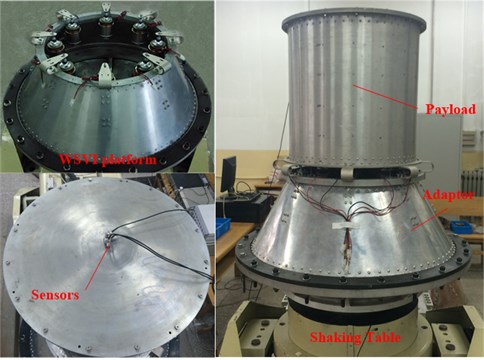
A scaling model is built, and an experimental setup is constructed (see Fig. 18), sinusoidal sweeping-frequency vibration tests were carried out on the experimental device in both lateral and longitudinal directions for further verification the isolation performance of the proposed WSVI platform. In the two experiment cases, the shaking table provides a sweeping acceleration signals from 5 Hz to 100 Hz with an amplitude of 1 m/s2 and 5 m/s2 respectively as the disturbances. The undamped and damped systems are tested in each case, where the undamped and damped system corresponding to the open and short circuit of the VCM, respectively. The amplitude-frequency responses captured from the two vibration experiments are presented in Fig. 19. It should be noted that, for better demonstrate the isolation perform of the WSVI platform the stiffness of the leaf springs employed in this experiment is lower than that of the simulation.
Fig. 18Photo of the WSVI platform and experiment set-up
It can be observed form the experiment results that in the lateral experiment case the amplitude at the resonance peak is significantly decreased from 29.15 m/s2 to 11.23 m/s2, and in the longitudinal experiment case the response at the resonance frequency of the system is attenuated from 88.88 m/s2 to 27.46 m/s2 due to the contribution of the electromagnetic damping.
Fig. 19Frequency response of the payload
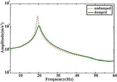
a) Lateral
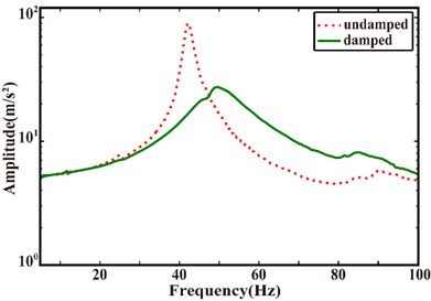
b) Longitudinal
7. Conclusions
In this work, a novel whole-spacecraft vibration isolation device has been developed based on the VCM. An analytical model for the generated force of the VCM is derived by applying the electromagnetic equations. Then, the structural features of the proposed WSVI device were illustrated and the kinematics equation for the system were formulated. The dynamic model and the state space equation of the system were developed for the study of the dynamic characteristics. In addition, the physics parameters of a scaled-down WSVI device were given and then, the natural frequency, the dynamic response under exogenous disturbances were obtained. Finally, based on the electromagnetism theorem, the electromagnetic actuator was turned into viscous damper, and the isolation performance of the WSVI system was verified though the simulation and experiment.
The newly proposed WSVI device features small space footprint, light weight. It can satisfy the design requirement of WSVI without changing of the PAF structure with its novel design. From the passive vibration isolation results, it is clear that the new WSVI device performed very well to reduce structure vibration transmitted to the spacecraft. What should be noted is that, this paper mainly discussed the passive isolation performance of the proposed device, the future research will focus on the investigation of active vibration isolation performance.
References
-
Johnson C. D., Wilke P. S. Protecting satellites from the dynamics of the launch environment. AIAA Space Conference and Exposition, Long Beach, California, 2003.
-
Johnson C. D., Wilke P. S., Grosserode P. J. Whole-spacecraft vibration isolation system for the GFO/Taurus mission. Symposium on Smart Structures and Materials, 1999, p. 175-185.
-
Johnson C. D., Wilke P. S., Darling K. R. Multi-axis whole-spacecraft vibration isolation for small launch vehicles. SPIE’s 8th Annual International Symposium on Smart Structures and Materials, 2001, p. 153-161.
-
Johnson C. D., Wilke P. S. Recent launches using the SoftRide whole-spacecraft vibration isolation system. AIAA Space Conference and Exposition, Albuquerque, New, Mexico, 2001.
-
Johnson C. D., Wilke P. S. Whole-spacecraft shock isolation system. SPIE’s 9th Annual International Symposium on Smart Structures and Materials, San Diego, CA, 2002.
-
Kern D. L., Gerace C. A. Implementation of a whole spacecraft isolation system for the OSTM/Jason 2 mission. Aerospace Conference, 2008, p.1-8.
-
Raman S. J., Paul S. W., Conor D. J. Rapid coupled loads analysis and spacecraft load reduction using SoftRide. 23rd Annual Conference on Small Satellites, 2009.
-
Johal R., Christensen J., Doud D. ORBCOMM generation 2 access to LEO on the falcon 9 using SoftRide, a case history. Conference on Small Satellites, 2012.
-
Rittweger A., Beig H., Konstanzer P., Dacal R. B. Active payload adaptor for Ariane 5. 56th International Astronautical Congress of the International Astronautical Federation, Fukuoka, Japan, 2005, p. 3654-3665.
-
Rittweger A., Beig H., Konstanzer P., Bureo Dacal R. Feasibility demonstration of an active payload adapter for Ariane 5. Proceedings of the European Conference on Spacecraft Structures, Materials and Mechanical Testing, Noordwijk, The Netherlands, 2005, p. 149.
-
Fram B. J., Thomas G. R., Fadick C. M. A multi-payload adapter for peacekeeper-based space launch vehicles. Space Conference and Exhibit, San Diego, California, 2004.
-
Griffin S. F., Sciulli D. Whole-Spacecraft Hybrid Isolation System for Launch Vehicles. U.S. Patent No. 6,135,390, 2000.
-
Khorrami F., Rastegar J. S., Erwin R. S. Three-degree-of-freedom adaptive-passive isolator for launch vehicle payloads. SPIE’s 7th Annual International Symposium on Smart Structures and Materials: International Society for Optics and Photonics, 2000, p. 164-175.
Cited by
About this article

The authors are grateful to the Foundation of Civil Astronautics and the Pre-research Foundation of General Armament Department of China for financial support in this study.
Jie Tang had the original idea for the study and drafted the manuscript. Dengqing Cao contributed to the guidance and revision work of the paper. Zhaohong Qin offered many suggestions to the dynamical modeling. Haibo Li offered many suggestions to the whole-spacecraft vibration isolation device. Dengshuo Chen offered valuable suggestions to the work.
