Abstract
This paper is about the active-passive isolation system based on single degree of freedom electromagnetic actuator and focuses on different control effect of different measure points. In view of this problem, the authors analyze the vibration characteristics of the active and passive vibration isolation systems of electromagnetic airbags under single and multi-vibration isolators. Then they decompose the rigid pedestal vibration into two orthogonal components, the vertical translation and the fix axis rotation. After that compare simulation and experiment results in terms of the control effect when the single active-passive isolator location varies. Finally, the authors draw a conclusion about the reason why the rigid pedestal vibration can be globally controlled by arranging more than 3 active-passive isolations and design a multiple isolator system experiment to verify.
Highlights
- Analyzes the vibration characteristics of the rigid body structure foundation in the active and passive vibration isolation system with single and multiple isolators
- By decomposing the multi-degree-of-freedom vibration of the base into two mutually orthogonal components: translational motion and fixed-axis rotation, it shows that the single-degree-of-freedom output force actuator can only control the vibration in the translational direction. Leading to the adverse effects of false
- When there are only one-way actuators, the overall control of the basic vibration can be achieved by arranging multiple actuators at the same time
1. Introduction
Active vibration isolation technology is the current research focus in the field of vibration control. It is used together with the active control technology to add an active actuator to the passive vibration isolation device to achieve further control of vibration, especially in the field of shipping, it is of great significance for reducing the level of underwater acoustic radiation of ships and improving their own sonar detection capabilities. With the development of modern computer technology, electronic technology and component materials. The idea of active control has been successfully applied in all areas of defence and society since the application of German physicist Paul Leug’s [1] patent “Process for the Elimination of Sound Oscillations” in the 1930s. However, most of the current analysis of active vibration isolation systems is still based on the single degree of freedom vibration isolation model, especially considering the vibration isolator as a structure that can only transmit one-way force. Neither the vibration isolation device, the vibration isolator nor the base can be regarded as a single degree of freedom model [2-4]. Smith and others from abroad took the lead in discussing the necessity of multi-degree-of-freedom vibration dynamic control transmitted by vibration isolators [5] Carl Howard and others have carried out the related design of multi-axis actuators [6]. However, the active actuators studied in China can only direction of output force, such as inertial actuators [7], electromagnetic actuators [8], [9], and magnetorheological actuators. This situation inevitably leads to the inconsistency between the theoretical analysis of vibration isolation effect and the actual test results. The base characteristic is also an important factor affecting the vibration transmission [10]. Reference [11] shows that the greater the stiffness of the base is, the more conducive it is to the active vibration control. Finding out the vibration transmission law of multi-degree of freedom is the basis to realize the vibration control effect, and it is also the guarantee to realize the optimal vibration control effect under the condition of single degree of freedom actuator.
This paper will analyze the vibration characteristics of the electromagnetic airbag active and passive vibration isolation system based on the rigid body structure with multiple degrees of freedom, and develop single and multiple isolators based on actuators that can only generate a single degree of freedom control force. The law of vibration transmission and control on rigid pedestal is verified. The results show that under the condition of rigid pedestal, the multi-degree-of-freedom vibration transmitted by isolator can be controlled by more than three single-degree-of-freedom actuators.
2. Active vibration isolation model based on rigid body
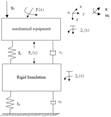
Fig. 1 shows a common single-degree-of-freedom vibration isolation system model. The model assumes that the stiffness and mass of the pedestal are infinite, and only vertical vibration is considered. In practical vibration isolation systems, factors such as the excitation force of multiple degrees of freedom, the asymmetry of the relative excitation force of the pedestal, and the multiple degrees of freedom of the pedestal will cause the vibration of the pedestal to be more than one degree of freedom, so it should be further refined. Considering the characteristics of the rigid body base, a multi-degree-of-freedom vibration isolation model is established based on an elastically supported rigid body as shown in Fig. 2.
Fig. 1The single freedom isolation system: k – elastic coefficient, c – damping
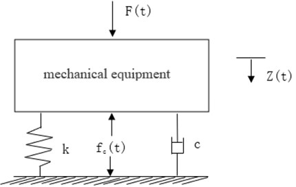
Fig. 2Multiple freedom isolation system for rigid pedestal: k1, k2 – elastic coefficient, c – damping
3. Analysis of basic vibration characteristics of active and passive vibration isolation system
3.1. Active and passive vibration system with single vibration isolator
Due to the symmetry of the vibration isolation system model this article is focused on analyzing the vibration characteristics of the pedestal, for the convenience of research, the question is analyzed in a two-dimensional plane, and only the -direction and the movement around the -axis in the coordinate system in Fig. 2 are considered and the damping characteristics of the vibration isolation system is ignored. Establishment of coordinate system based on center of surface on rigid pedestal. We assume that the excitation force transmitted to the pedestal, the vertical stiffness of the lower spring is . According to the rigid body dynamics theory, the rigid body motion can be decomposed into the superposition of translation and rotation. The dynamic equation of the base can be expressed as:
where is the moment of inertia of the base structure along the -axis direction, and is the rotation angle of the base.
When the excitation force causes the upper structure and the lower pedestal to vibrate in multiple degrees of freedom, an actuator that produces only vertical force is difficult to fully match the dynamic force transmitted to the base pedestal. For the vibration with small amplitude, the vibration of the base can be decomposed into translation in the vertical -direction and fixed-axis rotation that passes through the center of gravity and is parallel to the -axis according to Eq. (1). When acting as an actuator on the rotation axis of the pedestal, each degree of freedom does not affect each other, so the active control force can only control the vertical component transmitted to the pedestal, and the problem of incomplete control effect occurs. When the actuator is not acting on the basic rotating shaft, since the vertical driving force will produce moment action at this time, the driving force will not only control the vertical component of the excitation force but also affect the rotation component. The rotational movement of the pedestal results in different phases on the left and right sides, while the basic translation is the movement of the entire pedestal in the same phase and amplitude, which will inevitably lead to inconsistent vibration control effects at different positions on the pedestal.
Active control is added at this point assuming that the vertical active control force fc acts on , the control force will simultaneously have force and torque equal to and , then Eq. (1) will become:
where , assuming that the error measuring point and the control force are located in the same position, the error acceleration signal can be expressed as:
Let 0, the optimal control force can be obtained by simplifying Eq. (2):
At this time, the vibration acceleration at the observation point on the base is:
where is the vertical acceleration at point on the base when the optimal control force is optimal, is the corresponding rotational angle acceleration, the first is the flat vibration along the -axis, and the second is the rotational vibration caused by rotation. It can be seen that the multi-degree of freedom vibration of the base cannot be completely controlled under the action of a single point of vertical force, and still retains some flattening and rotation components.
3.2. Active and passive vibration isolation system with multiple vibration isollator
As it can be seen from the above, the reason why the base of the single bid locker isolation system is not effectively controlled by vibration consists in that the vertical control force cannot produce the right force and torque at the same time to suppress the rotating vibration, the torque generated by the single isolator is just taken into account with one factor, resulting in the situation that a part of vibration of the measuring point will rebound or even disperse at a later stage. The rigid characteristics of the base can be used to achieve the output of torque using multiple distribution actuators.
Considering that under the action of vertical excitation and torque excitation, due to the rigid characteristics of the base, vibrations transmitted to the base via the shock absorber can be equivalent to vibrations under vertical force and torque . If the number of issonators is , the vertical control force can be expressed as , and the force arms of each control force can be expressed as , then the task can be expressed as finding the solution of the system Eq. (6):
It is easy to see that for the vertical two-dimensional plane that only considers the -axis and the fundamental vibration around the -axis as shown in Fig. 2, at least two secondary sources of force are required to fully control the vibration transmitted through the vibration isolator. It can be inferred that in application at least 4 active and passive vibration isolators will be used in the vibration device for the consideration of symmetry or ease of installation.
4. Simulation example
In order to more intuitively demonstrate the vibration law of the rigid pedestal in single vibration isolation system under the control force of a single degree of freedom, the active control effect of the two-dimensional rigid pedestal model is simulated, the control system adopts the feedforward FxLMS control algorithm. The reference signal is the vibration acceleration of the vibration source, and the error signal is the acceleration measurement point on the base. The principle is shown in Fig. 3. This algorithm has been studied in detail in the literature [12]. When the convergence step size satisfies a certain condition, the convergence stability of the control algorithm can be satisfied.
The position of the actuator on the pedestal is simulated. The position of the error measurement point is the same as the control target position. Set pedestal mass 1000 kg, pedestal spring vertical stiffness 300 N/mm, rotational stiffness 300 N/rad, basic moment of inertia 500 kg∙m2, the excitation vertical force acting on the pedestal is 1000 N, and the excitation torque is 5 N∙m. So it is possible to simulate the optimal control force required when the actuator is arranged in different positions and to measure the vibration in other position measuring points after the control is stabilized.
Fig. 4 shows the optimal control force (solid line) calculated by the control system when the actuator is installed in different positions (the error measuring point follows the change of the actuator position) and the fixed position (0.1 m) when the control system is working at the vibration acceleration (dotted line). It can be seen in the figure that when the active control force is in the center (0), that is, on the rotating axis, the control force is equal to the excited vertical force, the flat weight of the vibration is completely zero, the rotation component is not affected. When the 0, with the control force position away from the shaft, the control force produces more and more torque, so the optimal control force is not simply increased or decreased, but first increased (0.039 optimal control force 1031 N) and then decreased when the 0. When the control force position is 0.1 m, that is, at the same position as the observation point, the vibration of the observation point is minimal and gradually increases as the control force position moves towards both ends.
Fig. 3Scheme of vibration control system
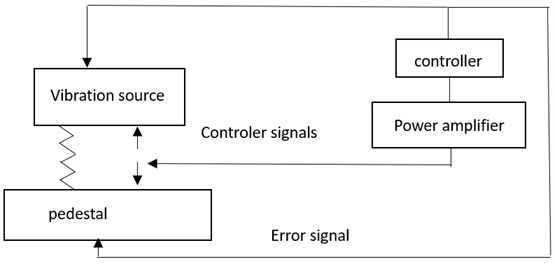
Fig. 4Optical control force and the acceleration at 0.1 m position different actuator locations
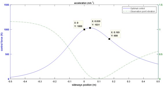
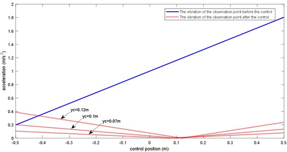
Fig. 5 shows the vibration situation of the base at different positions before and after control when the positions of the actuators are respectively 0.07 m, 0.1 m, and 0.12 m. It shows that the position of the control force (the actuator) plays an important role in the final control, which may cause the vibration of the observation point to decrease or increase, resulting in the failure to fully control the pedestal.
It can be referred from the simulation results that for the active and passive vibration isolation system with a single vibration isolator, there are two ways to fully control the vibration of the pedestal. The first is to use multi-degree-of-freedom actuators to make the control force fully match the transmitted initial excitation force. The second is to use multiple unidirectional actuators to indirectly output force and torque to control the base directly. Limited by the hardware resources of hardware conditions. In this paper, only single-degree-of-freedom actuators are used to build active and passive vibration isolation systems with single isolator and multiple isolators for experimental verification.
Fig. 5Acceleration of different position when the actuator is located at 0.07 m, 0.1 m, 0.12 m
5. Test verification
A single vibration isolator active and passive vibration isolation test platform shall be built as shown in Fig. 5. In the test, having a size of 1 m×1 m×0.23 m and weighing about 1t, the entire lower pedestal has a first-order elastic mode frequency of 564 Hz, which is far beyond the one in our research. With 4 airbags elastically supported, an electromagnetic airbag vibration isolator (containing an actuator capable of generating control force) is installed in the middle of the pedestal, and the upper mass fixed at it weighs about 100 Kg, which is excited by the inertial actuator to generate initial vibration .Acceleration sensors shall be installed at the lower surface of the pedestal at the position corresponding to the vibration isolator as the error sensor of the active control algorithm. On the upper surface of the pedestal, 16 additional acceleration sensors as shown in Fig. 6 are arranged uniformly (from top to bottom, from left to right). No. 1-16) to operate as observation sensors to evaluate the overall vibration isolation effect.
Fig. 6Experiment device using single isolator: 1 – upper mass block; 2 – shock absorber; 3 – lower base; 4 – Support spring
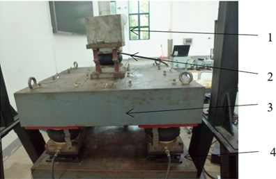
Fig. 8 contains curves of the recorded 60 s vibration data from 16 observation points during the control process. The active control is turned on at 17 s. It can be seen that the vibrations at the measuring points 1-4 are gradually converging and decreasing, while the measuring points 13-16 show obvious vibration attenuation first and then rebound the increase phenomenon, but overall, there is still a large vibration attenuation, which is consistent with the results of theoretical analysis.
Fig. 7Location of 16 observation points
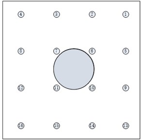
Fig. 8Control process of 16 observation points
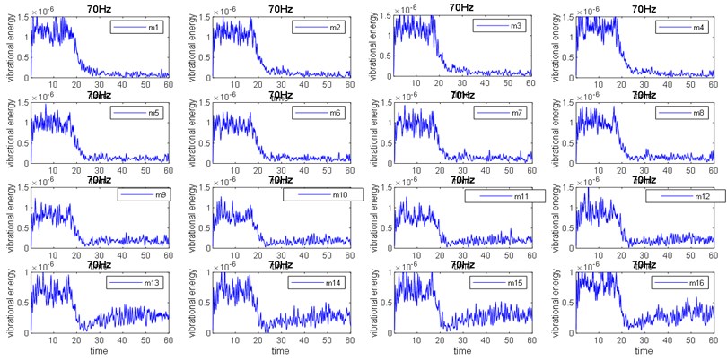
Fig. 9Control process of 16 observation points at 60 Hz
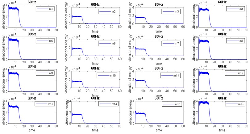
Fig. 10Control process of 16 observation points at 80 Hz
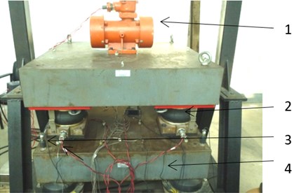
The single-vibration isolator test bench was modified. Four rubber vibration isolators were used to support the rigid pedestal, and four active vibration isolators (all of them with actuators) were used to connect the superstructure and the pedestal, Because the upper mass block is heavier, a vibration motor is used as the excitation source to conduct an experimental study on the vibration isolation system supported by multiple vibration isolators. Four acceleration sensors are arranged next to the four vibration isolators as error sensors, and 16 acceleration sensors are evenly arranged at the lower surface of the pedestal to observe and evaluate the vibration isolation effect. The test device is shown in Fig. 11.
Fig. 11Experiment device with 4 active-passive isolators: 1 – vibration motor; 2 – active and passive vibration isolation; 3 – error measurement point; 4 – lower base
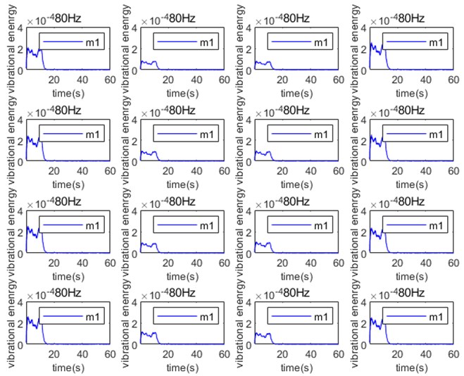
After installing the vibration motor, the inverter is used to adjust the motor speed so as to stimulate the vibration signal to carry out the active vibration isolation test. Fig. 9 and Fig. 10 show the vibration process of 16 error measuring points at 60 Hz and 80 Hz excitation, each measure points shows a small vibration magnitude of 8 points (2, 3, 6, 7, 10, 11, 14, 15) in the middle before control, with 8 points on both sides (1, 5, 9, 13, 4, 8, 12, 16) with vibration magnitude characteristics, indicating that the basic vibration contains rotating components, After opening each measuring point, the active control showed a consistent control effect, with an average value of up to 40 dB. Experiments show that observe points at all frequencies can be well controlled, and there is no local increase or excessive control, so the conclusion that the structural vibration analysis of the rigid body base with elastic support can be fully controlled is verified.
6. Conclusions
In this paper, the vibration transfer characteristics of the electromagnetic airbag active and passive vibration isolation system based on the rigid body base are studied. Based on the electromagnetic actuator that can only output a single degree of freedom force, the active and passive vibration isolation of a single vibration isolator and multiple vibration isolators are analyzed. Vibration characteristics of the base of the rigid body structure in the system. According to the theory of rigid body dynamics, the multi-degree-of-freedom vibration of the base is decomposed into two mutually orthogonal components, translational and fixed-axis rotation. Control the vibration in the translation direction, and the unreasonable placement of the actuator will lead to adverse effects such as mis-control or over-control. Additionally, global control of base vibration can be achieved by arranging multiple actuators simultaneously. Finally, test benches for single isolator and multi-isolator vibration isolation systems were built to verify the above conclusions.
References
-
Lueg P., “Process of silencing sound oscillations,” German patent DPR No. 655508, 1933.
-
Y. P. Xiong, Research on Vibration Power Flow and Active and Passive Control of Flexible Coupling System. Beijing: Aviation Industry Press, 1999.
-
J. C. Niu and Y. Y. Liu, “Optimal control strategy of power flow in active vibration isolation system,” Noise and Vibration Control, Vol. 5, pp. 2–5, 2000.
-
P. Gardonio, S. J. Elliott, and R. J. Pinnington, “Active isolation of structural vibration on a multiple-degree-of-freedom system, part I: the dynamics of the system,” Journal of Sound and Vibration, Vol. 207, No. 1, pp. 61–93, Oct. 1997, https://doi.org/10.1006/jsvi.1997.1152
-
R. A. Smith and G. B. B. Chaplin, “The implications of synchronised cancellation for vibration,” Proceedings of Inter-Noise, pp. 403–406, 1983.
-
C. Howard, “Active isolation of machinery vibration from flexible structures,” University of Adelaide, 1999.
-
K. Zhen, J. M. Qiu, Y. P. Wang, and Y. Yang, “Structural design and experiment of inertial multi-degree of freedom piezo actuator,” Micro Motor, Vol. 49, No. 2, pp. 15–20, 2021.
-
Wang Chunyu, Li Yan, and Shuai Changgeng, “Error-sensor location scheme in active vibration isolation based on SDOF actuator,” Journal of Vibration and Shock, Vol. 39, No. 22, pp. 254–260, 2020.
-
C.-Y. Wang, L. He, Y. Li, and C.-G. Shuai, “A multi-reference filtered-x-Newton narrowband algorithm for active isolation of vibration and experimental investigations,” Mechanical Systems and Signal Processing, Vol. 98, pp. 108–123, Jan. 2018, https://doi.org/10.1016/j.ymssp.2017.04.044
-
Y. F. Guan, “Dynamic analysis of flexible basic multi-support nonlinear vibration isolation system,” Shandong University, 2013.
-
N. Zhang, L. He, and Y. Li, “Analysis of the influence of base stiffness on the control effect of active and passive vibration isolation systems,” Noise and Vibration Control, Vol. 37, No. 3, pp. 62–65, 2017, https://doi.org/10.3969/j.issn.1006-1355.2017.03.012
-
Y. Li, L. He, C.-G. Shuai, and F. Wang, “Time-domain filtered-x-Newton narrowband algorithms for active isolation of frequency-fluctuating vibration,” Journal of Sound and Vibration, Vol. 367, pp. 1–21, Apr. 2016, https://doi.org/10.1016/j.jsv.2015.12.019
About this article

The paper is funded by the fund projects: Project to promote young talents in military science and technology (18-JCJQ-QT-002).
