Abstract
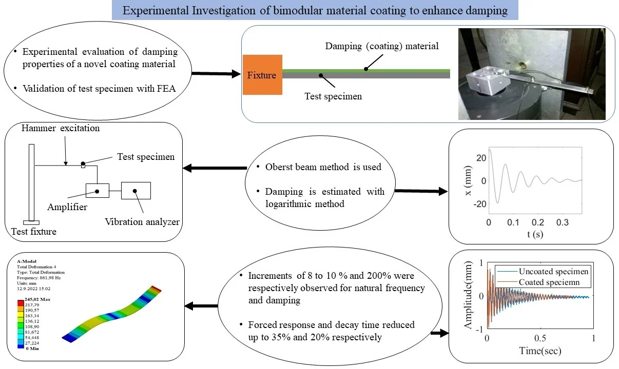
Hard coatings can be used to increase damping when applied on the surface of the components of turbomachinery. This can be effective to reduce the resonant vibration level of components working in a high cycle fatigue environment due to the extremely high operational speed. This paper discusses the experimental investigation of a bi-modular material hard coating to enhance damping in structural steel elements. Firstly, a hard coating (Al2O3+MgO) is applied on AISI 304L stainless steel substrate by plasma spraying. After that, a layer of chrome is deposited by chrome plating. Dynamic responses of both coated and uncoated samples are measured. The damping ratio of the test specimen is extracted from the time response by the logarithmic decrement method. Improved damping capacity of the coated steel sample is observed and is mainly attributed to the thin coating of chrome on the steel structure. The natural frequency of coated specimen showed 8 to 10 % improvement, the forced response showed a 30 to 35 % decrement in displacement, the damping ratio showed a 200 % increment, and the time of decaying showed a 20 % decrement. The results of the present study provide new ideas for the development of high-damping structural elements.
Highlights
- Experimental investigation of a bi-modular material hard coating to enhance damping in structural steel elements.
- Applying hard coating on AISI 304L stainless steel by plasma spraying and after that deposition of a layer of chrome on it by chrome plating.
- Measurement of dynamic response of both coated and uncoated samples and validation of results with FEA.
- Improvement in damping capacity of the coated steel samples mainly due to thin coating of chrome on the steel.
1. Introduction
Suppression of vibration in turbomachinery is very crucial to minimize damages because of high cycle load build-up due to working in a high cycle fatigue environment. It diminishes the performance and lifetime of the system. On the other hand, structures with improved damping capacity can dissipate mechanical energy under external stresses. Hence it is essential to understand how to improve the damping capacity of the materials used in developing mechanical systems as it plays a pivotal role in the structural behavior against harmful vibrations. In turbomachinery, aerodynamic and structural damping sources are applied for performance improvement. Aerodynamic damping mainly comprises fluid-structure interaction when the flow passes by the blades of turbomachinery. While aerodynamic damping is sometimes used in the industry, the drawback is that the damping ratio can be negative in some specific cases, like at the nodal diameter. At that point, structural damping plays important role in the stability of the whole system because structural damping always remains positive, and it also reduces the vibration amplitude of the rotating blades. Thus, there is a need to find alternative means to suppress harmful vibrations in industrial applications. In electrical machines, for example, the use of layered sheet steel is being explored as a possible approach to damp vibrations and at the same time maintain a reasonable overall structural mass [1, 2]. While the use of layered sheet steel looks promising from the modal response perspective, its application is not desired in for example the blades of steam turbines. In this work, the use of bi-modular coating material on structural steel plates is explored as a possible means to improve the damping characteristics of the blades used in industrial applications.
Many have focused on using hard coating materials to produce improved damping characteristics in industrial machines [3-9]. Sun [3] investigated the effect of hard coating material (Aluminum oxide) on the structural damping of compressor blades. Experimental Modal analysis and FEM were used to check the effect of hard coating on damping improvement. Both methods showed the damping improvement by the application of hard coating. Liming Yu et al. [4] discussed the Reuss model and Hashin–Shtrickman equation to evaluate the damping efficiency of hard coating structure. The results show that there is the optimum thickness of a layer of coating at which the coating structure has maximum strength and damping capacity. Ivancic et al. [5] compared hard coatings with different thicknesses using sine sweep and dynamic ping test. The results indicate improved damping capability. Liu et al [6] determined the modulus of elasticity and Poisson’s ratio for a hard coating by destructive and non-destructive methods to find out the optimum parameters for improvement in damping. Reed et al. [7] investigated the non-linear, strain-dependent nature of stiffness and damping properties of hard coatings. Yu and Ma [8] investigated the role of micro-slip at the interface of a metal and ceramic coating for the improvement of the damping capacity of hard coating. Syed et al. [9] investigated the effect of substrate material thickness on damping treatments by comparing constrained layer and free layer damping.
Sun et al. [10] compared damping improvements by using hard coating and epoxy material coating. Enhancement in vibration damping is observed in both cases but hard coating material (alumina) showed more improvement in damping. Amadori et al. [11] compared the damping properties of hard coating made by an anodizing process and by a reactive plasma vapor deposition process. Hard-coated specimens showed improvement in damping compared to un-coated specimens. Gao et al. [12] studied the effect of an optimized method by applying hard coating on both sides of blades to improve the performance of integrally bladed disks under severe working conditions. The harmonic response of integrally bladed disk with hard-coated blades is measured by relative damping to achieve its damping matrix. Patsias et al. [13] discussed the role of hard coating materials in damping improvement at room and elevated temperatures. The damping and modulus of elasticity of hard coatings were obtained from the decay curve of the coated specimens. Blackwella [14] investigated the effect of Hard Coating material (MgO+Al2O3) on the damping properties of titanium blades. Air plasma spraying was used as a coating method due to its low cost, and provision of stronger, and denser coating. Plate dimensions replicating actual turbine blades were used to perform experiments. Mode shapes were used to characterize the damping of plates. The experiments showed an increase in damping up to an effective level.
Casadei et al. [15] analyzed the vibration damping properties of thermal barrier coating containing the thin layer of ductile material incorporated in the elastic hard coating. For the analysis of required properties, a ceramic matrix (YSZ) inserted with thin layers of Platinum was developed. The methodology showed improvement in damping although more focus was on creep prevention. Movchan et al. [16] studied the hard coating material (Sn-Cr-MgO) system having high damping properties. In Sn-Cr-MgO coating, tin is used as a highly ductile material while MgO is used as a hard material. In a complete coating model, hard material is preferable as the top coating layer while ductile material is helpful in the layers close to the substrate. High damping capability and high hardness of the hard coating and ductile material played a significant role in the improvement of the lifetime of gas turbine compressor blades. Electron beam physical vapor deposition (EBPVD) was used as a coating method. However, EBPVD has certain limitations in cost, time of material deposition, and adhesion of coating material to the substrate.
In this study experimental investigation of a novel bi-modular material coating is performed to check the effect of this coating on the damping enhancement of AISI 304L stainless steel test specimen. The bi-modular material coating is the combination of hard coating (MgO+Al2O3) and a thin layer of chrome coating. In the first step sandblasting of test specimen was performed to improve the adhesion of coating to the surface of test specimen and then bond coat (NiCrAlY) was applied to enhance the stability of coating. Hard coating was applied on AISI 304L stainless steel substrate by plasma spraying method in the next phase and at the end a thin layer of chrome was deposited by chrome plating to complete the process. Hard coating structures have vacant interstitial spaces, the idea was to incorporate the small-sized chrome atom into these spaces and to check the effect of this novel bi-modular coating on the improvement of damping. Consequently, the main objective of this work is to determine experimentally the dynamic properties of the bi-modular material coating in terms of its capability to improve structural damping in steel plates. Experimentally measured values of dynamic properties are validated by analytical calculations and numerical simulation of the test specimen.
2. Experimental study
Fig. 1 shows a test specimen of AISI 304L stainless steel. The Oberst beam method (OBM) described in the ASTM E-756 [17] standard was followed to measure the vibration damping properties of the example test specimen. The OBM is a classical method based on a multilayer cantilever beam that comprises the base beam and one or two layers of other materials. The base beam is usually made of lightly damped materials like steel and Aluminum. An accurate measurement methodology is required to use the Oberst beam method. It is a standard experimental technique used for measuring elastic and damping properties of the material as a function of frequency and is typically a useful approach for materials e.g., metals, enamels, ceramics, wood, etc. In the present work, the OBM method is used to experimentally investigate the bi-modular material coatings to enhance damping. An optical microscope is used to measure the thickness of the bi-modular coating. The thickness of the bi-modular coating is found to be in the range of 230-240 µm. The thickness of the hard coating is in the range of 140-150 µm while chrome thickness is in the range of 80-90 µm.
2.1. Preparation of test specimens
The test specimen was prepared according to standard ASTM E-756 for damping measurement. The dimensions of the test specimen shown in Fig. 1 are given in Table 1. AISI-304L was selected as the substrate material as it is the most versatile and widely used type of stainless steel. It also has high corrosion resistance and can also be very effective in elevated temperatures as well as in cryogenic temperatures [18]. Sandblasting of the test specimen was performed to make the surface rough and increase adherence to the coating. Also, a bond coat (NiCrAlY) was applied to the surface of the test specimen to ensure better adhesion between the bi-modular coating and the steel specimen. The bond coat is usually applied for thermal barrier coatings to increase their life and stability. So, the adherence performance and stability of the coating were ensured by sandblasting and bond coat. The economical aspect of this investigation is not considered as it was performed at a lab scale, but all the materials used in the investigation are common and easily available in the market. AISI 304L is commonly used in the industry while Alumina and chrome can also be arranged easily and the application of Bi-modular coating in turbomachinery components at an industrial scale will further reduce the manufacturing cost. The hard coating was developed by mixing 72 % of Al2O3 and 28 % of MgO [14]. After that, a layer of chrome is deposited on the specimen. Due to properties like hardness and corrosion resistance, chromium is chosen as a layer element above hard coating to develop bi- modular coating.
Fig. 1Damping measurement specimen
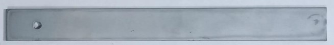
Table 1Physical and mechanical properties of test specimen
Length (mm) | Width (mm) | Thickness of the specimen (mm) | Thickness of coating (mm) | Material density of test specimen (kg/m3) | Young’s modulus of test specimen (N/m2) | Material density of coating (kg/m3) | Young’s modulus of coating (N/m2) |
202 | 20 | 2 | 0.240 | 7850 | 1.97×10¹¹ | 3490 | 3.15×10¹¹ |
2.2. Experimental setup
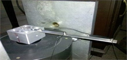
Fig. 2 shows the test setup developed to study the response of the bi-modular coating on the test specimen to enhance damping capacity. Here, the natural frequency, resonant frequency, and time response are the main output of the test setup. These would allow the extraction of the complete dynamic properties of the test specimen. The complete setup consists of the test specimen, holding fixture, accelerometer Bruel & Kjaer (B&K-4384), Vibration amplifier (B&K-2525), and Vibration analyzer (SD-380). Vibration analyzer is used to measure the vibration of the test specimen in terms of acceleration, displacement, and velocity. In this experiment amplifier, B&K-2525 is used to amplify and provide vibration signals from the accelerometer to the vibration analyzer. This charge amplifier can be used for a frequency range from 1 Hz to 30 kHz. An accelerometer was used to measure vibration in the form of acceleration, which was then converted into velocity or displacement. Its sensitivity is 1.51pc/g, frequency range 1 Hz to 26 kHz, measuring range up to 5000 g and temperature range – 74 °C to 250 °C. Forced response was measured by the experimental setup as shown in Fig. 3. The mounting position of accelerometers at the different positions of the test specimen is shown in Fig. 3.
Fig. 2The layout of the experimental setup
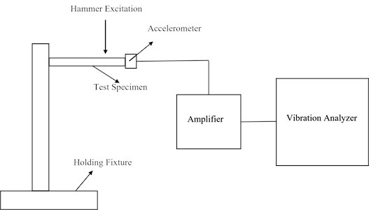
Fig. 3Mounting position of sensors
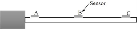
Test specimens were held by a holding fixture in a cantilever beam position as shown in Fig. 3. The surface of the test specimens was cleaned to ensure the adherence of the accelerometer to the surface with the help of glue. Excitation was induced in the test specimen with the help of a manual hammer. Excitation was made at the end of the test specimen to excite the vibration modes up to a frequency of 1500 Hz. The accelerometer (B&K-4384) was connected to a vibration amplifier (B&K-2525). After specimen excitation with the manual hammer, the accelerometer sends its vibration to the amplifier for the amplification of the signal. The amplifier, which is connected to a vibration analyzer (SD-380), receives the vibration signal and analyzes it according to the requirement in the time or frequency domain. Frequency response and time response were recorded in this experiment to measure the natural frequencies of test specimens, damping ratios, and time of decaying of the response. To measure the forced response three accelerometers were attached to the specimen and forced excitation in the range of 100 Hz for 1st mode and 300 Hz for 2nd mode were given to the test specimen by vibration exciter (B&K-4808) and excitation was controlled by vibration exciter control (B&K-1050). The operating frequency range of the vibration exciter is 1 Hz to 10 kHz. Acceleration obtained from accelerometers is then integrated to get displacements to draw mode shapes. The vibration data obtained from the vibration analyzer is processed locally with the help of Matlab Code for further analysis.
2.3. Damping estimation
There are many methods to estimate damping parameters from experimental data or model based on frequency domain and time domain signals. In dynamics analysis, five methods are commonly used to find out damping from experimental data: the half power bandwidth method, logarithmic decrement (decay rate) method, a random decrement technique, Curve fitting and stochastic subspace identification method [21]. To investigate the damping enhancement by the application of bi-modular material coatings, parameters like frequency response, damping ratio, and time of decaying of measured response play a vital role [2]. In this study, the Logarithmic decrement method is used among five methods mentioned above due to its suitability to estimate damping parameters because damping cannot be measured directly. The logarithmic decrement method is among the most popular time-response method to measure damping. It elaborates on the rate the amplitude of a free damped vibration diminishes. It is the logarithm of the ratio of any of two successive amplitudes.
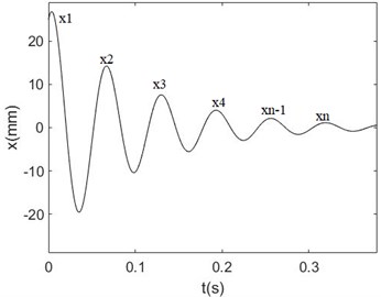
When a single degree of freedom system is excited by an initial condition excitation its response takes the form of time decay as shown in Fig. 4 and Eq (1). Here, successive amplitudes of the time response of coated and uncoated specimens were taken to find out the damping ratio.
Fig. 4Time response used to measure damping
Response of damped free vibration can be shown as:
in which damped natural frequency is given by:
If the response at the time is denoted by and the response at is denoted by then from the above equation, we have:
Replacing the value of in Eq: (3) from Eq: (2):
The logarithmic decrement can be given as:
where is the decrement, is the number of successive peaks, is the measured displacement response. Solving Eq. (5) yields the expression for damping ratio:
Further solving results in:
3. Results and analysis
Experimental modal analysis was used to check the dynamic properties of the test specimen. Dynamic properties of the test specimen were measured before and after coating to understand the effect of bi-modular material coating on the improvement of the damping. The natural frequencies were used as an indicator in experimental modal analysis to check the effect of coating on the enhancement of damping. Natural frequencies of coated and uncoated test beams were measured for the first three bending modes. These measurements were attained using the experimental setup described above in Fig. 2. Results of natural frequencies of un-coated and bi-modular coated (hard coated +chrome coated) samples in the frequency range of 0 to 1500 Hz for first three bending modes are shown in Fig. 5 and Fig. 6. Here, it is evident that coated test specimen is showing more damping as compared to uncoated specimen. Adding a layer of coating material has helped to slightly increase the natural frequency, also the peak of the 4th natural frequency is seen to have disappeared as shown in Fig. 6.
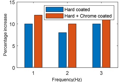
The effect of deposition of each layer of coating material (first hard coating and then hard +chrome coating) on the natural frequency of the test beam is elaborated in detail in Table 2. The natural frequencies in Table 2 are averages of three separate vibration testing routines to improve the accuracy of results. It is evident from Table 2 that addition of bi-modular coating (mag spinel +chrome coating) has an incremental effect on the natural frequency with very little difference across the specimens. The percentage increase in natural frequency for 1st, 2nd, and 3rd mode by the application of hard coating and bi-modular coating (hard +chrome coating) is illustrated in Fig. 7.
Fig. 5Frequency response plot for uncoated beam
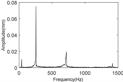
Fig. 6Frequency response plot of coated beam
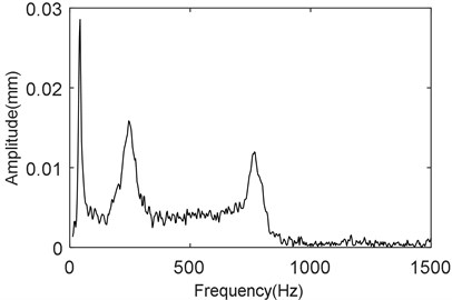
Table 2Comparison of natural frequency of uncoated, hard coated and bi-modular coated specimen
Mode | Analytical values (Hz) | FEA values (Hz) | Uncoated (Hz) | Al2O3+MgO coated (Hz) | (Al2O3+MgO) + chrome coated (Hz) | FEA Values of coated specimen (Hz) |
1st | 39.73 | 39.86 | 40 | 44 | 47 | 49.18 |
2nd | 249 | 249.7 | 258 | 278 | 293 | 308 |
3rd | 702.9 | 698.9 | 710 | 780 | 805 | 862 |
Fig. 7Percentage increase in frequency
The experimental values of the natural frequencies can be compared with analytical values and values calculated by FEA.
The analytical calculation of the natural frequency is given as:
The first, second, and third natural frequencies of a cantilever beam with a fixed end at one side can be calculated by the following formulas [20]:
By substituting the properties of the measured test specimen given in Table 1 into the Eqs. (9-11) the first, second, and third natural frequencies become 39.73 Hz, 249 Hz, and 702.79 Hz. By comparing with the experimental values of the cantilever beam it is concluded that analytical values are quite close to the experimental values. The difference for the first frequency is 0.67 %, for 2nd frequency is 3.48 % and 3rd frequency is 1.01 % respectively.
The modelling of the uncoated test specimen to find out the natural frequencies by FEA and FEA mesh details are shown in Figs. 8-11 and Table 3. The results for natural frequency calculated by numerical simulation software Ansys are showing that there is a difference of 0.35 % for the 1st natural frequency, 3.21 % for the 2nd natural frequency, and 1.56 % for the 3rd natural frequency as compared to experimental values.
Table 3FEA mesh details of uncoated specimen
Element type | Element size (mm) | No. of elements | No. of nodes | Mesh sizing resolution |
SHELL181 | 1 | 8080 | 46221 | 5 |
Table 4FEA mesh details of coated Specimen
Element type | Element size (mm) | No. of elements | No. of nodes | Mesh sizing resolution |
SHELL181 | 1 | 12120 | 75614 | 5 |
Fig. 8FEA mesh of uncoated specimen
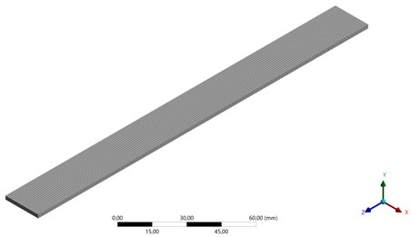
Fig. 91st Natural frequency (39.86 Hz)
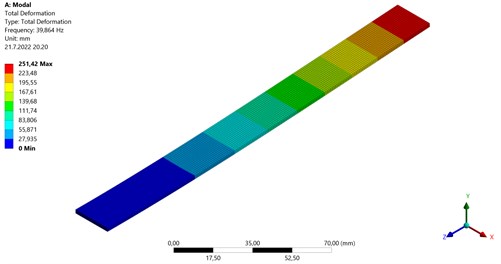
Fig. 102nd Natural frequency (249.7 Hz)
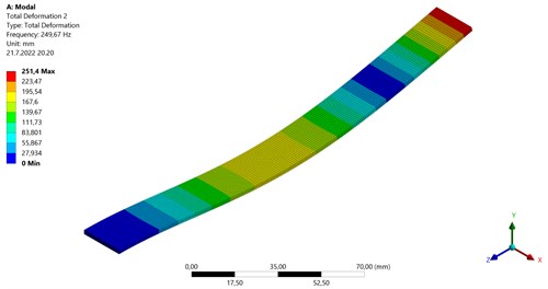
Fig. 113rd Natural frequency (698.9 Hz)
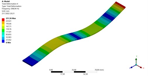
Fig. 12FEA mesh of coated specimen
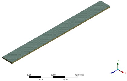
Fig. 131st Natural frequency (49.18 Hz)
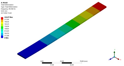
Fig. 142nd Natural frequency (308 Hz)
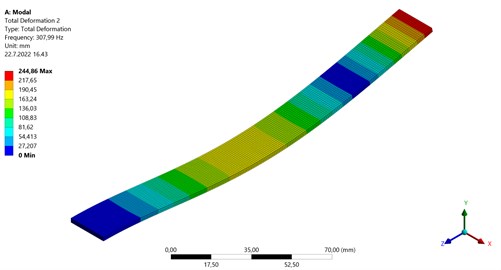
Fig. 153rd Natural frequency (862 Hz)

The FEA analysis and FEA mesh of bi-modular material coated sample is shown in Figs. 12-15 and properties of coating [22] are described in Table 1. The mesh properties of coated sample are shown in Table 4. The coated specimen is modelled as multilayer with 2 mm thick substrate and 0.24 mm coating layer. The results for natural frequency calculated by numerical simulation software Ansys are showing that there is difference of 4.63 % for the 1st natural frequency, 5.11 % for the 2nd natural frequency and 7.08 % for the 3rd natural frequency as compared to experimental values.
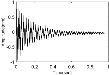
The damping ratios were calculated by the Logarithmic decrement method according to Eq. (6). Like the approach illustrated in Fig. 4 damping ratio is extracted based on successive amplitudes of the measured response. The damping ratio was extracted for the uncoated and coated beam for a frequency range of 0 to 500 Hz and when the analyzer was set in time-domain mode. The vibration decay of the un-coated and bi-modular coated (hard +chrome coated) beam is shown in Fig. 16 and Fig. 17. In Fig. 16 the response of the uncoated beam decay with time is shown.
A ratio of these successive amplitudes was used in logarithmic decrement method to calculate the damping ratio which is 0.008 as shown in Table 5.
Fig. 16The response of uncoated specimen
From Fig. 17 the damping ratio of the bi-modular coated specimen is seen to increase as the amplitude of vibration decay is dampened by the layer of bi-modular coated deposited on it. The amplitude of vibration decay has its first peak at 0.5 mm, and it is decreasing till the complete decay. The damping ratio, in this case, is found to have an average value of 0.0235. Table 5 and Fig. 18 shows that the average damping ratio is improved as it is increasing from 0.008 to 0.0165 for the case with the addition of hard coating (mag spinel coating) which is almost 200 % compared to the uncoated specimen and for hard +chrome coating (bi-modular coating) it is increasing from 0.0080 to 0.0235 which is almost 293 % compared to the uncoated specimen. The average damping ratio is shown in Table 5 which is the result of separate vibration testing routines conducted to improve the accuracy of the estimation.
Fig. 17The response of coated specimen
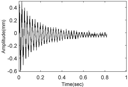
Table 5Damping ratio comparison
Coating type | Uncoated | Al2O3+MgO coated | (Al2O3+MgO) + Chrome coated |
Average damping ratio | 0.0080 | 0.0165 | 0.0235 |
Percentage increase | 206 | 293 |
Forced response measurement is a very important part of this study because it allows an understanding of the behavior of the test specimen under time-varying loading. The test beam was excited in the range of 1st and 2nd natural frequency by a vibration shaker. The response was measured in terms of vibration acceleration and converted to vibration displacement. The test beam length is then plotted against these displacements to get the forced response values. A means of visualizing the points of maximum displacement at resonance and helping to draw the mode shapes. As mode shape is the physical reaction (change of shape) of any structure at resonance.
The first three bending frequencies of the test specimen for the coated and uncoated case are measured and forced response (mode shapes) for the first two bending frequencies are shown in Fig. 19 and Fig. 20 and values of displacements along the length of the beam with and without coating are described in Table 6 and Table 7. From Fig. 19 it is visible that in the case of 1st resonant frequency, the response of the uncoated beam is high and is in the range of 0.13 mm while with the addition of hard coating it shows decrement up to 0.1 mm, and adding bi-modular material coating further limits the amplitude up to 0.06 mm. The response of the beam is decreasing gradually with the addition of each layer of coating material.
Fig. 18Damping ratio comparison
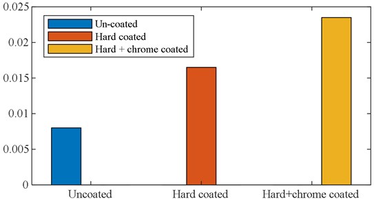
Fig. 19Response of beam for at 1st natural frequency
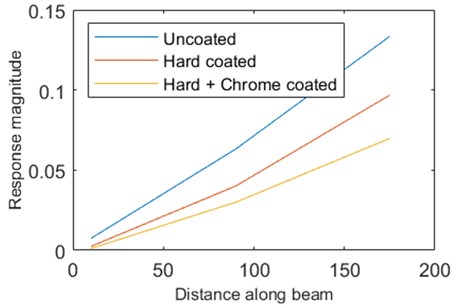
Fig. 20 describes the effect of coating on the forced response in the case of 2nd resonant frequency. The response of the uncoated beam is in the range of 0 to 18 mm while after the deposition of coating it reduces to 13 mm and 10 mm respectively for hard coating and bi-modular material coating. This dictates that, by adding a layer of bi-modular material coating, the forced response of the beam will decrease, which is an indication of improvement in damping. Table 6 and Table 7 show the response of the test beam at 1st and 2nd resonant frequencies for uncoated and bi-modular material-coated beams at all three positions of the sensors. The results indicate that the decrease of forced response is in the range of 30 to 35 % at 1st and 2nd natural frequencies.
Time consumed in the complete decay of vibration energy is another parameter in modal analysis which is very useful to predict the damping properties of a material. The decay time is calculated from the time domain response of the test specimen. The decay time of uncoated and bi-modular material-coated specimens is shown in the same Fig. 21. As illustrated in Fig. 21 the uncoated specimen has more amplitude of vibration and the time consumed during the complete decay of vibration energy is close to 1 sec. The response of bi-modular material coated beam, on the other hand, shows a rather slightly decreasing amplitude of vibration, and the time consumed in complete decay of vibration energy is about 0.8 sec. Although at the start of the response, the amplitude of coated beam is slightly higher than the uncoated beam, it is evident from the response shown in Fig. 21 that, the amplitude keeps decreasing, and eventually, the vibration energy decays well before the uncoated beam. Hence the deposition of coating material increased the dissipation of the vibrational energy of the coated specimen and as a result, the response of the coated specimen decays in a short time.
Fig. 20Response of beam at 2nd natural frequency
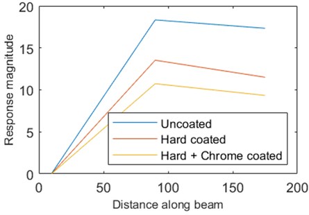
Fig. 21The time of decaying of the uncoated beam and coated beam
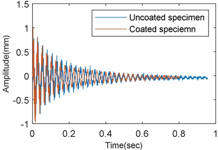
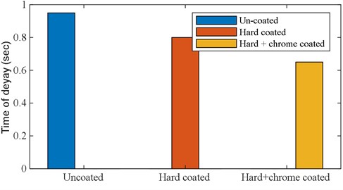
Table 8 shows the percentage decrease in time of vibration decay of uncoated, hard-coated (mag spinel coating), and hard-coated +chrome coated specimens (bi-modular material coating). This estimate of time of decay shown in Table 8 is the result of an average of three separate vibration testing routines that were conducted to improve the accuracy of the measurement. It shows that time of decay of vibration energy is decreasing 16 % in the case of hard coating and 30 % in the case of the bi-modular material coating compared to uncoated beam.
Table 6Response of beam at 1st natural frequency
Sensor | Uncoated displacement (mm) | (Al2O3+MgO) coating displacement (mm) | (Al2O3+MgO) + Chrome coating displacement (mm) |
A | 0.00744 | 0.00244 | 0.00113 |
B | 0.06321 | 0.040123 | 0.03001 |
C | 0.13345 | 0.096785 | 0.0698 |
Table 7Response of beam at 2nd natural frequency
Sensor | Uncoated displacement (mm) | (Al2O3+MgO) coating displacement (mm) | (Al2O3+MgO) + chrome coating displacement (mm) |
A | 0.076345 | 0.04123 | 0.02543 |
B | 18.334 | 13.531 | 10.734 |
C | 17.334 | 11.503 | 9.336 |
Table 8Comparison of time of decaying
Coating type | Uncoated | Al2O3+MgO coated | (Al2O3+MgO) + Chrome coated |
Time of Decaying(sec) | 0.95 | 0.8 | 0.65 |
Percentage decrease | – | 16 | 30 |
Fig. 22 shows the comparison of time of decaying of vibration energy of uncoated, hard-coated, and bi-modular coated beams. Overall, it is evident that the addition of coating material has a significant effect on decreasing the time consumed in decaying vibration energy and consequently enhancing the damping of the test beam compared to the uncoated beam.
Fig. 22Decrease in decaying time
4. Conclusions
The Oberst beam method (OBM) is used to investigate the damping properties of the bi-modular (Al2O3+MgO+Chrome) material. The main purpose of the research is to check the effect of bi-modular material coating on the improvement of damping properties of rotating machinery. The method used is shown to be effective in measuring and comparing the damping properties of material before and after the coating.
This paper demonstrates that a bi-modular material coating is effective in improving the damping properties of steel structures. Dynamic properties of the uncoated beams were measured at the initial stage for comparison. A bond coat is applied to the test specimen for proper adhesion. Hard coating is then applied to the test specimen and dynamic properties were again checked. After that, a thin layer of chrome is applied to the hard coating to form a bi-modular coating. Dynamic properties of the bi-modular coating were finally checked for comparison and analysis. The outcome of the research is encouraging as it indicates improved damping parameters. The following are some important parameters that showed significant improvement.
1) Natural frequencies of test samples with coating showed an 8 to 10 % increment in natural frequency.
2) 200 % increment is observed in the damping ratio.
3) The forced response showed that there is a 30 to 35 % decrement in the magnitude of response.
4) Decaying time of vibration with the coating is reduced up to 20 %.
The presented experimental modal analysis technique provides an effective way of determining the damping characteristics of structural steel. The work presented in the paper will help designers and engineers accurately estimate the structural damping while trying to increase resistance to unwanted vibrations and improve the overall reliability of the system.
References
-
R. S. Semken, C. Nutakor, A. Mikkola, and Y. Alexandrova, “Lightweight stator structure for a large diameter direct‐drive permanent magnet synchronous generator intended for wind turbines,” IET Renewable Power Generation, Vol. 9, No. 7, pp. 711–719, Sep. 2015, https://doi.org/10.1049/iet-rpg.2014.0391
-
C. Nutakor, R. S. Semken, J. E. Heikkinen, J. Sopanen, and A. Mikkola, “Layered sheet-steel damping estimation using optical vibrometry,” in ASME 2015 International Design Engineering Technical Conferences and Computers and Information in Engineering Conference, Aug. 2015, https://doi.org/10.1115/detc2015-46867
-
J. Sun, “Vibration characteristics and structural damping of rotating compressor blades,” Ph.D. Thesis, Stockholm, 2015.
-
L. Yu, Y. Ma, C. Zhou, and H. Xu, “Damping efficiency of the coating structure,” International Journal of Solids and Structures, Vol. 42, No. 11-12, pp. 3045–3058, Jun. 2005, https://doi.org/10.1016/j.ijsolstr.2004.10.033
-
F. Ivancic and A. Palazotto, “Experimental considerations for determining the damping coefficients of hard coatings,” Journal of Aerospace Engineering, Vol. 18, No. 1, pp. 8–17, Jan. 2005, https://doi.org/10.1061/(asce)0893-1321(2005)18:1(8)
-
S. Liu and Q. J. Wang, “Determination of Young’s modulus and Poisson’s ratio for coatings,” Surface and Coatings Technology, Vol. 201, No. 14, pp. 6470–6477, Apr. 2007, https://doi.org/10.1016/j.surfcoat.2006.12.021
-
S. A. Reed, A. N. Palazotto, and W. P. Baker, “An experimental technique for the evaluation of strain dependent material properties of hard coatings,” Shock and Vibration, Vol. 15, No. 6, pp. 697–712, 2008, https://doi.org/10.1155/2008/853689
-
L. M. Yu and Y. Ma, “An interfacial damping model for hard coating structure,” Advanced Materials Research, Vol. 314-316, pp. 191–96, Aug. 2011, https://doi.org/10.4028/www.scientific.net/amr.314-316
-
Rizwan Ul, Haq Syed, M. Sabir, Jiang Wei, and D. Shi, “Effect of viscoelastic material thickness of damping treatment behavior on gearbox,” Research Journal of Applied Sciences, Engineering and Technology, Vol. 4, No. 17, pp. 3130–3136, 2012.
-
J. Sun and L. Kari, “Coating methods to increase material damping of compressor blades: measurements and modeling,” ASME Turbo Expo 2010: Power for Land, Sea, and Air, Oct. 2010, https://doi.org/10.1115/gt2010-23790
-
S. Amadori, G. Catania, and A. Casagrande, “Experimental evaluation and modeling of the damping properties of multi-layer coated composites,” in Coatings, Vol. 8, No. 2, p. 53, Jan. 2018, https://doi.org/10.3390/coatings8020053
-
F. Gao and W. Sun, “Vibration characteristics and damping analysis of the blisk-deposited hard coating using the Rayleigh-Ritz method,” Coatings, Vol. 7, No. 8, p. 108, Jul. 2017, https://doi.org/10.3390/coatings7080108
-
S. Patsias, C. Saxton, and M. Shipton, “Hard damping coatings: an experimental procedure for extraction of damping characteristics and modulus of elasticity,” Materials Science and Engineering: A, Vol. 370, No. 1-2, pp. 412–416, Apr. 2004, https://doi.org/10.1016/j.msea.2003.07.020
-
C. Blackwell, A. Palazotto, T. J. George, and C. J. Cross, “The evaluation of the damping characteristics of a hard coating on titanium,” Shock and Vibration, Vol. 14, No. 1, pp. 37–51, 2007, https://doi.org/10.1155/2007/260183
-
F. Casadei, K. Bertoldi, and D. R. Clarke, “Vibration damping of thermal barrier coatings containing ductile metallic layers,” Journal of Applied Mechanics, Vol. 81, No. 10, Oct. 2014, https://doi.org/10.1115/1.4028031
-
B. A. Movchan and A. I. Ustinov, “Highly damping hard coatings for protection of titanium blades,” in Control and Prevention of High Cycle Fatigue in Gas Turbine Engines for Land, Sea and Air Vehicles, 2005.
-
“Standard Test method for measuring vibration-damping properties of materials”. ASTM International, https://doi.org/10.1520/e0756-05r17
-
Thomas A. Xometry Company. “All about 304 steels (properties, strength and uses).”. https://www.thomasnet.com/articles/metals-metal-products
-
Clarence W. de Silva, Vibration Damping, Control, and Design. CRC Press, 2007, https://doi.org/10.1201/9781420053227
-
P. D. Mane et al., “Comparative analysis of natural frequency for cantilever beam through analytical and software approach,” International Research Journal of Engineering and Technology, Vol. 5, No. 2, pp. 656–671, 2018.
-
G. Gutenbrunner et al., “Sensitivity studies on damping estimation,” in EVACES’07: proceedings of the International Conference on Experimental Vibration Analysis for Civil Engineering Structures, 2007.
-
“Alumina – Aluminium Oxide – Al2O3 – A Refractory Ceramic Oxide.” Azo Materials, https://www.azom.com/properties.aspx?articleid=52
About this article

