Abstract
Aiming at the problem of insufficient transverse stiffness of flexible manipulator, a kind of pneumatic flexible manipulator with single degree of freedom is developed by using elongated pneumatic artificial muscle joint as the actuator. The structure and functional principle of the manipulator are introduced. The dynamic experiment of the manipulator was carried out by using the three-dimensional motion measurement system, and the dynamic characteristics of the manipulator under three different incentive signals (step, pulse and ramp ) were analyzed, which provided a basis for the establishment of the manipulator control model in the later stage.
1. Introduction
In recent years, with the increasingly prominent problem of population aging, a large number of service robots are urgently needed in medical care, agriculture, family services and other industries [1, 2]. As a key executive component of robots, the mechanical structural characteristics, motion characteristics and driving ability of manipulator directly determine the robot's working ability [3]. At present, the structure, movement, control and other comprehensive flexibility of most manipulator are insufficient, so it is difficult to meet the safety, flexibility and adaptability requirements of service robots. At the same time, relevant theoretical research and product development lag behind, which seriously restricts the application and development of service robots [4, 5]. Compared with the rigid manipulator, the flexible manipulator has the characteristics of low energy consumption, light weight and high safety, which make the flexible manipulator widely used [6, 7].
In this paper, the dynamic performance experiments under different incentive signals are carried out on the experimental platform. The dynamic characteristics of the manipulator in three special deformation states are analyzed in order to adopt more practical control methods for different practical problems.
2. Structure and function of flexible manipulator
The flexible manipulator is composed of an upper and down cover, constrain components, latex tubes and a spring plate, which is shown in Fig. 1. Latex tube, constrain components and the plug form a good seal cavity called artificial muscle. The manipulator is equivalent to four artificial muscles in parallel leading to it with one degree of freedom so that it can swing left and right around spring plate. The restraint ring and the upper and lower covers are 3D printed. The restraint ring (Fig. 2) is provided with a 1mm convex platform, which is mainly used to increase the gap between the restraint rings and increase the deformation capacity of the manipulator.
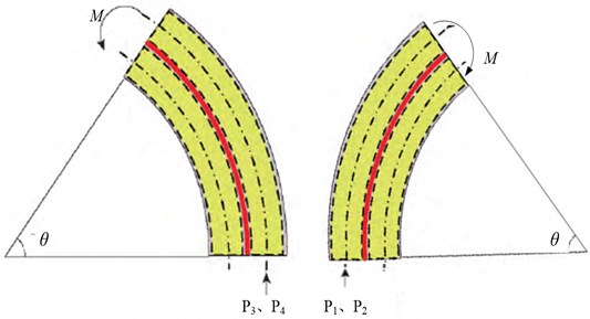
When compressed gas is injected into the manipulator, the latex tube expands and deforms under pressure. Due to the external restraint ring limits the radial deformation of the latex tube, the upper cover is only subject to the axial force and resultant torque generated by the gas. Due to the large axial stiffness of spring plate, it can be assumed that the axial elongation is zero so that the manipulator only occur bending deformation. Therefore, when the 1 and 2 muscles are ventilated, the manipulator is bending in the direction of the 3 and 4. Similarly, when the 3 and 4 muscles are ventilated, the manipulator is bending in the direction of the 1 and 2 muscles (Fig. 3). It is obvious that we could control the bending direction and bending angle of the manipulator by adjusting the value of Pi.
Fig. 1Three-dimensional model
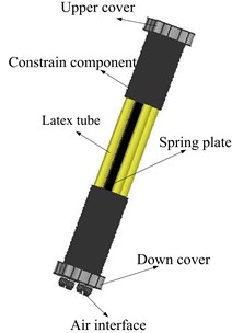
Fig. 2The structure of restraint ring
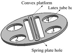
Fig. 3The deformation mechanism of the manipulator
3. Dynamic experiments and analysis
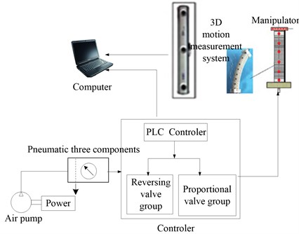
The dynamic experiments of manipulator under different incentive signals were carried out by using the dynamic experimental device. The dynamic experimental device is composed of pneumatic control system, signal control system and 3d motion measurement system, which is shown in Fig. 4. During the experiment, the program of step, pulse and ramp was controlled by computer and PLC. Different air pressure was provided by the air pump to make the manipulator move. The 3D motion measurement system captured and tracked the mark points on the manipulator in order to get the position coordinates. The parameter of the joint is show in the Table 1.
Table 1The parameter of the manipulator
Parameter name | Value |
Total length of the manipulator | 60 mm |
Mass of the manipulator | 666.2 g |
Outer diameter of restrain ring | 62 mm |
Thickness of restrain ring | 3 mm |
Material of spring plate | 65 MN |
Specification of spring plate | 70×12×0.25 mm |
Specification of latex tube | Ø12×15 mm |
The elastic shear modulus of latex tube | 1.367 MPa |
The elastic shear modulus of spring | 79 GPa |
Fig. 4The principle of experiment
3.1. Response analysis under step signal
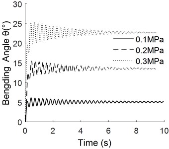
The step signal can be realized through on-off of the switching of the electromagnetic reversing valve. The time-domain response curve of step signal is shown in Fig. 5.
As can be seen from Fig. 5, the bending angle of the manipulator increases with the increase of the pressure. Due to the small damping and large inertia of the manipulator, the overshoot is large and the time required is also long when it reaches the equilibrium position.
Fig. 5Response curve of step signal
3.2. Response analysis under pulse signal
The 1.0 s, 2.0 s and 4.0 s with different pulse width of incentive signals can be set by timer in PLC respectively.
The time-domain response curve under different pulse width is shown in Fig. 6.
From Fig. 6(a) to Fig. 6(c), it can be seen that the stability of the manipulator is poor in the process of pressure relief and the response time to reach the steady state is long. The higher the pressure is, the more obvious the phenomenon is. The main reason is that the bending angle increases with the increase of pressure, and the inertia during pressure relief is relatively large, leading to large overshoot in the process of pressure relief of manipulator.
Fig. 6Response curve under different pulse width
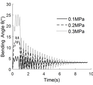
a) Pulse width is 1.0 s

b) Pulse width is 2.0 s
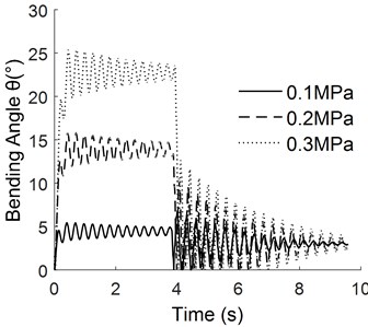
c) Pulse width is 4.0 s
3.3. Response analysis under ramp signal
By adjusting the electrical proportional valve, the ramp signals under different inflation rate can be realized. Fig. 7 is the response curve of different pressure with the same ramp signal. Fig. 8 is the response curve under different ramp signals with the same pressure. In Fig. 8, represents the time required for the pressure value to reach the specified value of 0.2 MPa at a certain inflation rate.
It can be seen from the comparison between Fig. 7 and Fig. 4 that the overshoot is smaller and the stability is better when the manipulator reaches the equilibrium position under the ramp signal. As can be seen from Fig. 8, the response time of the manipulator becomes shorter with the increase of the slope value when the steady state is reached.
3.4. Analysis of frequency domain response
The frequency domain characteristic curves of the manipulator under different pulse widths can be obtained by Fourier transform as shown in Fig. 9. The natural frequency data of the manipulator under the same pressure under different pulse widths were averaged to obtain the curve of the manipulator's natural frequency changing with the pressure, which is shown in Fig. 10.
Fig. 7The response curve of different pressure with the same slope signal
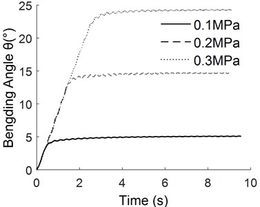
Fig. 8The response curve of different slope signals with the same pressure
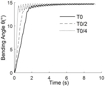
Fig. 9The frequency domain characteristic curves of the manipulator
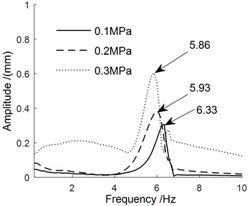
a) Pulse width is 1.0 s
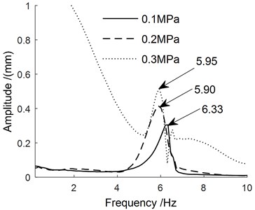
b) Pulse width is 2.0 s
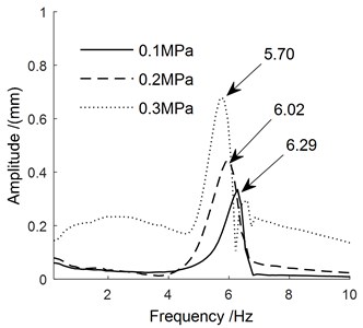
c) Pulse width is 4.0 s
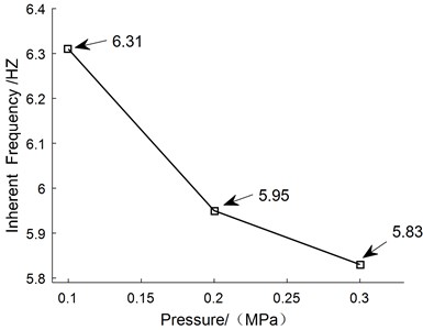
It can be seen from Fig. 9 that the pulse width has a small effect on the inherent frequency of manipulator, and the air pressure has a large effect on it. The natural frequency of manipulator is mainly concentrated in the low frequency region, about 6 Hz. As can be seen from Fig. 10, with the increase of pressure, the rigidity of the overall structure becomes lower after the deformation of the manipulator, resulting in the decline of its inherent frequency.
Fig. 10The curve of inherent frequency with the pressure
4. Conclusions
A new kind of pneumatic flexible manipulator is developed, which has one degree of freedom and can only swing from side to side around the middle spring plate. The dynamic experiments of the manipulator were carried out by using the three-dimensional motion capture system, and the time-domain and frequency-domain responses of the manipulator under different incentive signals were obtained. After bending and deformation, the inherent frequency of the manipulator decreases with the increase of air pressure and it is mainly concentrated in the low-frequency region (about 6 Hz). By comparing the response curves under different signals, it can be concluded that the stability under ramp signals is better than the step signal and the response speed is adjustable, so it can be used as the actual control method of manipulator to reduce vibration impact.
References
-
Department of Economic and Social Affairs Population Revision. World Population Prospects: The 2019 Revisions. United Nations, New York, 2019.
-
Ma Guoqing Research on Structural Design and Optimization of Mobile Service Robot Manipulator. Harbin Institute of Technology, Harbin, 2014.
-
Renda F., Giorelli M., Calisti M., et al. Dynamic model of a multi-bending soft robot arm driven by cables. IEEE Transactions on Robotics, Vol. 30, Issue 5, 2014, p. 1109-1122.
-
Webster III R. J., Jones B. A. Design and kinematic modeling of constant curvature continuum robots: a review. The International Journal of Robotics Research, Vol. 29, Issue 13, 2010, p. 1661-1683.
-
Yan Ji Hong, Shi Pei Pei, Zhang Xin Bin, et al. Review of biomimetic mechanism, actuation, modeling and control in soft manipulators. Journal of Mechanical Engineering, Vol. 54, Issue 15, 2008, p. 1-14.
-
Li Yafeng Design and Research of Motion Control System for the Rope-Driven Flexible Manipulator. Hefei University of Technology, Hefei, 2017.
About this article

The authors would like to thank the Jilin Province Science and Technology Development Program of Jilin Province No. 20170204064GX and No. 20180201050GX, Project of Education Department of Jilin Province No. JJKH20190541KJ, Changchun Science and Technology Program of Changchun City No. 18DY017.
