Abstract
Based on flexible pneumatic joints, a new kind of flexible finger was proposed. The structure and operating principle of the finger was presented. The kinematics equation of the finger was built by homogeneous transformation matrix. Based on the static experiment of joints, the kinematic simulation of the finger was carried out and the motion trajectory of the finger was obtained. The simulation results show that the finger has good flexibility and can complete the functions of forward bending, reverse bending and lateral swing of human hand.
1. Introduction
At present, the common driving form of manipulator mainly includes motor drive, fluid drive and other forms [1]. Electric driven has the advantages of high precision and easy to control, but it has the disadvantages of large volume and poor flexibility [2]. The biggest advantage of hydraulic driven is large thrust, but it has the disadvantages of high cost, poor reliability and easy leakage [3]. In order to overcome the shortcomings of rigid manipulators and combine with the research status and trend of the flexible pneumatic actuator, a flexible finger is designed by using the multi-directional bending joint and unidirectional bending joint. The finger can bend like the human finger and can independently and coordinately control the bending angle of each joint. It has good flexibility and simple structure and can be used in agriculture, picking robot, service robot and other fields.
2. Structure and function of flexible joint
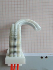
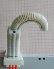
The finger is composed of two joints in series, which is shown in Fig. 1. The base joint is a multi-directional bending joint [4], with an effective deformation length of 50 mm. It is made up of four artificial muscles in parallel. The combination of ventilation of different muscles can realize multi-directional bending and axial extension of the joint. The distal joint is a unidirectional bending joint [5], with an effective deformation length of 60 mm. The joint bends towards the side of the spring plate when compressed gas is injected into the joint.
3. Kinematic model of flexible finger
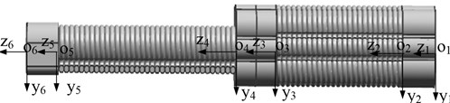
To facilitate the analysis on the position and posture of the finger, the coordinate system - is established, where (1, 2, 3, 4, 5, 6) denotes the feature points on the finger as showed in Fig. 2.
According to the deformation law of each joint and the geometric structure of the connecting piece, the transformation matrix of the two adjacent key points on the finger can be obtained when the fingers are forward bending.
The transformation of coordinates from the end to the other end of the unidirectional bending joint when it is bending can be expressed as:
where is the bending angel of the joint. According to the deformation of the joint and its length, the following equations can be known:
where 16 mm is the distance from the center of the latex tube to the spring plate, 60 mm is the effective deformation length of the joint.
Fig. 1Three-dimensional model of the finger
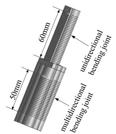
Fig. 2Coordinate system of the finger
Similarly, the transformation of coordinates from the end to the other end of the multi-directional bending joint can be expressed as:
where is the bending angel of the joint. According to the deformation of the joint and its length, the following equations can be known:
where 60 mm is the effective deformation length of the joint, is the elongation of the joint.
The transformation of coordinates from the end to the other end of the connector can be expressed as:
According to the geometric shape of the connector: .
The vector representation of each key point on the finger in the local coordinate system is . The description of any key point on the finger in the root coordinate system can be obtained:
where represents the transformation matrix when the key points on the finger are transformed from the coordinate system to . In the same way, the transformation matrix of the reverse bending and lateral pendulum of the finger can be obtained.
4. Experiment and simulation analysis
The changes of elongation and bending angle with air pressure were obtained by static experiments, which are shown in Figs. 3-5 respectively.
Fig. 3The curve of the elongation and pressure of multi-directional bending joint
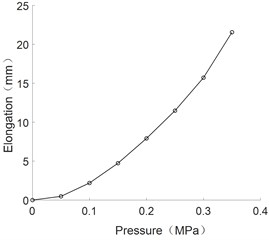
Fig. 4The curve of bending angle and pressure of unidirectional bending joint
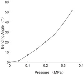
Fig. 5The curve of bending angle and pressure of multi-directional bending joint
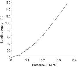
As can be seen from the figure, the bending angle of flexible joints and the axial elongation are positively correlated with the pressure value.
The experimental data were fitted by quadratic polynomial and the corresponding empirical formula was obtained as follows:
where is the elongation of the of multi-directional bending joint, is the value of air pressure:
where is the elongation of the of multi-directional bending joint:
where is the bending angle of the of unidirectional bending joint.
The pneumatic control principle of the finger is shown in Fig. 6, which is composed of six electric proportional valves and five electromagnetic directional valves. The electromagnetic directional valve is used to control the air pressure on and off and the proportional valve is used to regulate the gas pressure. Fig. 7 shows the different postures of the finger.
Fig. 6The pneumatic control principle
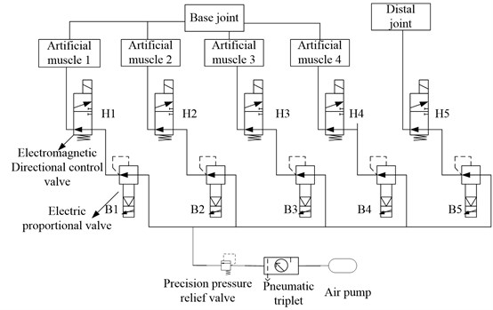
Fig. 7Different gestures of the finger
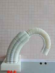
a) Forward bending
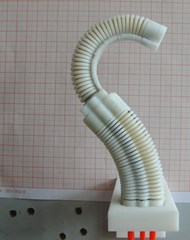
b) Reverse bending
c) Lateral swing
d) Lateral swing
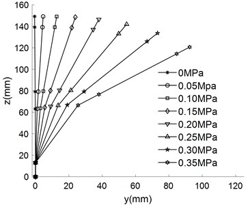
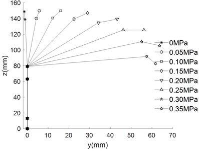
The empirical formula above are substituted into kinematic equation to obtain the different movement trajectory of the finger, which are shown in Fig. 8.
As can be seen from Fig. 8, the bending angle of the finger increases with the increase of air pressure under different driving modes. When the pressure is 0.35 MPa, the forward bending angle reached 208.8°, the reverse bending angle is 105.2°, the lateral swing bending angle is 51.51°. The base joint is multi-directional bending joint, which can be deformed in the plane (Fig. 5(a) to Fig. 5(d)). The base joint can also be deformed in the plane (Fig. 5(e) to realize the side swing function of the finger.
Fig. 8Different movement trajectory of finger
a) Base joint drives independently
b) Distal joint drives independently
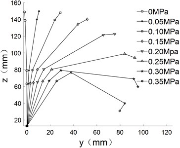
c) Forward bending
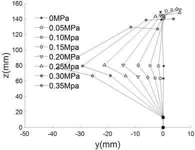
d) Reverse bending
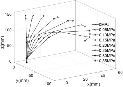
e) Lateral swing
Through the comparison between the real experiment of fingers and the kinematic simulation results of flexible fingers, it can be seen that the simulation results of finger deformation are basically consistent with the experiment results, which shows that the established kinematic model of flexible fingers can well describe the deformation of fingers.
5. Conclusions
1) The biggest characteristic of the finger developed in this paper is that it is directly driven by artificial muscle, does not need decelerating device and transmission device and has certain elasticity and good cushioning.
2) The static experiment of the flexible joint is carried out and the change rule of the bending angle and the axial elongation of the joints with the air pressure is obtained. When the air pressure is 0.35 MPa, the maximum bending angle of the multi-directional bending joint is 51.51°, the maximum axial elongation is 21.56 mm; the maximum bending angle of the unidirectional bending joint is 153.2°.
3) The kinematic equation of the finger is established by using the homogeneous coordinate change matrix and the movement trajectory of the finger is obtained and verified by experiments. The maximum bending angles of forward bending, reverse bending and lateral swing were 208.8°, 105.2° and 51.51° respectively when the air pressure is 0.35 MPa. The experimental and simulation results show that the finger movements are flexible, which can realize forward bending, reverse bending and lateral swing. The complex gesture and grasping action can be realized by the cooperation of multiple flexible fingers.
References
-
Rus D., Tolley M. T. Design, fabrication and control of soft robots. Nature, Vol. 521, Issue 7553, 2015, p. 467-475.
-
Liu H., Butterfass J., Knoch S., et al. A new control strategy for DLRs multisensory articulated hand. IEEE Control System, Vol. 19, Issue 2, 1999, p. 47-54.
-
Akihiro Yamaguchi, Kenjiro Takemur, Shinichi Yokot, et al. A robot hand using electro-conjugate fluid. Sensors and Actuators A: Physica, Vol. 170, 2011, p. 139-146.
-
Geng Dexu Research on Bidirectional Bending Active Pneumatic Flexible Joint and Its Application in Robot Hand. Jilin University, Jilin, 2011.
-
Liu Xiaomin, Wang Yiqiang, Geng Dexu, et al. Dynamics investigation on bidirectional active flexible bending joints. Advanced Materials Research, Vol. 422, 2012, p. 529-533.
About this article

The authors would like to thank the Jilin Province Science and Technology Development Program of Jilin Province No. 20170204064GX and No. 20180201050GX, Project of Education Department of Jilin Province No. JJKH20190541KJ.
