Abstract
The application of algorithm of solution of incorrectly specified problem is considered to correct the geometry of satellite pinions axes according to the results of indirect measurements. Based on the results of the excessive number of measurements and due to the presence of measurement errors, the probable geometry of the reduction gear box axes location and the necessary corrections are calculated using the least squares method.
1. Introduction
Operability, strength and vibration activity of reduction gears made according to the planetary scheme to a great extent depends on uniformity of load distribution over the parallel flows of transmitted power (between satellites) [1, 2]. In its turn, compliance with this condition is largely determined by errors in manufacture and assembly of satellite nodes [3, etc.].
In the paper [1] it is proposed to minimize specified errors during assembly of reduction gear box by the adjustment of intercenter distances of satellites by means of eccentric plugs installed in bores of carrier for support necks of their axles. In order to implement this proposal, it is necessary to determine as precisely as possible the actual values of satellite node errors, which, as the experience of one of the leading Russian manufacturers of high-power planetary reduction gears shows [3], is a rather non-trivial task.
The considered errors are calculated from the data of accuracy control checklists, filled by the manufacturer’s TCI specialists on the basis of the results of direct and indirect measurements of primary errors in the production of planetary stage elements within the framework of the “complex accuracy parameter” (CAP) of the planetary mechanism.
Initially, the “CAP” was developed for planetary reduction gears with spur gears [1]. Subsequently, it was extended to chevron engagement and repeatedly clarified [4, etc.] The last updated version of the “CAP” was given in [5], where on the basis of experimental data the correlation of the specified parameter with vibration of planetary reduction gear at the frequency of tooth overrunning was revealed.
According to [5], complex errors of production and assembly of satellite nodes of a chevron planetary reduction gear are determined taking into account the error of total clearances in the engagement of satellite pinions with central wheels, accumulated errors of distances between bores for axes of adjacent satellites in cheeks of a carrier (hereinafter – chordal intercenter distances). At the same time, the greatest difficulties arise with the high-precision definition of chordal distances, which is connected with the lack of modern high-precision equipment in most Russian manufacturers of high-capacity reduction gears, that allows to obtain coordinates of racks of as large and complex geometry of units as a carrier by direct measurements.
2. The problem definition
In practice, errors of mutual arrangement of bores in the carrier are determined by the results of measurement of intercenter distances and crossing of special check shafts, installed with preset accuracy in the specified bores. In general, chordal intercenter distances and distances between the axes of the satellite pinion bores and the central axis of the carrier are the subject of measurements on each of the carrier cheeks. Axle crossings are defined for pinion carrier bores relatively to the central axis and between axes of adjacent pinion bores for satellites.
In the paper [1], it is recommended that only chordal intercenter distances are to be used to determine the desired errors in the manufacturing of the carrier, disregarding all other measurements.
However, a reduction in the number of primary data, measurement errors, and the possibility of human-related errors in the measurement results can lead to a significant deviation of the results of the desired manufacturing and assembly errors from their actual values. The purpose of the paper is to build a mathematical model capable to take into account all available measurement results.
3. The development of the mathematical model
In order to increase the accuracy of determination of CAP, the mathematical model and the algorithm of numerical solution are proposed, which allow to obtain sought coordinates of bores for satellites in the carrier taking into account all controlled parameters. Let’s consider the developed model using the example of determining the coordinates of bores in the carrier of a planetary stage with five satellites. In order to make a model, we introduce a Cartesian coordinate system with a center in the plane of one of the cheeks of the carrier (let’s call it left) so that the central bores of the carrier determine the coordinate axis , and the center of the bore for the axis of the first satellite pinion determines the direction of the coordinate axis .
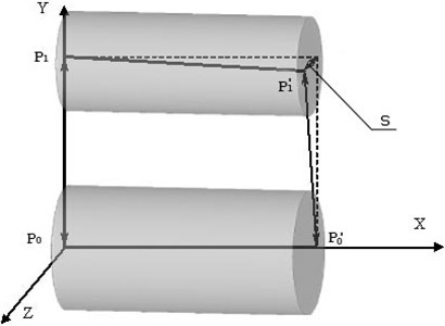
The parameters required to construct the mathematical model are illustrated in Figs. 2-3. In Fig. 1 points and indicate centers of the left and right bores of the carrier for the support necks. Points and are bore centers for the axis of the first satellite pinion. Here and further, the stroke in the point symbol indicates that the point belongs to the right cheek of the carrier, and the absence of the stroke indicates the left (base) one. Due to manufacturing errors, point may deviate from the plane defined by points , , and , the value of this deviation characterizes crossing of the axis of the first satellite pinion relatively to the central axis of the carrier taken as the base (axis , Fig. 1).
Fig. 1The diagram of measurement of mutual arrangement of bores for axle of the first satellite pinion relatively to the central axis of the carrier
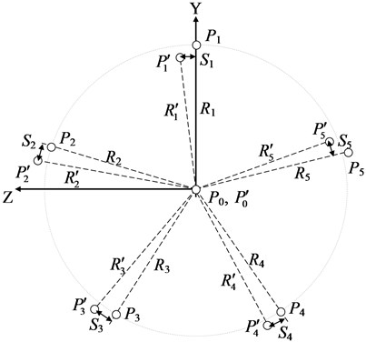
As a result of measurements of radial intercenter distances of a carrier values -, -, - (Fig. 2) are defined. For positive value on Fig. 2 point shift relatively around axis (axis ) counterclockwise is accepted, if to look from the end of axis , strokes designate the centers of boring on the right cheek, without strokes – on the left one.
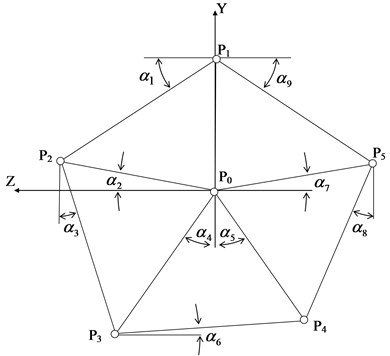
By the measurement of chordal intercenter distances of a carrier and crossings of axes of the adjacent borings for satellites, values (Fig. 3), and (crossing of the axes of the adjacent satellites) where 1-5, are defined. Due to the cyclical indexing, we have , . The centers of the bores are numbered counterclockwise when viewed from the end of the axis.
Fig. 2The view at the centers of a carrier borings (Pi, Pi') from the end of axis X
Since both cheeks of the carrier are parallel, i.e. the centers of all bores lie either in the plane (the left cheek) or in the plane parallel to (the right cheek), the task is reduced to two-dimensional.
Taking into account, that points are accepted as base ones, and the direction of axis is defined by the center of the first bore (coordinate of point is zero) as unknown, we have - coordinates of the bore centers for the axis of satellites on the left and right cheeks, i.e. 19 quantities.
By marking the angular deviations of the geometry elements from the horizontal and vertical lines, as it is shown at Fig. 3, a system of 19 trigonometric ratios linking the measurement results and the coordinates of the bore centers on the left cheek of the carrier (9 unknowns) can be written:
The similar 20 equations can be written in relation to - coordinates of bore centers on the right cheek (10 unknowns) – a system of Eq. (1a):
where is the angle between the || and the vertical axis (Fig. 2).
The angular values of in the resulting systems of equations are taken on the assumption that the points (Fig. 3) and form regular pentagons. In reality, if there are errors in the manufacturing of the carrier, the correctness of these pentagons is violated. Therefore, the dependence of the calculated coordinates on the measured parameters is non-linear, and the Eq. (1) and (1a) are a linearized mathematical model that allows to get acceptable for practical use approximate solutions.
By the results connected with the crossing of satellite axis relatively to the central axis (parameter of Fig. 1) and adjacent axes of satellites relatively to each other, more 19 equations were written:
After combining Eqs. (1), (1a), and (2), we obtain a system of 58 equations with the respect to 19 unknowns, which is suitable for calculating errors of a carrier manufacturing, taking into account all the parameters controlled by the manufacturer (in accordance with the assigned task).
Fig. 3The scheme of the bore centers in the plane of the carrier cheek YZ (P) and angular values for trigonometric ratios (α)
It should be noted that the obtained system of equations is redefined (the number of written equations exceeded the number of unknowns) and incompatible (due to inevitable measurement errors), i.e. it has no exact solution. In mathematics, such tasks are commonly called incorrectly defined. The solution is sought by the least squares method.
In the process of debugging of program code at the decision of test problems the computational difficulties related to the bad conditionality of the matrix of the system of equations were revealed: small deviations in basic data result in the considerable changes of results of calculation, in addition, errors in rounding off, related to the eventual dimension of registers of calculation machine, result in bad convergence of iterative process and large calculation errors.
These problems were solved by using software “Wolfram Mathematica” [6], which was developed to perform symbol calculations. “Wolfram Mathematica” allows making calculations without the rounding errors, with any, by the exactness set in advance, using an analytical decision.
4. Conclusions
The novelty of the proposed procedure is that it enables to take into account all available indirect measurement results, but not only a part of them, and allows to increase the accuracy of calculation of complex errors of manufacturing and assembly of satellite nodes without additional costs.
Accordingly, knowing the error values of manufacturing and assembling of satellite nodes, they can be compensated by installing eccentric plugs, as it was said in the introduction.
The practical value of the article is in the development of the special software, that makes it possible to minimize the impact of indicated errors on the exploitation properties of the planetary mechanism more correctly and efficiently.
References
-
Ayrapetov E. L., Genkin M. D. Statics of Planetary Mechanisms. Nauka, Moscow, 1976, p. 264.
-
Ayrapetov E. L., Genkin M. D. Dynamics of Planetary Mechanisms. Nauka, Moscow, 1980, p. 256.
-
Leontyev Yu A., Yampolsky I. D., Khomyakov V. P., Leontyev M. Y. Experience in creating high-power marine gearboxes at the Kaluga turbine plant. Jubilee Collection of Works of the Research Center “Kaluga Turbine Plant”, Kaluga, 2002, p. 134-144.
-
Leontiev Yu M. Research of Static Loading of Powerful Ship Planetary Gearboxes. Ph.D. Thesis, Moscow, 2001, p. 229.
-
Leontiev Yu M., Polunin I. V., Lysenkov V. S. Analysis of the impact of precision manufacturing of turbo gearboxes on vibration activity. 5th Scientific and Technical Conference “View to the Future”, 2007, p. 319-328.
-
The System for Current Technical Computations, https://www.wolfram.com/mathematica/.
About this article

