Abstract
The aim of this paper is to develop a software which allows to determine the run-down of the rope in boom systems of portal cranes instead of the existing graph analytic methods in order to profile the crane trunk to ensure the movement of the cargo only along the horizontal path when the boom system departure changes. The universal analytical dependencies to determine the rope run-down were obtained, lines of equal run-down of the rope for hinged boom systems were stated. Due to the results of the calculations which were carried out with the help of the developed software, it became possible to obtain nomograms that allow designers to determine the necessary parameters of the boom system taking into account the rope run-down.
1. Introduction
The main feature of portal cranes is the design of boom devices, which ideally should allow the cargo to move along the horizontal trajectory, ensuring that its potential energy remains unchanged. The analysis of the existing calculation methods of hinged boom systems with a profiled trunk shows, that the proposed methods are based on graph analytic constructions which are labour-intensive and require repeated selection of parameters and their further verification, that is not useful for the development of automated design systems of portal crane elements [1-3].
It also should be noted that in the CIS countries there is a question of guaranteeing safe operation of lifting cranes [4-6]. The design of new elements of portal cranes instead of non-repairable cranes can be simplified by the design automation. The data presented in the article are the logical development of the papers described in [7-9] and expand significantly the capabilities of the already developed software.
2. Analytical dependencies to ensure the cargo movement along the horizontal trajectory
Fig. 1 shows the kinematic diagram of the hinged boom system of the portal crane in two positions with the cargo rope connected. The hook movement down along with the change of a tilt angle of a boom of a hinged boom system in the range from the initial to the final is determined by the following dependence:
where is a lifting height of the end point of the profiled trunk; is the amount of the run-down of the rope; is the amount of the lifting (sampling) of the rope due to the difference in the length of the girth arcs of the circumference blocks of the cable system; is a multiplicity of the polispast rope system.
Thus, the condition for cargo moving along the horizontal trajectory is:
Fig. 1The kinematic diagram of the hinged boom system of a portal crane
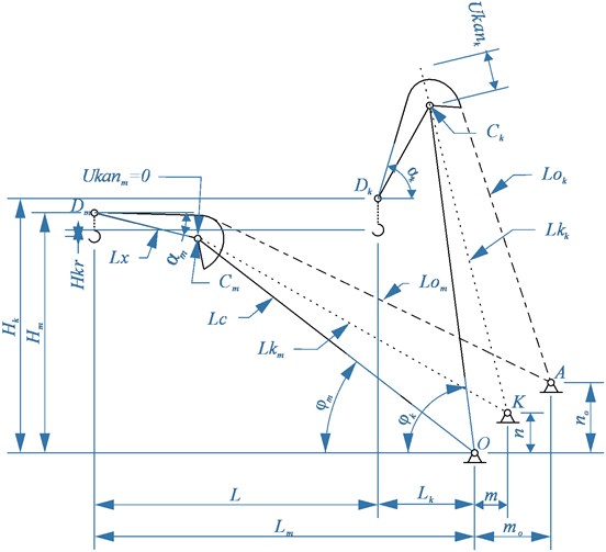
The practical condition Eq. (2) can be realized by finding the total value of the rope lowering (run-down) with the dependence of , by building reverse trajectory of the height of the trunk end point and by building the profiled part of the trunk with the respect to the previous reverse trajectory.
According to the scheme it can be stated, that the length of the rope branch at maximum run-down is larger than the rope branch at the final run-down, the value of the rope run-down (lowering) at the final position can be determined according to the following dependence:
The calculations performed for an existing crane, in which the boom and trunk are to be replaced, showed, that the lift value (sample) of the rope taking into account the multiplicity of the polispast does not exceed the recommended [1-3] . The elasticity of a rope of considerable length also introduces some uncertainty in determining the total amount of the rope run-down, that is why in the dependence Eq. (2) the difference between the girth arcs of the blocks can be ignored, so the dependence may be introduced as the following:
While determining the parameters of the boom and of the front trunk shoulder according to the dependences from [7-9] to prevent the cargo lowering at the change of tilt angle of the boom, the opportunity to lift axis D of the end trunk block by the amount of rope run-down, taking into account the multiplicity of the polyspast was taken into consideration: Lifting of the point of the truck end is equal in absolute value to the total rope run-down at the final position of the hinged boom system.
3. The analytical dependences to determine the rope run-out
The general equation of the rope run-down at the final position of the hinged boom system and related parameters is determined according to the scheme of the mechanism (Fig. 1) by projections on horizontal and vertical axis of lengths of the rope branches and :
where , are the position of the end point of the trunk in the initial and final position respectively of the hinged boom system on the horizontal and vertical axis; is a service area of the crane on the horizontal axis; is the length of the trunk; , is the position of the point of the cargo rope drum axis; , is the angle of inclination of the trunk in the initial and final positions, respectively.
On the other hand, the maximum rope run-out equation can be defined as:
where is the length of the boom of the hinged boom system of the portal crane.
Determining the coordinates of the position of the point of the drum axis can be performed according to the dependence Eq. (6) after converting the equation with the respect to the coordinate by the coordinate specified in the range (0,..., 0.4) [1-3].
The results of calculation of point for the hinged boom system of the existing crane, which needs the boom and the trunk to be replaced, within the specified range of the rope run-down from 0 to 10 m, are presented on Fig. 2.
Fig. 2Lines of equal run-down of the rope in final position, obtained by dependencies (6, 7)
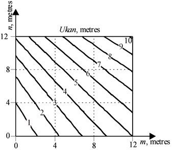
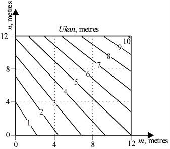
Fig. 3Lines of equal run-down of the rope in final position, obtained by dependencies (8, 9)
The visual analysis of Fig. 2 shows that the geometric location of the points , providing at constant parameters for specified conditions (, , or , , ) the equal value of the rope run-down in a final position of a hinged boom system is a straight line.
In order to confirm the hypothesis of the presence of an equal rope run-down line, there were coefficients , found in the equation of straight lines by solving the systems of Eqs. (7, 8):
where is the length of the rope branch at the initial position of a hinged boom system in case, when :
where is the length of the rope branch at the initial position of a hinged boom system in case, when .
The comparison of the graphs presented in Figs. 2, 3 shows their almost complete identity, the standard deviation lies in the range of 0.0001,..., 0.0003 meters, therefore, the assumption that there is an equal rope run-down line at the final position of the hinged boom system is reasonable.
Fig. 4 shows the nomogram of change for the case when 1 meter in the operating range of the boom angle change of a hinged boom system –20°,…, 80° and the position of point on the line providing an equal cable run-down; Fig. 5 shows just the same, but for the case when 2 meters respectively.
Fig. 4The dependence of a rope run-down on a boom tilt angle at the position of point Km,n on the line of an equal run-down of the rope at final position, Ukank=1 meter
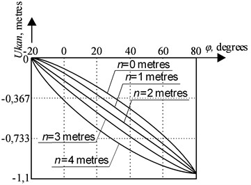
Fig. 5The dependence of a rope run-down on a boom tilt angle at the position of point Km,n on the line of an equal run-down of the rope at final position, Ukank=2 meters
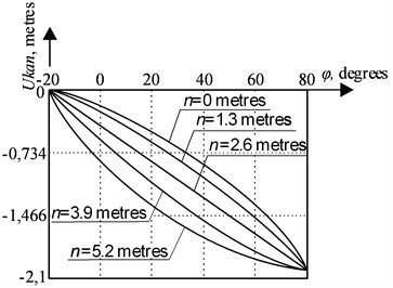
According to Figs. 4, 5 it can be concluded that when the position of point changes on the line, which provides an equal rope run-down, the trajectory of the rope run-down changes too along the vertical, depending on the angle ; at the same time rope run-down values at the initial position of a hinged boom system and at the final position respectively, remain unchanged. Taking into account the dependence Eq. (2) and also an opportunity to vary value, it has an impact on profiling of a trunk, and, further, on a possibility to receive a number of profiles in order to choose an optimal one.
To make a complex analysis of the front shoulder of the hinged boom system of the crane taking into account the rope run-down, a system of equations was solved, which included dependencies Eqs. (5, 6), as well as dependencies Eq. (9) described in [7, 8]:
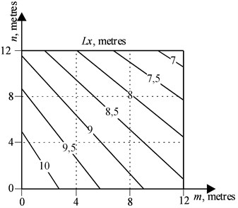
On Figs. 6-9 the nomograms are presented which have been received at the solution of a system of the Eqs. (6, 7, 10), relative to basic data, , , for the portal crane at which the boom and the trunk are to be replaced: the nomogram on Fig. 6 is a family of lines of an equal rope run-down , the nomogram on Fig. 7 is a family of lines of an equal rope run-down taking into account the multiplicity of the polyspast , Figs. 7 and 8 is a family of lines to determine the length of a boom and of a trunk according to the chosen values or , and also according to the coordinates . This version of presentation of calculation results is the most informative and is recommended for the main application, because by specifying the required values on one of the nomograms, the designer can get all the necessary parameters with the help of others.
Fig. 6Lines of an equal rope run-down at the final position Ukank

Fig. 7Lines of an equal rope run-down at the final position, taking into account the multiplicity of the polyspast Ukank/pk
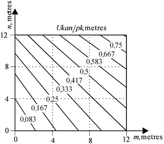
Fig. 8The geometric location of points Km,n to determine the boom length Lc

Fig. 9The geometric location of points Km,n to determine the length of the trunk Lx
The above-described dependencies were implemented as a graphical interface module to perform rope run-down and hook drop calculations when changing the swing of the portal crane’s hinged boom system in a Python 3 programming language environment using SymPy, Matplotlib libraries.
4. Conclusions
The practical value and the novelty of the paper are as follows.
Analytical dependencies are obtained for the determination of the rope run-down value in hinged boom systems of portal cranes. The proposed technique is universal for all cases of the cargo rope location relatively to the boom.
As the result of the studies, it was found that there are lines of equal run-down of rope for the final position of hinged boom systems of portal cranes. It is shown that the movement of the axis point of the load rope drum along the equal run-down line leaves the predetermined run-down of the rope constant in the initial and final positions, at the same time it has a significant impact on the run-down path between these positions, which will further affect the shaped part of the trunk and the ability to obtain a number of profiles in order to choose the optimal one.
The procedure of the determination of rope run-down value in hinged boom systems of portal cranes is implemented in the presented software. The correctness of the received results is confirmed by test calculations.
References
-
Gorskiy B. E. Articulated Bends of Planetary Cranes. Machine Building, Moscow, 1965, p. 185, (in Russian).
-
Bortyakov D. E., Orlov A. N. Special Load-Lifting Cars / Portal, Ship and Floating Cranes. Saint-Petersburg, 2009, p. 160, (in Russian).
-
Novikov S. P. Classification of kinds of trajectories of moving of a cargo by the gantry crane. Journal of Volga State Academy of Water Transport, Vol. 4, 2003, p. 151-158, (in Russian).
-
Leonova O. V., Daryukhin A. B. Examination of operability of elements of metal structures of portal cranes with deformation damages with the magnetic control method. River Transport, (XXI century), 2009, p. 65-68, (in Russian).
-
Rozovsliy N. Y. Ensuring safe operation of portal cranes that have completed the standard service life. Basic Engineering Industry, Vol. 1, 2006, p. 28-30, (in Russian).
-
Nemchuk О., Hredil М., Pustovoy V., Nesterov О. Role of in-service conditions in operational degradation of mechanical properties of portal cranes steel. Procedia Structural Integrity, Vol. 16, 2019, p. 245-251.
-
Raevsky V. A., Strelov V. I. Synthesis of off-axis link-slider mechanism with variable eccentricity. Interuniversity Scientific and Technical Conference “Hoisting-and-transport equipment”, Bauman Moscow State Technical University, Moscow, 1997, p. 32, (in Russian).
-
Raevsky V. A., Strelov V. I. Calculation of boom and front arm of portal crane trunk. Russian Scientific and Technical Conference “Socio-Economic Problems of Production Management”, Bauman Moscow State Technical University (Kaluga Branch), Kaluga, 1997, p. 173, (in Russian).
-
Raevskiy V. A., Nosov V. A. Geometric synthesis of boom and front shoulder trunk hinged boom system. News of Tula State University. Technical science, Vol. 7, Issue 1, 2013, p. 166-171, (in Russian).
About this article

