Abstract
A gear-bearing coupling dynamic model that includes bearing stiffness, mesh stiffness and mesh errors for a herringbone planetary gear set (HPGS) is proposed. The proposed model is used to predict the random stress process of the gears and bearings along with Monte Carlo simulation, when the effects of tooth surface wear on meshing errors are considered. A calculation model for the random strength process is derived by applying the linear fatigue damage criterion and regarding the Poisson random process as a counting process of the random stress. Assuming that the stress and strength are random processes, a time-dependent reliability model for HPGS with failure dependency is proposed to predict the time-dependent reliability of HPGS based on the failure mode groups that are obtained by the correlation coefficient. The results show that, the meshing errors caused by the tooth surface wear, make the dynamic loads and failure dependency of the parts of HPGS gradually increase over service time. At the same time the fatigue damage, which is caused by the load action, makes the strength of parts of HPGS gradually decrease over service time. Therefore the reliability of HPGS quickly decreases over service time. If the shafts of the planets and sun gear are free in their axial direction, the failure dependency of the parts will significantly decrease, and the reliability of a herringbone planetary gear set will significantly be improved.
1. Introduction
Herringbone planetary gear set (HPGS) has more compact structure and higher power density than herringbone gear set or planetary gear set. Therefore it is usually used in heavy load machineries, such as wind turbine and coal cutter. The engineering practice shows that the failure of these machineries mainly results from the failures of the transmission system [1, 2]. So, the study on reliability predication and optimization design of HPGS has significant value for improving the reliability of the aforementioned heavy load machineries.
The load-strength interference theory put forward by Freudenthal [3] is widely used for the reliability analysis of a mechanical part or system [3-15]. This theory is based on the concept that the failure of a part depends upon a load variable and a strength variable, both can be described by a probability density function. The reliability of a mechanical part or system is defined as the probability when the strength variable exceeds the load variable. However, the load variable and strength variable of a system are difficult to be obtained by experiment or theoretical calculation method, so the load-strength interference theory can’t be directly used in the reliability analysis of a mechanical system. As the state of the system (normal or failure) is determined by the states of the parts, the early researchers [4-6] constructed the reliability model of a mechanical system in terms of the logical system (series, parallel, voting and hybrid system) that is made of the failures of all parts in the mechanical system. In order to reduce the complexity of the proposed reliability model, it is based on the assumption that the failures of the parts are independent of each other and the distribution of the stress and strength are unchanged.
However, in practical application, as the dynamic load and strength of the parts change with service time, the reliability of the mechanical parts or system is time-varying. So the prediction results obtained by the proposed model in [4-6] usually have a large error, even is incorrect. In order to solve the problem in estimation of the time-dependent reliability of the mechanical parts and system, some researchers [7-10] proposed the time-dependent reliability model of the parts and system by assuming that the loads and strength of the parts are random process and ignoring failure dependency. Though the proposed model can correctly predict the time-dependent reliability of the mechanical parts, it can’t correctly predict that of a mechanical system as failure dependency of the parts is ignored. In order to correctly estimate the reliability of a mechanical system with failure dependency, Gao et al. [11] constructed a reliability model for a mechanical system with failure dependency and strength degradation of mechanical parts to analyze the reliability of the system and its parts. Paolo Bucci et al. [12] presented a method that combines Markov modeling with the cell-to-cell mapping technique (CCMT) to construct dynamic ETs/FTs. Salvatore Distefano et al. [13] applied state-space model based analytical techniques in the modeling and the estimation of dynamic reliability and availability of systems with non-exponential distributions, and identified some dynamic reliability behaviors, such as the common cause failure, the fault coverage and the load sharing. Chen et al. [14] proposed a new probability density evolution approach for evaluation of the extreme value distribution and dynamic reliability assessment of nonlinear structures with uncertain parameters. Based on the probability perturbation technique, the second moment method and the probability network evaluation technique, LU et al. [15] constructed a reliability model for a structure system with multiple failure modes, and firstly represented failure dependency by the correlation coefficients between failure modes.
Above all, though a lot of work has been done on the estimation of the time-dependent reliability of a mechanical system with failure dependency, the researches on the time-dependent reliability of HPGS with failure dependency haven’t still been carried out, especially an effective calculation method for the distribution parameters of the stress and strength random process of the parts. So, in order to correctly estimate the reliability of HPGS under random loads, in this paper, firstly a dynamic model for HPGS is constructed to calculate the dynamic responses of the parts in HPGS when tooth surface wear is considered, and the load random process of the parts is obtained by Monte Carlo simulation and the proposed dynamic model and then a calculation model is constructed to obtain the strength random process of the parts when fatigue damage is considered. Finally, based on failure mode groups obtained by the coefficient correlation, a time-dependent reliability model with failure dependency for HPGS is presented to predict the time-dependent reliability of HPGS under random loads.
2. Dynamic modeling of a herringbone planetary gear set
2.1. Gear-bearing coupling dynamic model for HPGS
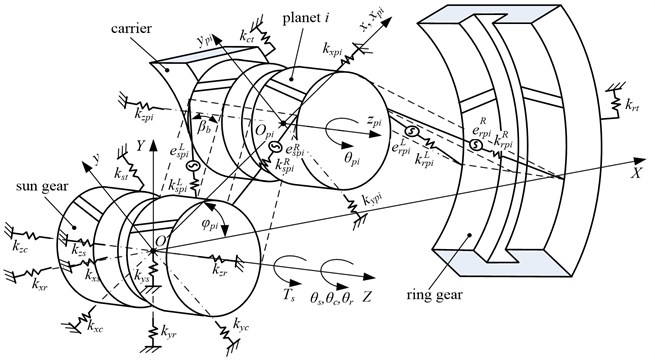
Figure 1 illustrates a gear-bearing coupling dynamic model for a herringbone planetary gear set. In this model, Gears and carrier are considered as rigid bodies. Bearings are modeled by linear springs. The gearmesh is modeled by linear springs acting on the lines of action. The effects of viscous damping and gravity on dynamic characteristics are ignored. In Fig. 1, the subscripts , , and respectively denote the carrier, sun gear, ring gear and planets, and the subscript ( 1, 2,…, , where, indicates the number of the planets) is the ordinal number of planets. is a static coordinate system. is a moving coordinate system of the carrier, which is fixed to the carrier and rotates with a constant angular velocity . is a moving coordinate system of the planet , which is fixed to the carrier, and the origin of coordinates is located at the geometric center of the planet .
The effects of the center position errors of parts on the meshing angle are ignored. The tangential and axial dynamic meshing forces of sun-planet pairs are respectively given as Eqs. (1) and (2):
where, represents the helix angle of a herringbone gear on the base cylinder, and respectively represent the meshing stiffness of left side and right side of sun-planet pairs, and respectively represent the meshing errors of left side and right side of sun-planet pairs, and can be calculated by Eq. (15), and respectively represent the relative mesh displacement of left side and right side of sun-planet pairs along the lines of action, and are given by Eqs. (3) and (4), respectively.
where, is the transverse pressure angle of a sun-planet pair, and , where is the position angle of the planet .
Fig. 1Gear-bearing coupling dynamic model for a herringbone planetary gear set
Similarly, the tangential and axial dynamic meshing forces of ring-planet pairs are respectively given by Eqs. (5) and (6):
where, and respectively represent the meshing stiffness of left side and right side of ring-planet pairs, and respectively represent the meshing errors of left side and right side of ring-planet pairs, and respectively represent the relative mesh displacement of left side and right side of ring-planet pairs along the lines of action, and are respectively given by Eqs. (7) and (8):
where, is the transverse pressure angle of a sun-planet pair, and .
The relative displacement between the planet and carrier in - direction and - direction of the coordinate system are given by Eqs. (9) and (10), respectively:
The positive direction of the generalized coordinates is depicted as shown in Fig. 1, and the generalized coordinate vector is given by Eq. (11):
where, , and (the subscript , , , 1,…, ) denotes -direction, -direction, and -direction translational displacements of gear , and , are the base radius deflections, where is base circle radius for the sun, ring, and planets and the radius of the circle of the carrier passing through the planet centers, and is the angular displacement of the carrier, sun, ring, and planets.
The differential equations of motion for HPGS shown in Fig. 1 are given by Eq. (12):
where, the mass matrix , the gyroscopic matrix , the support stiffness matrix , the meshing stiffness matrix , the centripetal stiffness matrix , the generalized force array and the meshing error excitation array , are all (12+4) dimensions.
2.2. Meshing errors considering the effects of tooth surface wear
When a herringbone planetary gear set works under the applied load, tooth surface wear increases with times of load action [14-16]. And tooth surface wear will change mesh errors by changing profile deviation. So in order to accurately obtain dynamic force of gear set, the effects of tooth surface wear on meshing errors must be considered.
2.2.1. Calculation of profile deviation considering the effects of tooth surface wear
Firstly, a fixed surface grid is defined in the active surface of the tooth of interest (for both gears of a gear pair) by defining equally spaced grid lines in the involute direction and equally spaced grid lines in the face width direction. Then, a contact mechanics model, constructed by a quasi-static contact analysis, is used to calculate the contact pressures of point of the tooth of the driving gear or driven gear at a given rotational position . Finally, a local point on one of the contacting gear surfaces is calculated by the Archard’s wear equation [20], and the profile deviation at nodes of gears and accumulated after the th pressure update is given by Eq. (13) [17]:
where, is the initial profile deviation of the driving gear or driven gear , which is caused by manufacturing errors, and is the total wear accumulated at node of gears and after the th pressure update.
2.2.2. Calculation of meshing errors
After profile deviation that is caused by tooth surface wear is calculated by Eq. (13), meshing errors that are caused by profile deviation and pitch deviation can be derived from the geometric contact analysis [21] for herringbone gear pairs, and given by Eq. (14):
where, and are the amplitude and initial phase angle of meshing errors that are caused by profile deviation and pitch deviation , (usually 3-5) is the harmonic order, and is the mesh frequency, and , where denotes the shaft frequency, and denotes the tooth number of a gear.
When the effects of eccentric errors of gears on meshing errors are considered, meshing errors that are caused by manufacturing errors are given by Eq. (15):
where, is the initial phase angle of eccentric errors of gears.
3. Dynamic stresses of a herringbone gear and rolling bearing
3.1. Dynamic bending and contact stress of a herringbone gear
The main failure modes of a herringbone gear include tooth root bending and tooth surface contact fatigue. And the dynamic tooth root bending stress of herringbone gears is given as Eq. (16):
where, is the tangential dynamic meshing force, and can be calculated by Eqs. (1) and (2), is the tooth width, is the normal module, is the transverse pressure angle, is the correction coefficient of the tooth profile, is the correction coefficient of the stress, is the coefficient of contact ratio, and is the coefficients of helix angle.
When the pitch point is taken as calculating points, according to Hertz contact theory, the dynamic tooth surface contact stress of herringbone gears is given as Eqs. (17):
where, is the pitch circle diameter, is the ratio of tooth number between the driving gear and driven gear, is the elastic coefficient, is the area coefficient of the pitch point, is the coefficient of contact ratio, and is the coefficients of helix angle.
3.2. Dynamic contact stress of a rolling bearing
According to Hertz contact theory, the dynamic contact stress of a rolling bearing is given as Eq. (18):
where, is the radial dynamic load of rolling bearings, is the bearing stiffness, , are vibration displacement of the bearing and can be calculated by Eq. (12), and are the Hertz contact coefficient, is the sum of principal curvatures of contact bodies, is the number of rolling elements, is the contact angle between contact bodies under load, and for steel to steel contact [22], .
4. Calculation of strength considering strength degradation
The strength of parts gradually decreases with times of load action, until it is lower than the stress that is caused by the applied load and parts failure. So it is closely related to initial strength and fatigue damage that are caused by a random load.
According to the linear fatigue damage criterion, the mean value of fatigue damage that is caused by one time of random load action [11] is given by Eq. (19):
where, and are the parameters related to material, stress ratio, and loading mode, is the probability density function (PDF) of the random load .
If the Poisson random process is regarded as the counting process of the deteriorating random processes of the stress, and after parts have worked for hours, the probability of times of random load action is given by Eq. (20):
where, is the change rate of a random process.
After the part has worked for hours, the mean value of the fatigue damage caused by the random load is given by Eq. (21):
where, the maximum stress cycle times after the part has worked for hours.
After the part has worked for hours, the strength of the parts is given by Eq. (22):
where, is the initial strength, is a constant.
After the part has worked for hours, the cumulative distribution function of the strength is given by Eq. (23):
where, is the cumulative distribution function (CDF) of the initial strength.
5. Time-dependent reliability model of HPGS with failures dependency
5.1. Time-dependent reliability of a part with a single failure mode
When wear and fatigue damage of parts for HPGS are considered, dynamic loads and strength of parts change with service time. So, in order to correctly predict the reliability of a HPGS, the stress and strength should be regarded as random processes.
When the stress and strength are considered as random processes, the time-dependent reliability of a part with a single failure mode is given as Eq. (24):
where, is the design parameter vector, is the state function of a part (if , the part is safe; if , the part fails), is the strength random process of a part when strength degradation is considered, and is the stress random process of a part under a random load when the wear is considered.
5.2. Time-dependent reliability of HPGS with multiple failure modes
The failure mode and effects analysis shows that the main failure modes of HPGS include contact and bending fatigue failures of gears, and contact fatigue failures of bearings. And the failure of any gear or bearing will result in the failure of HPGS. So, the time-dependent reliability of HPGS is equal to the time-dependent reliability of the series system that is made of multiple failure modes of gears and bearings, and could be calculated by Eq. (25):
where, is the amount of failure modes of the parts, and 3(2) 1, (1,…, ) is the state function of a part with a single failure mode, and is the joint probability density function of ,…, .
If the failures of the parts are independent, the time-dependent reliability of HPGS could be calculated by Eq. (26):
where, is the time-dependent reliability of a part with a single failure mode, and could be calculated by Eq. (24).
5.3. Time-dependent reliability of HPGS with failure dependency
When the failure dependency is considered, it is difficult to calculate the time-dependent reliability of HPGS by Eq. (25). In order to accurately and quickly calculate the time-dependent reliability of the system, firstly, the correlation coefficient is used to represent failure dependency of parts. Then, failure modes of parts are grouped by the correlation coefficient, and failure mode groups are independent of each other. Finally, the time-dependent reliability of HPGS is calculated by the time-dependent reliability of failure mode groups. The specific calculation process as follows.
5.3.1. Calculation of the correlation coefficient
Based on random perturbation method, the correlation coefficient between two failure modes is calculated by Eq. (27):
where, and are respectively the mean square error of and , and is the covariance of the failure mode and , and given as Eq. (28):
where, and are respectively the mean value of and , of which the calculation method is from [15], and is the mean square error of the design parameter .
5.3.2. Grouping of the failure modes, and calculation of the time-dependent reliability of a failure mode group
Firstly, the failure modes of parts are arranged in ascending order of the reliability of the part with a single failure. Then, the correlation coefficient is calculated by Eq. (27), where the subscript 1 denotes the failure mode of the smallest reliability, and the subscript (2,…, ) denotes the other failure modes. Next, the failure modes are grouped by the principle that the failure modes of ( is the limit of the correlation coefficient, usually 0.5) is regarded as a failure mode group, and the failure modes in a failure mode group are linearly dependent of each other. Finally, because a non-normal random variable can be represented by normal random variables, the stress and strength are considered as normal random variables, and after the normalization processing of the stress random variable is carried out, the time-dependent reliability of a failure mode group can be calculated by Eq. (29):
where, is the amount of failure modes in a failure mode group, is the PDF of normal random stress , and and are respectively the mean value and standard deviation of the stress random variable .
5.3.3. Calculation of time-dependent reliability of HPGS
Because failure mode groups are independent of each other, the reliability of HPGS can be calculated as Eq. (30):
where, denotes the amount of failure mode groups, and (1,…, ) denotes the reliability of the failure mode group .
6. Numerical simulation and discussion
The time-dependent reliability of the single-stage herringbone planetary gear reducer for a coal mining machine is predicted and analyzed by the proposed method in this paper. The input power acts on the sun gear, the output load comes from the carrier, and the ring gear is fixed. The rated power of the reducer is 389.73 kW, and the rotating speed of the carrier is 60 r/min. the material of the sun gear and planets is 20CrMnMo, the carburizing and quenching is used, the tooth face hardness is HRC28~33, and the effective depth of the hardened case is 2.67-3.56 mm. The material of the ring gear is 42CrMo, and the tooth face hardness reaches HBS269~302 by the quenching and tempering. The statistical analysis shows that the load torque of the herringbone planetary gear reducer for a coal mining machine is normal random variable of which the mean value and standard deviation are respectively 1580 N·m and 137 N·m, i.e. (1580, 1372) N·m. And the parameters of the herringbone planetary gear reducer are listed in Table 1.
Table 1Parameters of the herringbone planetary gear reducer
Parameter | Sun gear | Planets | Ring gear | Carrier |
Tooth number | 20 | 31 | 82 | – |
Mass (kg) | 33.917 | 81.487 | 267.589 | 403.914 |
Mass moment of inertia (kg·m2) | 0.2347 | 1.3549 | 47.234 | 87.428 |
Radial support stiffness values (N·m-1) | 4.8×10⁹ | 1×10⁹ | 4.8×10⁹ | 4.8×10⁹ |
Tangential support stiffness values (N·m-1) | 0 | 0 | 3.2×10⁹ | 0 |
Axial support stiffness values (N·m-1) | 2×10⁸ | 2×10⁸ | 4.5×10⁹ | 4.5×10⁹ |
Normal module (mm) | 10 | – | ||
Helix angle (deg) | 31.8 | – | ||
Pressure angle (deg) | 20 | – | ||
Tooth width (mm) | 190 | – | ||
In order to calculate the time-reliability of the herringbone planetary gear reducer, the probability distribution the stress and strength random process should be given. In this paper, the probability distribution of stress random process can be simulated by solving the differential equations (Eq. (12)) of motion for HPGS by applying the Runge-Kutta integration method, while the strength distribution can be obtained by Eqs. (22) and (23) in Section 4.
How is the probability distribution of stress random process obtained? As follows. Firstly, to obtain the stress distribution in a particular time, and then to obtain the probability density distribution of stress random process (Fig. 3) by the surface fitting according to the probability density distribution of the stress in different operation time.
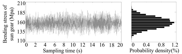
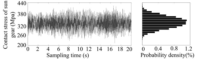
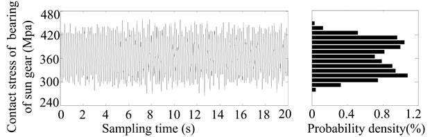
In order to obtain the stress distribution in a particular time (such as after 2, 4, 6, 8, 10, 12, 14, 16, 18 or 20 years’ operation, especially 2 years’ operation in Fig. 2), firstly, the meshing errors in certain time can be calculated by Eqs. (13)-(17). Next, according to the parameters of herringbone planetary gear reducer (see Table 1) and a load sampling obtained by the statistical distribution of load torque, the dynamic responses are derived by applying the Runge-Kutta integration method to solve the differential equations (Eq. (12)) of motion for HPGS. And then the dynamic meshing forces and radial dynamic loads of rolling bearings are derived by the relations between forces and responses. Finally, the contact and bending stresses of gears are calculated by Eqs. (16) and (17), and the contact stresses of bearings are calculated by Eq. (18). And a stress sampling and their probability density distribution of sun gear and its bearing after two years’ operation, as shown in Fig. 2.
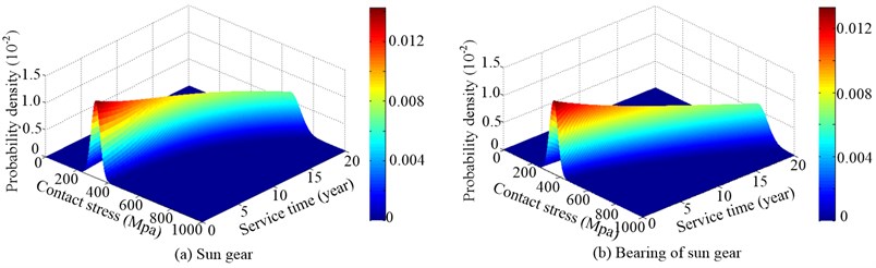
After the stress samplings and their probability density distribution of sun gear and its bearing in different operation time have been obtained by the above simulation, the probability density distribution of stress random process (Fig. 3) can be presented by the surface fitting. Fig. 3 illustrates the probability density distribution of random process of contact stress of sun gear and its bearing. As the tooth surface gradually wears over service time, and the amplitude of meshing errors gradually increases over service time, the mean value and dispersion degree (usually expressed as standard deviation) gradually increase over service time, as shown in Fig. 3. The random process of the stress in any service time follows a normal distribution, which is consistent with what is mentioned in literature [10], so it is right that the relationships are produced from the developed mathematical model.
Fig. 2Stress sampling and their probability density distribution of sun gear and its bearing
a)
b)
c)
Fig. 3Probability density distribution of random process of contact stress of sun gear and its bearing
According to material and heat treatment method of gears, the initial bending strength of sun gear, planets and ring gear respectively follow normal distributions of (580,11.62) MPa, (630,12.32) MPa, and (480,9.52) MPa, while the initial contact strength of sun gear, planets, ring gear and bearings respectively follow normal distributions of (1280,25.62) MPa, (1320,26.42) MPa, (1180,23.62) MPa, and (1520, 30.42) MPa. The strength random process of gears and bearings can be simulated by Eqs. (22) and (23), and Fig. 4 illustrates the probability density distribution of the contact strength random process of sun gear and its bearing (1, 2, 1.2×10⁷ MPa). When the fatigue damage caused by the applied load is considered, the mean value of the strength of sun gears and its bearing gradually decreases over service time, while the dispersion degree gradually increases over service time, as shown in Fig. 4.
The time-dependent reliability of gears and bearing with a single failure mode, as shown in Fig. 5, is calculated by Eq. (24). As shown in Fig. 5, when tooth surface wear and strength degradation are considered, the reliability of gears and bearings gradually decrease over service time, and the longer the service time is, the faster the reliability declines. What is more, the contact fatigue reliability of teeth of sun gear is smallest (see the curve I in Fig. 5), while the contact fatigue reliability of bearing of carrier is biggest (see the curve IX in Fig. 5).
Fig. 4Probability density distribution of the contact strength random process of sun gear and its bearing (a= 1, p= 2, C= 1.2×10⁷ MPa)
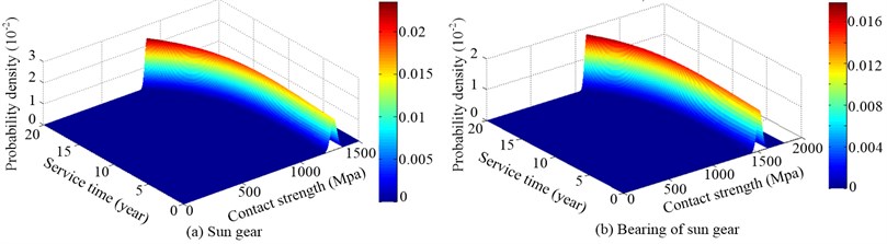
Fig. 5Time-dependent reliability of gears or bearings under a single failure mode: I-III denote the contact fatigue reliability of teeth of sun gear, planets and ring gear, respectively; IV denotes the contact fatigue reliability of bearings of planets; V-VII denote the bending fatigue reliability of teeth of sun gear, planets and ring gear, respectively; VIII and IX denote the contact fatigue reliability of bearings of sun gear and carrier respectively
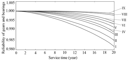
Fig. 6 illustrates time curve of the correlation coefficient between the contact fatigue failure mode of the sun gear and the other failure modes. Because of the effect of gear wear and fatigue damage on the stress and strength random process, all the correlation coefficient goes up over service time, and the longer the service time is, the faster they go up. The correlation coefficients - go up faster than the others, and this shows that the effects of gear wear and fatigue damage are more evidenton failure dependency of contact fatigue failure between teeth of sun gear, planets, ring gear, and bearings of planets. As the correlation coefficients - are bigger than (0.5), the corresponding failure modes are regarded as one failure mode group, such as contact fatigue failure of teeth of sun gear, planets and ring gear, contact fatigue failure of bearing for planets, bending fatigue failure of teeth of sun gear, planets and ring gear. Similarly, as the correlation coefficients - are smaller than (0.5), the failure modes are considered as the other failure mode group, such as contact fatigue failures of bearing of sun gear and carrier.
Fig. 6Time curve of the correlation coefficient between the contact fatigue failure mode of the sun gear and the other failure modes: the subscript 1 denotes the contact fatigue failure mode of teeth of the sun gear, the subscript 2-9, denotes in turn the contact fatigue failure of teeth of planets and ring gear, contact fatigue failure of bearings of planets, bending fatigue failure of teeth of sun gear, planets and ring gear, contact fatigue failure of bearings of sun gear and carrier
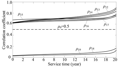
Table 2Time-dependent reliability of the herringbone planetary gear reducer
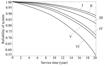 | |||
Installation of shafts for sun gear and planets in the axial direction | Failures dependency of parts | Manufacturing errors of planets | Curve |
Free | Independent | Same | I |
Different | II | ||
Dependent | Same | III | |
Different | IV | ||
Fixed | Same | V | |
Different | VI | ||
Based on the above analysis, the failure modes of HPGS are divided into two failure mode groups. The time-dependent reliability of every failure mode group is calculated by Eq. (29), and then the time-dependent reliability of HPGS is calculated by Eq. (30). Table 2 illustrates the time-dependent reliability of the herringbone planetary gear reducer in several different situations. See the curve I and II in Table 2, when assuming that the failures of the parts are independent of each other, the reliability of the gear reducer slowly declines over service time. See the curve III and IV in Table 2, when the failure dependency of the parts is considered, the reliability of the gear reducer quickly declines over service time. See the curve I and III or II and IV in Table 2, when the errors of planets are different of each other, the reliability of the gear reducer declines more significantly than that when all the errors of planets are the same. See the curve III and V or IV and VI, if the shafts of planets and sun gear is fixed in their axial direction, Partial load that is caused by the manufacturing error will make the stress and failure dependency of parts for HPGS increase significantly, thus the reliability of the gear reducer declines more significantly than that when the shafts of the planets and sun gear is free in their axial direction.
7. Conclusions
A gear-bearing dynamic model for a herringbone planetary gear set is constructed, and then the dynamic stresses of gears and bearings are derived by Runge-Kutta integration method, finally the stress random processes of gears and bearings are predicted by Monte Carlo simulation. The results show that when tooth surface wear is considered, meshing errors gradually increase over service time, so mean value and dispersion degree of dynamic stress of parts for HPGS gradually increase over service time, consequently, the reliability of parts decreases over service time.
A calculation model for strength random processes is built by the linear fatigue damage criterion and the Poisson random process that is regarded as the counting process of the deteriorating random processes of the stress, and then strength random processes are predicted when initial strength of gears and bearings is given. The results show that fatigue damage of parts under a random applied load will make mean value of strength of parts gradually decrease, while dispersion degree of it gradually increase, consequently, the reliability of parts decreases with increase of times of load action.
Assuming that the stress and strength are considered as a random process, a time-dependent reliability model for HPGS is proposed. Then, after the stress and strength random processes have been derived by the methods mentioned in this paper, the reliability of HPGS is calculated by the proposed model. The results show that the tooth surface wear and strength degradation make the reliability of HPGS significantly decline over service time; the manufacturing errors make failure dependency of parts increase, furthermore make the reliability of HPGS quickly decline over service time; If the shafts of planets and sun gear is free in their axial direction, the failure dependency of the parts caused by the manufacturing errors, will significantly decrease, so the reliability of HPGS will be significantly improved.
References
-
McNiff B. P., Musial W. D., Errichello R. Variations in Gear Fatigue Life for Different Wind Turbine Braking Strategies. Solar Energy Research Institute, Golden, USA, 1991.
-
Xinjian Z. X. Z. Analysis of gear failure in coal-mine machinery. Lubrication Engineering, Vol. 5, 2003, (in Chinese).
-
Freudenthal A. M., Garrelts J. M., Shinozuka M. The Analysis of Structural Safety. Ft. Belvoir Defense Technical Information Center OCT, 1964.
-
Bhattacharyya G. K., Johnson R. A. Estimation of reliability in a multicomponent stress-strength model. Journal of the American Statistical Association, Vol. 69, Issue 348, 1974, p. 966-970.
-
Bhattacharyya G. K., Johnson R. A. Stress-strength models for reliability: overview and recent advances. Proceedings of 26th Design of Experiments Conference, 1981, p. 531-546.
-
Nader Ebrahimi Estimation of reliability for a series stress-strength system. IEEE Transactions on Reliability, Vol. 31, Issue 2, 1982, p. 202-205.
-
Choi In-Kyeong Estimation of system reliability for redundant stress-strength model. Korean Journal of Computational and Applied Mathematics, Vol. 5, Issue 2, 1998, p. 235-242.
-
Xue J., Yang K. Upper and lower bounds of stress-strength interference reliability with random strength-degradation. IEEE Transactions on Reliability, Vol. 46, Issue 1, 1997, p. 142-145.
-
Huang W., Askin R. G. A generalized SSI reliability model considering stochastic loading and strength aging degradation. IEEE Transactions on Reliability, Vol. 53, Issue 1, 2004, p. 77-82.
-
Sun W., Chen T., Wei J. Dynamic reliability of gears in a wind turbine gearbox under the conditions of variable wind speed and small samples. Proceedings of the Institution of Mechanical Engineers, Part C: Journal of Mechanical Engineering Science, Vol. 226, Issue 12, 2012, p. 3032-3042.
-
Gao Peng, Xie Liyang Reliability analysis of parts and system considering degradation of strength. Journal of Mechanical Engineering, Vol. 46, Issue 24, 2010, p. 162-167, (in Chinese).
-
Paolo Bucci, Jason Kirschenbaum, L. Anthony Mangan, et al. Construction of event-tree/fault-tree models from a Markov approach to dynamic system reliability. Reliability Engineering and System Safety, Vol. 93, Issue 11, 2008, p. 1616-1627.
-
Salvatore Distefano, Francesco Longo, Kishor S. Trivedi Investigating dynamic reliability and availability through state-space models. Computers and Mathematics with Applications, Vol. 64, Issue 12, 2012, p. 3701-3716.
-
Chen Jian-Bing, Jie Li The extreme value distribution and dynamic reliability analysis of nonlinear structures with uncertain parameters. Structural Safety, Vol. 29, Issue 2, 2007, p. 77-93.
-
Lu Hao, Zhang Yi-Min, Huang Xian-Zhen, et al. Practical method for reliability-based robust design of typical structural system with multiple failure modes. Engineering Mechanics, Vol. 28, Issue 8, 2011, p. 226-231, (in Chinese).
-
Yuksel C., Kahraman A. Dynamic tooth loads of planetary gear sets having tooth profile wear. Mechanism and Machine Theory, Vol. 39, Issue 7, 2004, p. 695-715.
-
Kahraman A., Bajpai P., Anderson N. E. Influence of tooth profile deviations on helical gear wear. Journal of Mechanical Design, Vol. 127, Issue 4, 2005, p. 656-663.
-
Lin A. D., Kuang J. H. Dynamic interaction between contact loads and tooth wear of engaged plastic gear pairs. International Journal of Mechanical Sciences, Vol. 50, Issue 2, 2008, p. 205-213.
-
Li Shu-ting Gear contact model and loaded tooth contact analysis of a three-dimensional, thin-rimmed gear. Journal of Mechanical Design, Vol. 124, Issue 3, 2002, p. 511-517.
-
Achard J. F. Contact and rubbing of flat surface. Journal of Applied Physics, Vol. 24, Issue 8, 1953, p. 981-988.
-
Faydor L. Litvin, Alfonso Fuentes Gear Geometry and Applied Theory, Second Edition. Cambridge University Press, New York, 2004, p. 241-266.
-
Okamoto Junzo Calculation and Design of Ball Bearing. Mechanical Industry Press Beijing, 2003, (in Chinese).
About this article

The authors would like to acknowledge the support and contribution from the State Key Lab of Mechanical Transmission, Chongqing University, China. This research was funded by the National Basic Research Program of China (973 Program, Grant No. 2014CB046304) and Science and Technology Bureau of Zigong City (No. 2013J19).
