Abstract
This paper presents a systematic methodology focused on herringbone gear microgeometry modifications toward vibration reduction. The dynamic model considering the unique characteristics of aviation herringbone gear is developed to study the vibration behavior. The optimal ease-off shape can be defined as the outcome of a multi-objective optimization process, the objective functions are loaded transmission error, meshing impact excitation and root mean square (RMS) of vibration acceleration. With special attention given to computational efficiency, a novel fitness predicted genetic algorithm is developed. An application to herringbone gear are presented, the results show the proposed method can obtain optimal modifications that significantly improve the gear performance over a wide range of operating conditions. Furthermore, the reduction of the vibration also leads to a reduction of bending stresses. Finally, a test on herringbone gear is executed under various combinations of torque and speed to demonstrate the accuracy of the proposed model.
1. Introduction
Herringbone gear is a type of gear that is a side to side combination of two helical gears of opposite hands, so the side-thrust of one half is balanced by that of the other half. They have the advantage of transferring power smoothly because more than two teeth will be in mesh at any moment in time. Because of this, herringbone gears are widely used in automotive, ships, aerospace and industrial applications.
Tooth surface modifications (tooth shaving and crowning) (TSM), also known as microgeometry modifications, have become an important phase of gear design that can remarkably enhance gear performance. It is widely believed that there is strong correlation between the static loaded transmission error (LTE) and the dynamic performance of gears, the correlation of them has been clarified and described by many authors [1, 2]. Many studies have focused on the selection of optimal tooth modifications design to minimize transmission error for reducing gear vibration [3-6].
Tavakoli and Houser [3] developed an optimization algorithm to minimize any combination of harmonics of the static transmission error, with different combinations of tip and root relief. Munro et al. [4] proposed a theoretical method for determining a set of profile modifications that gives a smooth transmission error curve. Fonseca et al. [7] use the same static model of Tavakoli and Houser [3] to optimize the harmonics of the static transmission error, by means of a genetic optimization algorithm. G. Bonori et al. [8] applied genetic algorithms for optimization profile modifications of a spur gear pair in order to minimize the LTE. The LTE is estimated by means of a nonlinear finite element approach in the paper.
The analysis of the literatures shows that, this kind of optimization approaches based on the minimization of the static LTE fluctuation is strongly dependent on the torque level used during the optimization [3, 9], which means that the classical static optimizations may lead to the system having a non-optimal dynamic behavior at other work condition. Bahk and Parker [10] developed an analytical tooth profile modification (TPM) model for planetary gears, got the conclusion that peak amplitude of dynamic response is not minimized at the amount of modification that minimizes either of these LTE or static deflection measures. M. Faggioni et al. [11] developed a dynamic optimization method to suggest the best tooth profile modification (TPM) of spur gears versus vibration reduction based on the Random plus Simplex approach. The results show the dynamic optimization produces better results than the static optimization.
Most of studies focuses on TPM of spur gears at a single work condition, only one performance is selected as the optimization objective and the effect of misalignments is often neglected in the dynamic model of spur gear pair. Few works have been done on the development of a global multi-objective modification optimization approaches to determine TSM of herringbone gears, and with special attention given to computational efficiency.
The present work is a contribution toward the suggestions expressed by M. Faggioni et al. [11]. An analytical twelve-dimensional multiple-degrees-of-freedom dynamic model of herringbone gear is developed to study the dynamic behavior. Method based on load tooth contact analysis (LTCA) is used to determine the mesh stiffness and meshing impact of dynamic model, so that the geometric modifications and high contact ratio character of herringbone gear is included in the excitation calculation. Considering the time-consuming of dynamic nonlinear function evaluations, a novel fitness predicted genetic algorithm (FPGA) has been developed. Three objectives are considered in present work. The first one is the peak to peak value of LTE(PPL), the second one is impacting force (IF) amplitude, the last one is the RMS of vibration acceleration along the line of action. A multi-objective TSM optimizations of herringbone gear with two kinds of design variables including the effects of actual operating torque level are performed, the dynamic performances of optimal gears are achieved with consideration of both accuracy and efficiency. The investigation of the bending stress in the optimum gear shows the reduction of the vibration also leads to a reduction of stresses. Finally, the test results obtained from the experiment on herringbone gear can further confirm the effectiveness of the proposed method.
2. Tooth surface modification
Litvin et al. [12] presented a computer simulation program for double-crowned helical gear. The results show the double-crowned (profile crowning and longitudinal crowning) enables to provide a parabolic function of transmission errors and reduce the noise and vibration of gear drive. As investigated by Lin et al. [13], when compared with linear relief, parabolic relief has the advantage of wider operating loading range and less sensitivity to load variations and modification parameters. The present tooth profile modification (TPM) method in this work, named three parabolic modifications is based on the modification method suggested by I. G.-Perez and litvin et al. [14], (see Fig. 1).
Fig. 1Tooth shaving and crowning of pinion
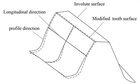
The type of topology of modified gears are based on application of two modified mismatched rack-cutters applied for the generation of the pinion and the gear respectively. With special attention given to design efficiency, only the pinion tooth surface modification is considered in this work.
Pinion rack-cutter profile is deviated from a straight line at the top, middle and bottom sides by application of three parabolic curves (see Fig. 2). The function of three parabolic curves of modified rack-cutter profile are represented as follows:
The formulation of this modification is defined by the maximum magnitude of the relief ( for the tip and for the bottom), the vertex positions of top and bottom parabolic curves are defined by magnitudes and , respectively. is the origin of the coordinates.
Fig. 2Three parabolic modification of pinion rack-cutter profile
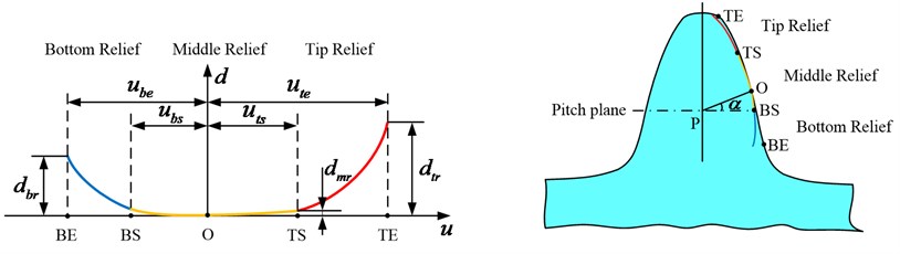
In case that 0, the middle profile of pinion rack-cutter will be based on a straight line. It is allowed to control whether the middle of the mismatched profiles is linear or parabolic before the optimization process and then remains unchanged.
In the present work, the following constraints are made for the three parabolic profile curves: (1) The three parabola profiles are smooth and continuous at the connection point, it means the first derivative of each parabola is continuous; (2) Select the reasonable maximum amount of relief and vertex positions for top and bottom parabolic curves. The parameter ranges for optimization are defined as: 0 μm 40 μm, 0 μm 40 μm.
longitudinal parabola modification along the direction of the pitch circle spiral is applied here as shown in Fig. 3.
Fig. 3The longitudinal modification of pinion
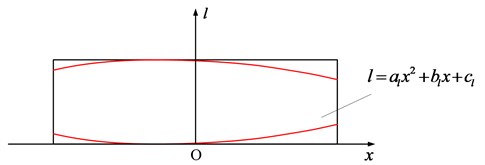
The normal longitudinal relief is defined as:
In case that 0, the longitudinal parabola modification curve is symmetrical. Details of generation of microgeometry modification is kept outside the scope of the present work, they can be identified by following the approach proposed in Ref. [15].
3. Dynamic model with tooth surface modification
Considering the unique characteristics of aviation herringbone gear, the gear is commonly fixed while the pinion is flexible in axis direction to balance the undesirable load caused by various errors. A twelve-dimensional multiple-degrees-of-freedom dynamic lumped parameter model is developed here to study the dynamic behavior of herringbone gear, with consideration of the special installation as well as the interaction between the left end helical gear and the right end one. The generalized displacement array of the system is expressed as follows:
where, and (, ; 1, 2) are the translational displacement along the -axis and -axis, while is rotational displacement at the center point . Subscripts and are referred to pinion and gear, 1 and 2 are referred to left end helical gear and right end one respectively. The vibration model is shown in Fig. 4.
Fig. 4Bending-torsional-axial coupling dynamic model
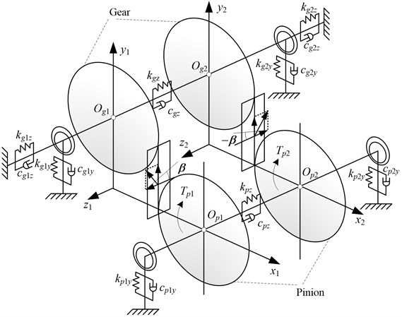
In Fig. 4, (, ; 1, 2) stand for the equivalent support stiffness of rolling bearing; are equivalent support damping; ( 1, 2) are support stiffness of gear in -axis. Subscripts , , 1 and 2 have the same meaning as described above, and stand for the -axis and -axis. and are the support tension (compression) stiffness of tool withdrawal groove in -axis, while and are the support damping.
According to the law of Newtonian mechanics, the dynamic equations of the vibration system shown in Fig. 4 can be written as the followings:
where (, ) stands for the mass of the gear, (, ; 1, 2) is the moment of inertia, is base radius, is the impact force, and ( 1, 2) stand for the meshing force along -axis and -axis respectively, and can be expressed as follows:
where, ( 1, 2) stands for the relative principal direction meshing damping [16], ( 1, 2) stands for the time-varying mesh stiffness, is axial floating displacement of pinion, is the backlash function, is the gear dynamic TE, 2 is the backlash.
The time varying mesh stiffness is one of the main excitations that causes vibration and noise of gear sets. Based on the helical gear LTCA model developed by Zhang and Fang [17, 18], a model for herringbone gear is introduced to calculate the periodically varying mesh stiffnesses. Theory of tooth contact analysis (TCA) proposed by Litvin et al. [12] provides a theoretical foundation and analysis framework for LTCA.
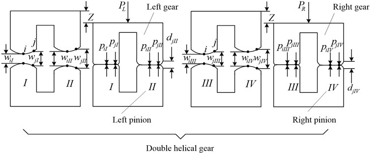
The model for LTCA of herringbone gears is illustrated in Fig. 5. Two pairs of teeth, I and II that represent the two teeth in the left end, III and IV for the teeth in the right end, are in contact at a particular instant during the meshing cycle.
When load is applied, the driving gear goes through an approach , which can be solved from the nonlinear programming problem for each contact position. It is actually the loaded transmission error (LTE) which is equal to the amount of linear displacement error of the driven gear along the line of action.
For simplicity, the contact load of the two contacting tooth surfaces is assumed to be distributed along the relative principal direction. ( I, II, III, IV) is applied to define the contact point, and is used for the point along the relative principal direction.
The state of contact after deformation can be described by the following equation for the tooth pair :
Meanwhile, the contact force must satisfy the following conditions to ensure the normal engagement:
where, , (1, 2, 3,…, ) is the contact load applied at point of the tooth pair ; , (1, 2, 3,…, ) is the tooth clearance under load at point ; is the assembled flexibility matrix determined by FEM for the contact position considering the geometric modifications of gear, tooth surface modifications(TSM) are considered in the FEM model; is the initial tooth gaps obtained from TCA. More details of LTCA are presented in Ref. [17, 18].
Once the normal contact force is determined, gear mesh stiffness can be calculated by a ratio of normal contact force and the displacement along the line of action, which includes all geometric modifications and physical aspects of the gears.
In this paper, meshing impact is the entering impact while the exiting one is ignored for simplify [19, 20]. The LTCA model aforementioned is utilized here to provides a better solution to calculate the total loaded deformation of herringbone gear with high contact ratio. The location of entering meshing impact point (EMIP) can be determined exactly. The impact force at any meshing time can be further determined. More information about formula of impact point and velocity are presented in reference [21].
Fig. 5The model for loaded tooth contact analysis of herringbone gears
4. Formulation of the fitness predicted genetic algorithm
Evolutionary algorithms, especially those based on genetic algorithms(GA), have proved quite effective in solving many optimization problems [22]. In order to get a balance between the computationally efficient and solution accuracy, an improved genetic algorithm with fitness predicted mechanisms, named fitness predicted genetic algorithm (FPGA) was developed for the solution of the optimization problem in hand. With the proposed fitness predicted mechanisms based on the concept of credibility, the algorithm can adaptively adjust the predicting time according to the predicting accuracy.
4.1. Fitness prediction model based on the credibility
For each individual in population, there are a and a corresponding credibility value . As shown in Fig. 6, specify the fitness sharing radius for individual . In the solution space, a region, the dimensionless Euclidean distance to individual is not greater than , is termed a fitness sharing region, denoted by .
Fig. 6Shared region of fitness
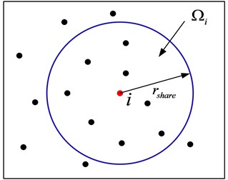
Suppose that, except individual , there are other individuals in fitness sharing region . They can be written as: .
The credibility value of individual is defined as:
where is the weighting factors that be added to measure the contribution made on credibility value . Dimensionless Euclidean distance between individuals in and individual are represented by ,,…, respectively.
Then can be obtained by:
where is the adjustable coefficient for weight factors.
Set a trust threshold , if credibility value , then predict the fitness of individual according Eq. (16); otherwise, , calculate the true fitness of individual , and set the credibility value to 1:
In order to prevent that the size of the historical population information is too big to handle efficiently, the concept of individual redundancy is introduced to determine whether the data is redundant. Once an evolution is completed, redundant data need to be removed.
The redundancy of an individual is defined as :
where represent the coordinates difference (absolute value) between the previous projection point and the later projection point of individual in the -dimensional of design space. if , is the given redundancy threshold, the individual need to be removed. In addition, with the evolution of population, the credibility values of individuals with predictive fitness should be gradually decreased. is utilized here to represent the credibility value of individual with predictive fitness in -generation, the credibility value in () – generation can be expressed as:
where is the factor of credibility loss rate, and 0 1. When an individual’s credibility value drops below the given remove threshold , it means that the fitness is no longer credible and must be removed from the historical population database.
4.2. Procedures of fitness predicted mechanisms
The main procedures of fitness predicted mechanisms are performed as follows.
S1: Initialize the population history database;
S2: For individual , define its fitness sharing region , find the set with individuals included in from the historical population database;
S3: Calculate of individual according to Eq. (14), if , then predict the fitness of individual according Eq. (16); otherwise, calculate the true fitness of individual , and set the credibility value to 1;
S4: Add the individual to the history population database;
S5: Determine whether the fitness of each individual in current population is calculated, if it is, then go S6, otherwise turn S2;
S6: Update the historical population database as follows: 1) Calculate the redundancy of all individuals, remove all redundant individuals; 2) for all individuals with predictive fitness, update its credibility according to Eq. (18), remove the individuals that are not credible.
A numerical experiment is presented in reference [23] to test the convergence and the validity of the algorithm. The advantage of FPGA is well verified by the test result.
5. Multi-objective microgeometry optimization of herringbone gear
5.1. Design variables considered
The present three parabolic modifications of pinion tooth profile are simplified that 0 for the reduction of variables. The design variables of tooth shaving are: tooth reliefs and , vertex positions of parabolic curves and (for the top and bottom). The design variables of tooth longitudinal crowning are the parabolic quadratic coefficient .
Here, two kinds of design variables are considered. The first optimization (Case A) means both the left and right end of pinion have the same modification parameters.
Consider the existing manufacturing and installation errors, the left and right ends of herringbone gears cannot mesh synchronized, so different tools can be applied for processing modification. The second optimization (Case B) means different modifications are applied for the left end helical pinion and right end one respectively.
Case A: ,
Case B: ,
Here, Subscripts 1 and 2 are referred to left end helical gear and right end one respectively.
5.2. Objective function
The herringbone gear transmission system typically operate in a wide range of torque, torques of three working conditions given for the following analysis are 621 N∙m, 828 N∙m, 1035 N∙m respectively. is the operation frequency coefficients, which means the percentage of the working time of each conditions. The values are set as 0.2 (621 N∙m), 0.5 (828 N∙m), 0.3 (1035 N∙m) respectively. In this work, three objectives are considered as follows:
where, is the discrete LTE in working condition ( 1, 2, 3). The LTEs are evaluated over three operating conditions by application of TCA and LTCA of herringbone gear:
where, (1, 2, 3) stands for the impacting force (IF) of entering meshing impact point of modified gear in working condition :
Here, is the root mean square of the vibration acceleration in working condition . For simplification, the mean value of the left and right part of herringbone gear vibration accelerations is used to evaluate the comprehensive vibration level.
To apply FPGA to the optimization of microgeometry design, it is necessary to convert the initial multi-objective optimization problem into a single-objective one. In this paper, the objective function is a summation of the three functions above expressed as follows:
where is weighting factors added for the three objects. given in present work are 0.4, 0.15, 0.45 respectively.
5.3. Constraints for the design variables
Some constraints must be satisfied during the design of optimal gear. Those constraints are regarded as the penalty constrains to ensure they are not sacrificed during optimizations.
In this case, the fitness function of FPGA will take the following form:
where is the fitness function, is the objective function, is a penalty factor. is the number of constraints, is the penalty function related to the th constraint. Fig. 7 shows the main procedure of the microgeometry modifications optimization.
5.4. Numerical optimization examples and discussion
A numerical analysis is carried out on the herringbone gear pair described in Table 1. Two different optimizations (case A and case B) are performed here. For each case, the parameters of the FPGA have been taken from literature [23] as shown in Table 2.
After performing the two optimizations (Case A and Case B), the summary values of design variables, leading to improving the three given objects, are shown in Table 3.
Fig. 7Flow chart of the microgeometry optimization
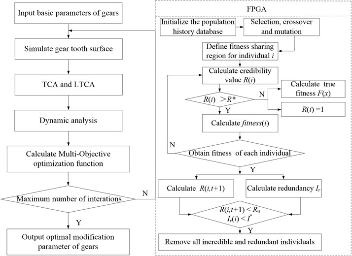
Table 1Design parameters of herringbone gear
Case study | Herringbone gear |
Number of teeth | 17 (pinion) and 44 (gear) |
Normal module (mm) | 6 |
Normal pressure angle (°) | 20 |
Helix angle on pitch cylinder (°) | 24 |
Addendum coefficient | 1.0 |
Face width (mm) | 55 |
Tool withdrawal groove width (mm) | 50 |
Shaft angle error (°) | 0.1 |
Young Modulus (MPa) | 206000 |
Poisson’s ratio | 0.3 |
Mass density (kg/dm3) | 7.85 |
Table 2Parameters of fitness predicted genetic algorithm
Items | Value |
Number of strings in the population | 50 |
Maximum number of iterations | 200 |
Crossover probability | 0.8 |
Mutation rate | 0.3 |
Trust threshold | 0.6 |
Redundancy threshold | 10-7 |
Fig. 8 and Fig. 9 show the LTE amplitude and impact force of optimized herringbone gear under a wide range of pinion torque. It can be seen that loaded transmission error amplitude and meshing impact are decreased under each working condition. In addition, the reduction is significant under the main working condition with torque of 828 N·m.
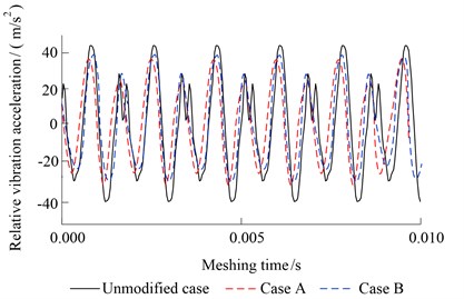
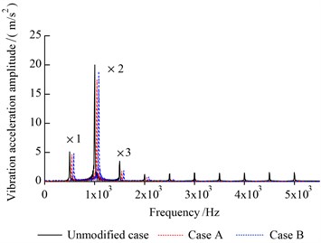
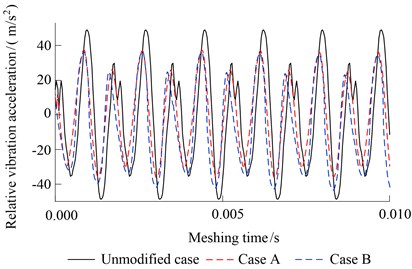
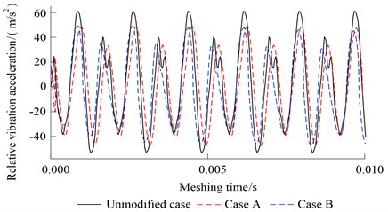
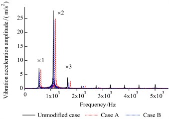
Fig. 10-Fig. 12 show the relative vibration acceleration of unmodified gears and two kinds of modified gears at the three different torques. We can see for case A and case B, the relative vibration accelerations are all decreased under the three kinds of torque. Among them, the relative vibration acceleration RMS of unmodified case under the three torques are 26.13 m/s2, 31.89 m/s2, 35.27 m/s2 respectively. For case A, they are reduced to 21.17 m/s2 (621 N·m), 23.21 m/s2 (828 N·m), 31.01 m/s2 (1035 N·m) after optimizing, the reduction is about 18.98 %, 27.22 %, 12.08 %. For case B, they are reduced to 22.43 m/s2 (621 N·m), 23.87 m/s2 (828 N·m), 30.65 m/s2 (1035N·m) of optimized herringbone gear, the reduction is 14.16 %, 25.15 %, 13.10 %. The maximum vibration reduction of case A and case B are obtained under the torques of 828 N·m which is the common use working condition.
Fig. 8LTE amplitude of herringbone gear
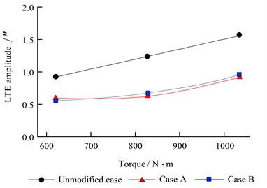
Fig. 9Meshing impact force of herringbone gear
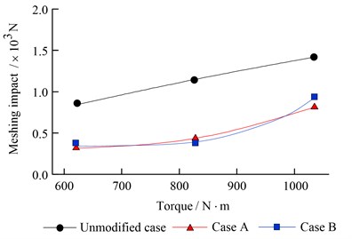
Fig. 10Relative vibration acceleration (621 N·m)
a) Time domain
b) Frequency domain
Fig. 11Relative vibration acceleration (828 N·m)
a) Time domain
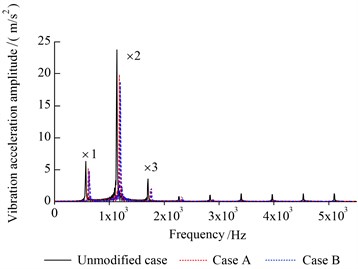
b) Frequency domain
From the analysis (Figs. 10-12), it is clear that results obtained using ten parameters optimization are similar to those obtained considering a five parameters space. Additionally, for both case A and case B, the FPGA behaves better than traditional genetic algorithm when the MOO is carried out, see Fig. 13.
Table 3Parameters of optimal modification
Case A | Case B | ||
Left /Right | Left | Right | |
Profile top relief (μm) | 14 | 13 | 13 |
Profile bottom relief (μm) | 17 | 16 | 17 |
Parabola vertex location for top crowning (mm) | 1.6 | 1.45 | 1.31 |
Parabola vertex location for bottom crowning (mm) | 3.5 | 3.8 | 3.6 |
Parabola coefficient for longitudinal relief | 1.35×10⁻⁸ | 1.03×10⁻⁸ | 1.79×10⁻⁸ |
Fig. 12Relative vibration acceleration (1035 N·m)
a) Time domain
b) Frequency domain
Fig. 13Percentage of fitness computed
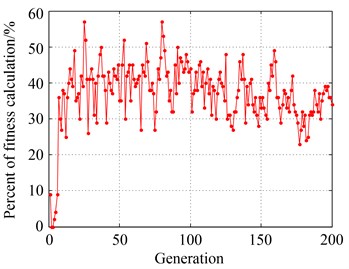
a) Case A
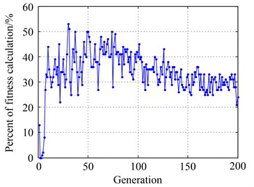
b) Case B
For case A, the percentage of fitness calculation (PFC) is about 39.67 %, it means the application of FPGA reduce the percentage of fitness calculation by 60.33 %. For case B, the PFC is about 33.25 %, the reduction percentage is 66.75 %. We can see that when dealing with this engineering problems with time consuming calculation of fitness, the use of FPGA allows to greatly reduce the computational cost and to attack higher dimensional parameter spaces. But the ten parameters optimization still requires more steps than the case of five parameters, the computational cost is reasonable but relative expensive.
Fig. 14 shows the bending stress of unmodified pinion under the three torques.
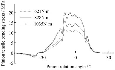
The bending stress of optimal modified pinion (case A) is shown in Fig. 15.
As shown in Fig. 15, the fluctuation amplitude of bending stress of optimal modified pinion is significantly reduced in comparison with the amplitude of gear with the unmodified tooth profile, see Fig. 14, which verifies the proper tooth surface modification can also lead to a reduction of tooth root bending dynamic stress fluctuations. This effect is more than expected.
Fig. 14The bending stress of unmodified pinion
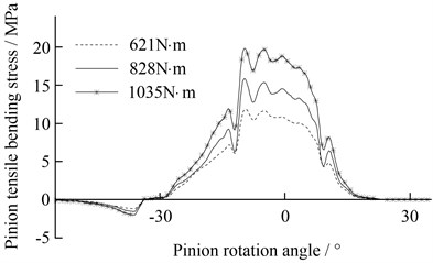
a) Left helical gear of pinion
b) Right helical gear of pinion
Fig. 15The bending stress of optimal modified pinion
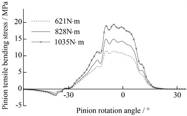
a) Left helical gear of pinion
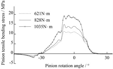
b) Right helical gear of pinion
5.5. Experiment
The test drive system of herringbone gear is shown in Fig. 16, which consists of direct current (DC) motor, reaction gearbox, torque speed sensor, five elastomer coupling, test gearbox, HEIDENHAIN radial grating, etc. The relative vibration accelerations (RVA) of gears along the line of action are measured by the HEIDENHAIN radial grating.
Fig. 16The test drive system of herringbone gear: a) the test machine; b) top view structural schematic with key components labeled
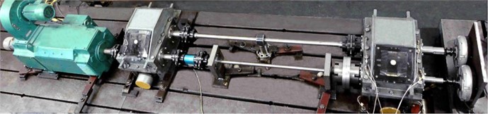
a)
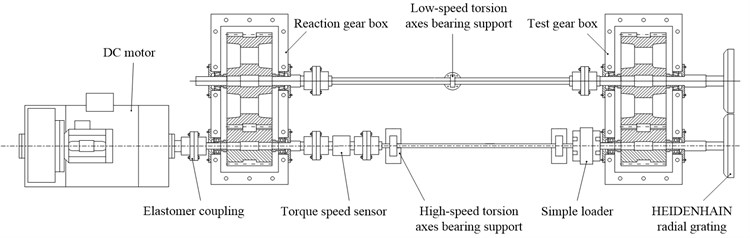
b)
Two Heidenhain radial gratings are mounted on the right end of the shafts in Fig. 16. When the system is running smoothly, acquire the angle sine analog signal of radial gratings. Then, these analog signal should be reshaped, subdivided and processed before A/D transfer. Finally, the angle analog signals are tansferred to digital signals and can be analyzed by the computer to obtain the real angle of pinion and gear. After the above procedure, we can calculate the linear displacement transmission error of gears along the line of action, the second derivative of the linear displacement transmission error is the gears vibration accelerations. The vibration accelerations are calculated as follows:
where, and are real gear angular positions, and are initial gear angular positions, and are base radius of pinion and gear.
The RMS of the vibration acceleration of unmodified gears and modified gears (Case A) under different torque (rotational speed 2000 r/min) are shown in Fig. 17.
Fig. 17RMS of the vibration acceleration
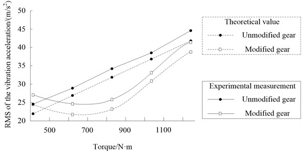
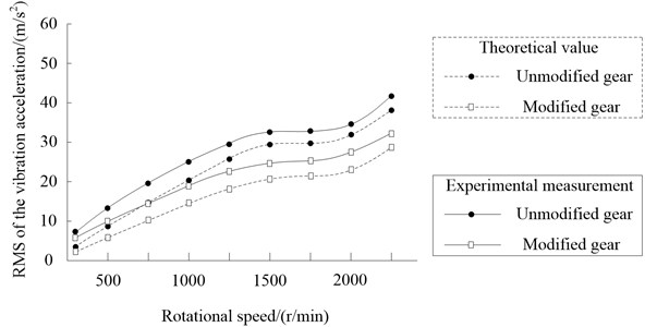
Fig. 18RMS of the vibration acceleration
The basic trend of theoretical calculation and experimental measurement are well consistent. Moreover, the maximum vibration reduction is obtained under the torques of 828 N·m, the reduction percentage of theoretical calculation and experimental measurement are 27.3 % and 24.8 % respectively. The RMS of the vibration acceleration of modified gears under 414 N·m is a little higher than that of unmodified gears.
The RMS of the vibration acceleration of unmodified gears and modified gears under different rotational speed (torque 828 N·m) are shown in Fig. 18.
The RMS of the vibration acceleration increases correspondingly with the increasing speed, and the reduction is effective over a wide range of operating rotational speed.
6. Conclusions
A global optimization method to predict the proper amount of modification of herringbone gear for vibration reduction is proposed in this paper. Tooth contact analysis(TCA) and load tooth contact analysis (LTCA) are introduced to determine mesh stiffness and meshing impact of dynamic model, so that the nonlinearity of mesh stiffness with contact force is well considered, and the effect of tooth shape deviation on mesh stiffness can also be taken into account, which offers firmly foundation for the dynamic analysis.
The optimal ease-off shape can be defined as the outcome of a multi-objective optimization process considering the requirement of various working conditions. Two numerical applications with different design variables have been performed in this work.
A comparison was made for the five parameters optimization and ten parameters optimization, the results show both the two optimizations can obtained modification parameters that significantly improve the proposed objects. The LTE amplitude, impact force and relative vibration acceleration of optimized herringbone gear are decreased under a wide range of pinion torque, especially under the main working condition with torque of 828 N·m. But the ten parameters optimization does not perform much better than five parameters optimization as expected. The objects results obtained using ten design variables are similar to those obtained considering a five parameters space. Although the application of FPGA allows to greatly reduce the percentage of fitness calculation when compared to the standard GA, the ten parameters optimization still takes much time. For this reason, the five parameter multi-objective optimization is recommended in the present case. The investigation of the bending stress shows the obtained optimal tooth surface modification also lead to a reduction of tooth root bending stress fluctuations. In addition, the test results of the experiment on herringbone gear further validate the effectiveness of the proposed method in obtaining satisfactory microgeometry solutions for gear vibration reduction.
References
-
Mark W. D. Analysis of the vibratory excitation of gear systems: basic theory. Journal of Acoustic Society of America, Vol. 63, Issue 5, 1978, p. 1409-1430.
-
Kahraman A., Singh R. Non-linear dynamics of a spur gear pair. Journal of Sound and Vibrations, Vol. 142, Issue 1, 1990, p. 49-75.
-
Tavakoli M. S., Houser D. R. Optimum profile modifications for the minimization of static transmission errors of spur gears. ASME Journal of Mechanisms, Transmissions, and Automation in Design, Vol. 108, 1986, p. 86-95.
-
Munro R. G., Yildirim N. Some measurements of static and dynamic transmission errors of spur gears. Proceedings of the International Gearing Conference, Newcastle, 1994, p. 371-376.
-
Kahraman A., Blakenship G. W. Effect of involute tip relief on dynamic response of spur gear pairs. ASME Journal of Mechanical Design, Vol. 121, Issue 2, 1999, p. 313-315.
-
Umezawa K., Houjoh H., Matsumura S., Wang S. Investigation of the dynamic behaviour of a helical gear system – dynamics of gear pairs with bias modification. Proceedings of the Fourth World Congress on Gearing and Power Transmissions, Paris, Vol. 3, 1999, p. 1981-1990.
-
Fonseca D. J., Shishoo S., Lim T. C., Chen D. S. A genetic algorithm approach to minimize transmission error of automotive spur gears sets. Applied Artificial Intelligence, Vol. 19, Issue 2, 2005, p. 153-179.
-
Bonori G., Barbieri M., Pellicano F. Optimum profile modifications of spur gears by means of genetic algorithms. Journal of Sound and Vibration, Vol. 313, 2008, p. 603-616.
-
Sato T., Umezawa K., Ishikawa J. Effects of contact ratio and profile correction of spur gears on the rotational vibrations. Bulletin of the JSME, Vol. 26, Issue 221, 1983, p. 2010-2016.
-
Bahk C. J., Parker R. G. Analytical investigation of tooth profile modification effects on planetary gear dynamic. Mechanism and Machine Theory, Vol. 70, 2013, p. 298-319.
-
Faggioni M., Samani F. S., Bertacchi G., Pellicano F. Dynamic optimization of spur gears. Mechanism and Machine Theory, Vol. 46, 2011, p. 544-557.
-
Litvin F. L., Fuentes A., Gonzalez-Perez I., Carvenali L., Kawasaki K., Handschuh R. F. Modified involute helical gears: computerized design, simulation of meshing and stress analysis. Computer Methods in Applied Mechanics and Engineering, Vol. 192, 2003, p. 3619-3655.
-
Lin H. H., Oswald F. B., Townsend D. P. Dynamic loading of spur gears with linear or parabolic tooth profile modifications. Mechanism and Machine Theory, Vol. 29, Issue 8, 1989, p. 1115-1129.
-
Gonzalez-Perez Ignacio, Litvin F. L., Hayasaka Kenichi, Yukishima Kenji Application and investigation of modified helical gears with several types of geometry. International Design Engineering Technical Conferences and Computers and Information in Engineering Conference, Las Vegas, Nevada, USA, 2007.
-
Litvin F. L., Fuentes A. Gear Geometry and Applied Theory. 2nd Edition, Cambridge University Press, New York (USA), 2004.
-
Amabili M., Rivola A. Dynamic analysis of spur gear pairs: steady-state response and stability of the SDOF model with time-varying meshing damping. Mechanical Systems and Signal Processing, Vol. 11, Issue 3, 1997, p. 375-390.
-
Zhang Y., Fang Z. Analysis of transmission errors under load of helical gears with modified tooth surfaces. ASME Journal of Mechanical Design, Vol. 119, Issue 3, 1997, p. 120-126.
-
Zhang Y., Fang Z. Analysis of tooth contact and load distribution of helical gears with crossed axes. Mechanism and Machine Theory, Vol. 34, Issue 1, 1999, p. 41-57.
-
Seireg A., Houser D. R. Evaluation of dynamic factors for spur and helical gears. Engineering for Industry. Journal of Manufacturing Science and Engineering, Vol. 92, Issue 2, 1970, p. 504-514.
-
Zhou C. J., Zhang C., Tang J. Y. Modeling and calculation of impact of mesh-out at corner contact in gear drive. Journal of Aerospace Power, Vol. 29, Issue 5, 2014, p. 1205-1210.
-
Wang F. Dynamic Characteristics Research and Experimental Study on Herringbone Gear Drive System. Northwestern Polytechnical University, Xi’An, 2014.
-
Artoni A., Gabiccini M., Guiggiani M., Kahraman A. Multi-objective ease-off optimization of hypoid gears for their efficiency, noise, and durability performances. ASME Journal of Mechanical Design, Vol. 133, 2011, p. 121007.
-
Zhao N., Zhao Y. Z., Fu C. X. Genetic algorithm with fitness approximate mechanism. Journal of National University of Defense Technology, Vol. 36, Issue 3, 2014, p. 117-129.
Cited by
About this article

