Abstract
In a pair of actual gears alternating meshing process, the transmission system errors and thermal elastic deformation of the gear teeth can cause gears in the meshing zone to form high contact pairs inconsistently mesh-in and mesh-out points to deviate from the theoretical line, which will lead to sudden changes in meshing velocity and an instantaneous meshing effect. Offline meshing impact generates large additional loads, and it increases the vibration and noise of gear transmission system. Further, the gear teeth mesh-in impact is significantly greater than that of gear teeth mesh out. Therefore, to analyze the impact with the minimum value of gear teeth mesh in, the initial mesh-in points need to be determined, and the meshing impact velocity and impact force of teeth meshing-out need to be calculated. The optimized meshing tooth-pair contact interface (CI) anti-impact numerical calculation mode is validated using the loaded teeth contact analysis method.
Highlights
- The impact dynamics mechanism of gear initial alternating intermeshing is elaborated.
- The impact effect of gear teeth meshing-in is significantly greater than that of meshing-out is further indicated.
- The gear teeth meshing-in impact with the minimum value is optimized and analyzed.
- The velocity analysis model during the impact of teeth meshing-in is proposed and validated.
- The initial meshing points are determined, and gear teeth meshing impact velocity/force are calculated.
- In-depth study of the complex mechanism of gear teeth modification with the minimum value of meshing impact has practical guiding significance.
1. Introduction
Gears with teeth meshing are subject to mild to considerably severe meshing effects that depend on the extent and distribution of the gear transmission errors. Meshing outside the normal path of the gear teeth may lead to meshing impact because of the sudden fluctuation in rotation velocity [1-3]. Further, the meshing impact may induce dynamic load, vibration, and noise. Even if a meshing gear in the time domain has an accurate involute tooth profile under working conditions, the gear teeth will change the base joints of the driving and driven gears to the position of the meshing line. This is attributed to the deformation of the gear tooth load and the installation error under the initial action of the meshing force which is no longer equal, and therefore, it causes gear tooth surface interference that deviates the meshing point from the normal meshing line [4-6].
Three types of meshing impacts-mesh-in, mesh-out, and node-have been observed in gear transmission systems [7-9]. Node impact has the lowest effect, followed by mesh-out impact and then by mesh-in impact. Thus, gear transmission errors are considered to analyze the meshing impact [10-12].
The meshing impact is derived based on the mesh-in impact velocity model; simulation results of some typical examples with the meshing impact on gear pairs are utilized to validate the model [13-15]. Loaded teeth contact analysis (LTCA) is an important numerical method that simulates the teeth meshing pattern under loaded conditions [16-18]. An optimum teeth surface modification design can be developed by combining LTCA and teeth modification and by studying loaded teeth meshing under modifications [19-21]. Modifications to the addendum and dedendum can effectively improve teeth meshing performance, decrease meshing impact and noise, and increase loading capacity because it helps achieve uniform load distribution on the teeth surface [22-24].
Modified parameters can be obtained by applying the complex method [25-27] to minimize the meshing impact and uniformly distribute teeth surface load. Subsequently, several typical examples were utilized to verify the correctness of this modification method via comparison of the loaded transmission error, maximum impact force, and load distribution factor before and after modification [28-30].
The time-domain transmission error and gear tooth deformation in the working condition causes the normal joint of the meshing gear pair to be unequal and deviate from the theoretical meshing line at the mesh-in and mesh-out points, which results in a transient meshing impact because of the abrupt changes in rotational speed. The out-of-line meshing impact generates a large additional load, and it increases the vibration and noise of the gear transmission system, thereby affecting the comprehensive performance of the gear transmission system.
This article focuses on mesh-in impact; the initial mesh-in point position is determined and the initial mesh-in impact velocity and force are calculated to evaluate the mesh-in impact.
2. Mechanism of mesh-in impact and calculation model
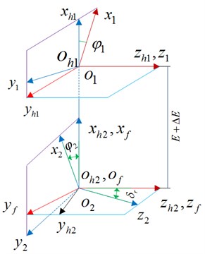
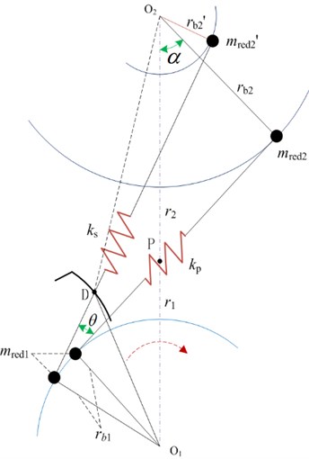
The contact process between the edges of two gear teeth is called the interface edge contact. In this study, the tangent at the contact point along the toothed edge of the driving gear is assumed perpendicular to the normal at the contact point of the teeth surface of the driven gear. Further, the study considers the edge contact of the helical gear (including the teeth-side and teeth tip edge contacts) as the carrier object during the mesh-in to the mesh-out period. The coordinate relationship for a pair of gears that mesh is shown in Fig. 1.
Fig. 1Coordinate relationship of a pair of gears
Setting 1 represents the pinion teeth-side edge contact; parameter is constant. The expression of the contact equation of the teeth surface interface is given as:
Setting 2 represents the pinion top-edge contact; the parameter is constant. The contact equation of the teeth surface interface is expressed as:
where, given parameter , the other four unknown parameters can be solved to determine the contact point. expresses the conversion matrix of each vector in the fixed coordinate system, represents the rotation sub-matrix, is the component of theoretical teeth surface position vector, is expressed as an input variable, where the subscripts 1 and 2 represent the driving gear and driven gear, respectively. For each instantaneous contact point, the corresponding main curvature and direction can be determined separately; thus, the meshing imprint can be determined.
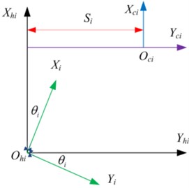
Fig. 2Coordinate relationship between normal teeth profile and extended teeth surface
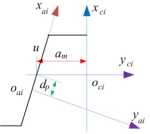
a)
b)
Fig. 2 shows the coordinate relationship between the normal teeth profile of the rack-shaped cutter and the rack used to form a tooth surface. The related expressions of the theoretical teeth surface position vector and normal vector are given as:
where ( represent small and large gears, respectively) is the parabolic equation in the tooth profile coordinate system and is the interface parameter of the teeth surface on the section of the rack cutter; the distance from the point on the teeth profile to the parabolic pole is described. Further, denotes a tooth surface interface parameter and indicates the distance of the normal section where the points on the teeth profile are located from the coordinate origin ; is the position parameter of the parabolic pole; and are the pressure and spiral angles, respectively; and is the normal half-tooth thickness on the rack pitch line. Thus, the unit normal of the tooth surface interface can be determined as:
The tooth surface is depicted in the gear coordinate system where is the transformation matrix from the coordinate system to ; it is depicted as:
where is the rotator matrix:
Eq. (6) must be met when machining the teeth surface enveloping the gear interface, where is the relative velocity of the tool and the gear being machined.
Considering the various operating conditions, the transmission error of gear pair is defined as the value of the actual rotation angle of the driving gear that deviates from the theoretical rotation angle with the change of the rotation angle of the driven gear expressed as:
where is the initial angle of the pinion, is the initial angle of the large gear, and and represent the number of the teeth of the pinion and large gear, respectively.
Fig. 3Theoretical teeth surfaces of helical gear with rack spread
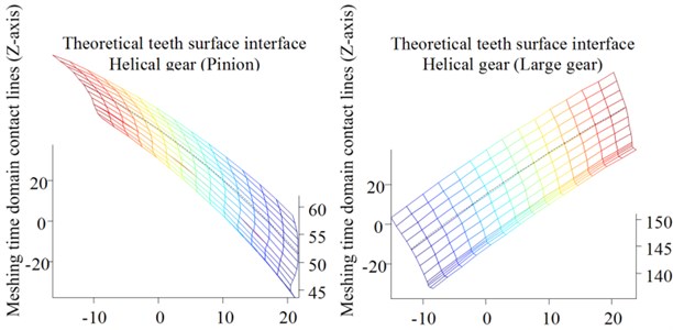
The actual tooth surface of the helical gear is different from its theoretical tooth surface when considering manufacturing errors; a smooth surface is formed after a certain time of running-in. Theoretical teeth surfaces (pinion and large gear) of a helical gear with a rack spread are shown in Fig. 3. The precision requirement of a tooth surface less than 1.0 μm is often difficult to achieve using NURBS that fits the sampled three-coordinate data directly. Teeth surface errors are obtained through three coordinate measurements, and the actual teeth surface are constructed by the superposition of the theoretical teeth surface and the normal error surface. Based on the gear teeth errors and elastic deformation of the bearing gear, the time domain meshing gear produces a “meshing synthetic base node error” that causes the pair of gear teeth to deviate from the theoretical mesh-in point on the meshing line when entering the initial mesh-in; then, it causes the mesh-in impact. This appearance mechanism is the focus of the research group and the next step to study the problem.
2.1. Mechanism of mesh-in impact considering CI thermoelastic expansion behavior
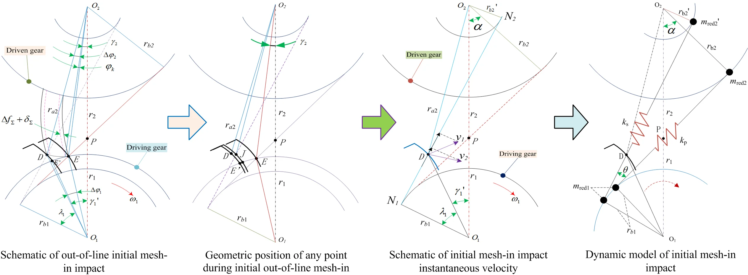
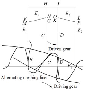
In gear transmission system dynamics, the effect caused by the meshing synthetic base node error is called referred to as the mesh-in and mesh-out impact of the gear teeth surface meshing process. For this study, the core objective is revealing the mechanism of the initial mesh-in impact. Considering the equivalent error of the system and the comprehensive deformation of the gear teeth, the exact position of the initial mesh-in point out-of-line is calculated based on the meshing principle and geometric relationship shown in Figs. 4 and 5, respectively.
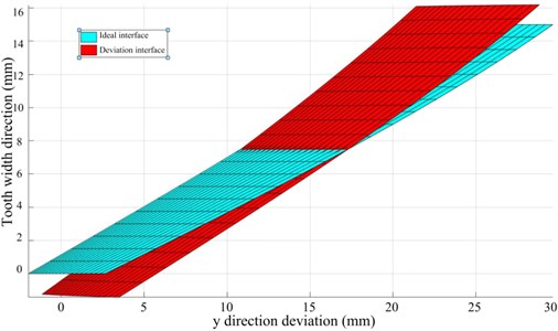
The actual tooth surface becomes a smooth surface after running-in. The sampled coordinate data is directly fitted to the actual tooth surface through the NURBS surface [31]. It is often difficult to meet the high-precision requirements. Moreover, when the digital tooth surface is subjected to TCA analysis, it needs to be aligned and installed, and iteratively too many, the calculation efficiency is low, because the actual tooth surface can no longer be expressed by the theoretical tooth surface equation, and cannot be separated from the theoretical tooth surface, so the actual tooth surface can be expressed indirectly through the superposition of the theoretical tooth surface and the normal deviation surface. As shown in Figs. 6-7, the blue is the ideal tooth surface, and the red is the tooth surface with the inclination deviation of the spiral line, which defines the rotation of the inclination deviation. The direction is the forward direction.
Fig. 4Schematic of out-of-line initial mesh-in impact
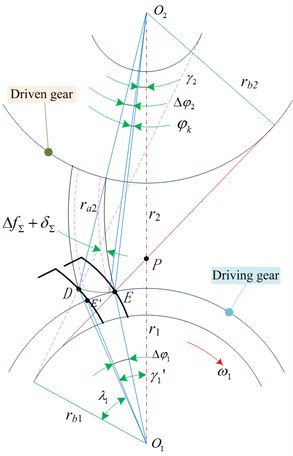
Fig. 5Geometric position of any point during initial out-of-line mesh-in
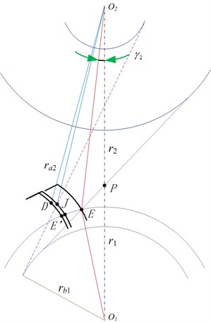
Fig. 6CI model with inclination deviation
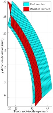
Fig. 7CI model with helix tilt deviation
The gear system transmits power and the meshing teeth bear load. The thermoelastic deformation (TED) of teeth surface causes the distortion of the teeth profile and teeth direction, resulting in impact, vibration and unbalanced load in the process of alternate meshing. Based on the mechanism of teeth profile modification and teeth alignment modification of involute gear, the time-varying law of TED of alternate meshing contact interface with meshing position is considered, the distribution coefficient of transient contact dynamic load is shown in Fig. 8.
Fig. 8Transient contact dynamic load distribution coefficient of gear pair in alternating meshing process with maximum profile modification
The maximum value of contact dynamic load on the teeth during the alternate meshing process of gear pair is placed in the meshing in and meshing out transients in the single teeth meshing area, which are also shown in the Fig. 8 and , the initial point of the gear teeth is deformed greatly points and endings , the reason of the meshing is the interference process of gears , the point is caused by the maximum transient contact dynamic load , if the point meshing interference occurs, the top of the driving gear (the position where the gear teeth are engaged) must be modified, and the maximum modification amount is set to be , point maximum transient contact dynamic load leads to point , in case of meshing interference, the top of driven gear teeth (teeth engagement position) must be modified, and the maximum modification amount is , considering the influence of gear comprehensive error (base pitch error, teeth profile error, etc.) on the transmission system, the teeth profile modification amount of meshing-in and meshing-out position is taken into account and :
where, is the TED at point of the driving gear, is the TED of the driven gear at point , is the TED at point of the driving gear, is the TED at point of the driven gear, is the pitch error caused by the comprehensive error of the gear, which is selected as positive or negative according to its direction.
Taking into account the modification of involute teeth profile in the alternate meshing area of double teeth, the ideal modification curve is the change law of the modification amount increasing to the maximum value. The calculation formula of the modification curve is expressed as follows:
where, is the maximum modification amount of gear teeth, is the distance between the critical point of alternating meshing area of single and double teeth, and is also the distance from any position on the segment to point , is the length from the critical point of single and double teeth contact area on the alternate meshing line to the starting point or end point of meshing, is the contact load change index between the pair of meshing teeth, and its value is in the range of 1.0-2.0, in order to reduce the sudden change of contact load and the alternating meshing gear interface impact.
Gear parameters and teeth profile shape are affected by load distribution and contact pressure distribution between teeth and relative sliding of contact teeth to meshing teeth surface. Proper amount of addendum trimming along normal direction of driving and driven gear profile improves load contact pressure distribution between teeth, reduces relative sliding of meshing teeth surface, and optimizes contact temperature of teeth surface [11]. Taking into account the thermoelastic properties of teeth surface (teeth contact deformation and bending deformation, shear deformation and teeth root deformation, etc.), and considering the distribution of instantaneous contact dynamic load (teeth meshing stiffness) and the time-varying law of teeth contact dynamic stress and teeth root bending dynamic stress, the inaccurate calculation formula of the modified curve is as follows:
where is the TED of the teeth profile, is the instantaneous contact dynamic load per unit teeth width (N/mm), , is the tangential force on the dividing circle of the gear (), and is the meshing stiffness (N/(mm⋅μm)).
The structural contact analysis units should be rebuilt after conversion into thermal structure by the use of the model [32]. Selection of the structural units’ nodes is done with respect to the same as temperature field elements’ nodes. It enabled to define structural material properties and add thermal expansion coefficients in this analysis. The thermal expansion stiffness coefficient of the driving gear was considered to evaluate the performance of gears teeth surface coupling. The range for the rotation angle was from 0 to 35°. Selected values of the angle were employed to follow the gears behavior at 16 meshing positions. The parameters of spur gears are listed in Table 1.
Table 1The parameters of spur gear pairs
Teeth number driving gear | Teeth number driven gear | Pressure angle | Modulus (mm) |
33 | 151 | 20 | 9.5 |
Tooth width (mm) | Power(kw) | Input speed (rpm) | Initial oil temperature |
330 | 1500 | 2900 | 65 |
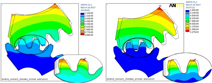
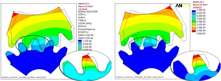
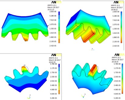
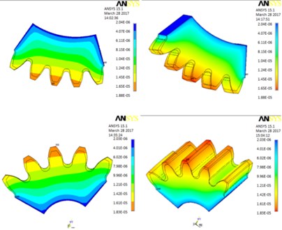
The values of contact thermal stress of the double teeth surfaces meshing coupled were increasing rapidly and achieved the alternating meshing steady state of mutual conversion. In the initial stage of gears meshed in. The thermal stress values at position 1 were greater than for the other cases considered. Therefore, the influence of meshed during impact at the position 1 for the thermo mechanical coupled contact is most obvious in Fig. 9(a).
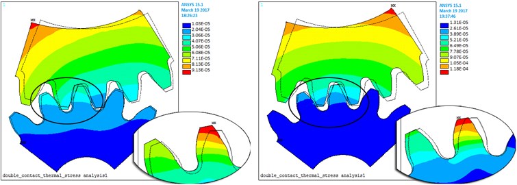
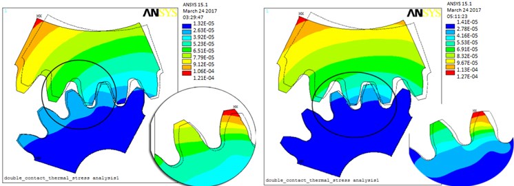
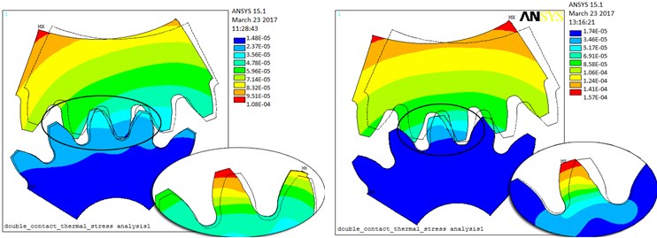
Fig. 9a) Position 1 meshed-in impact point, rotation angle is 1, b) position 2 double tooth meshing transition to single tooth C point, c) position 3 single tooth meshing area, rotation angle is 18.5, d) position 4 single tooth meshing transition to double teeth D point, e) position 5 meshed-out impact point, rotation angle is 35
a)
b)
c)
d)
e)
The elastic deformation and damping coefficients of the gears meshing conversion progress of double teeth to single tooth are considered in Fig. 9(b). The values of contact thermal stress of the alternating meshing steady state of mutual conversion are presented. These magnitudes values at position 2 were smaller than for another one.
The values of contact thermal stress of the single tooth meshing steady state are analyzed. The results at position 3 were bigger than the values for position 2. As shown in Fig. 9(c).
The values of contact thermal stress of the double teeth and above alternating meshing area are presented in Fig. 9(d). The data position 3 reached higher values than for the position 4. However, the effect of TED of the position 4 is more prominent.
As shown in Fig. 9(e), the values of contact thermal stress of the position 5 are greater than it was noticed for the 2 and 4 positions. The effect of TED of the position 4 is also more prominent.
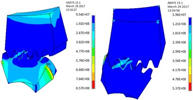
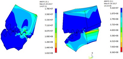
Fig. 10a), b) TED and elastic contact stress, c) driven gear thermal expansion deformation, d) driving gear thermal expansion elastic deformation
a)
b)
c)
d)
Meshed-in and meshed-in impacts and thermal expansion deformations are modern approach for the problem considered. For the key point , where the meshing area of single tooth converts into that of double teeth and above, this position is analyzed in detail in the following manner. As illustrated in Fig. 10, the value of thermal contact stress changes significantly and has the maximum amount value of 761.6 MPa.
When the single tooth is just converted into the double teeth meshing, the calculation of thermal expansion deformation of driven gear is proposed Fig. 10(a). When a pair of single teeth is ready to end the meshed-out, the calculation of thermal expansion elastic deformation of driving gear creates Fig. 10(b). It is more clearly seen on Fig. 10(c) and Fig. 10(d), the thermal expansion elastic deformation is enlarged along the tooth height values and reached maximum value of 51.3 μm.
When the gear teeth are affected by load deformation, a system error generates offline meshing. This can lead to a contact-teeth relative velocity difference where the actual meshing point is along the teeth profile normal line direction. The mesh-in impact instantaneous velocity is shown in Fig. 11. The deformation of the gear tooth and system error cause out-of-line meshing, which leads to a relative velocity difference of the contact tooth pair along the common normal direction of the tooth profile at the actual mesh-in point.
For and :
where represents the center distance between two gears, is the radius of the tooth top circle of the driven gear, and is the pitch circle radius of the driven gear; is the base circle radius of the driving gear; and is the pressure angle of the index circle.
The circumferential velocity and of the gear pair at the point are decomposed into two components (, ) and (, ) along the instantaneous meshing line and its perpendicular line, respectively. The velocity of the two teeth profiles along the direction () of the instantaneous meshing line at point can be obtained from the geometric relationship. In practice, the meshing process of the mesh-in impact mechanism occurs as follows: the driven gear engages in advance from point and the mesh-in impact occurs; then, the driven gear scratches along the flank of the driving gear until the gears mesh along the line of action.
Fig. 11Schematic of initial mesh-in impact instantaneous velocity
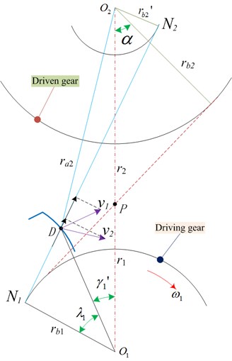
Fig. 12Dynamic model of initial mesh-in impact
2.2. Calculation model of initial mesh-in impact considering manufacturing errors
In heavy-duty and high-line speed gear transmission systems, the main effect of the load distribution coefficient and dynamic impact force is the load transmission error. Based on the mechanism of mesh-in impact, the main sources are the load distribution coefficient and meshing impact. Further, the load distribution coefficient originates from the manufacturing and pitch error, and the meshing impact is caused by the assembling error and normal backlash. The effect of the meshing impact is larger than that of the uneven load distribution, and therefore, the minimum value of the meshing impact is considered in this study.
Modification involving the clockwise diagonal trimming and teeth profile is considered. The load distribution coefficient and meshing impact are random variables, and they follow a standard normal distribution. The effects of meshing impact value, load distribution coefficient, and optimized modification on the transmission precision and load-carrying properties are associated with each other. The contact teeth relative velocity difference where the actual meshing point is along the teeth profile normal line direction, i.e., the mesh-in impact instantaneous velocity and relative velocity along the common tangent direction are given as:
where and are the mesh-in impact real-time velocity of driving gear (active gear) and driven gear (passive gear), respectively; further, and are the angular velocities of the driving and driven gears, respectively.
The mesh-in impact velocity and impact force are always present from the beginning to the end, when a pair of gears are intermeshing alternately along the normal contact path. The load distribution coefficient is defined as the ratio of the tangential impulse and normal impulse, and it is obtained and approved with the presented reference. Considering gear teeth elasticity and its own mass and inertia, out-of-line meshing leads to an increase in impact velocity, and the impact is inevitable at the meshing point . The magnitude and variation in the meshing impact force are closely related to the impact velocity, gear teeth meshing stiffness, and load. The mesh-in impact transient dynamics model is shown in Fig. 12. The moment of inertia of the two meshing gears is transformed into the induced mass of the unit teeth width on the instantaneous meshing line as:
where is the moment of inertia of the driving gear, is the moment of inertia of the driven gear, is the induced mass of unit tooth width on the instantaneous meshing line of the driving gear, and is the induced mass of the unit tooth width on the instantaneous meshing line of the driven gear; is the instantaneous base circle radius corresponding to the instantaneous meshing line of the driving gear and is the instantaneous base circle radius corresponding to the instantaneous meshing line of the driven gear; is density; and is inner hole radius of gear hub.
The impact force is closely related to mesh-in impact velocity, impact duration, mesh stiffness, and load. The impact kinetic energy is given as:
The maximum impact force is:
According to the impact mechanics theory, the maximum deformation and maximum impact force relative to energy is equated as:
where the impact kinetic energy of the meshing gear is, is the maximum deformation, and is the maximum impact force. Further, is the comprehensive performance of the mesh-in impact meshing point (not including Hertz contact), is the teeth surface width, and is the radius of the internal cycle of the gear, ; further, and are the base cycle radii of the driving and driven gears, respectively.
The optimization of modified teeth surface is an iterative process of solving nonlinear contact problem, which is also called the process of changing the state of modified teeth surface to improve the contact condition of gear meshing surface. Set the gear pair modification optimization variable as its curve parameter, the LTCA numerical analysis result is the optimization objective function. This topic is based on genetic algorithms (GA) to simulate the genetic and evolutionary processes of organisms in the natural environment, and then searches for adaptive global optimization probabilities, reproduces and optimizes populations and converges to the most suitable environmental individuals. The GA process is shown in Fig. 13, and its steps can be described. Step 1. Select the objective function and determine the variable domain and coding accuracy to form the code. Step 2. Perform crossover operations on individuals selected to enter the matching pool to form a new population. Step 3. Select population individuals with a small probability to perform mutation operations to form a new population. Step4. Calculate individual fitness based on fitness function and select probability to form a new population of individuals. Step 5. If the check conditions are met, the GA ends, and the individual with the highest current population fitness is the expected solution.
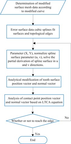
Considering that the B-spline surface uses non-parametric implicit representation of the smooth connection of multiple surfaces, the relationship between variables in the defined domain is described. If the slope of a point in the point set tends to be parallel to the axis of coordinates, the slope at this point is close to infinity. In view of the fact that curves and surfaces in a non-identical plane are mathematically expressed by parametric equation. In the LTCA equation, the parameter , , , , , the gear parameter , the tool parameter , the gear parameter and the tool parameter are mapped to the point on the rotating projection surface, and then the space is mapped to the spline surface parameter space , the three-coordinate modified surface mesh data are all within the actual teeth surface. With the help of Matlab to solve the nonlinear equations, the iterative analysis gear parameter and tool parameter exceed the boundary of the teeth surface, and the modified surface must be extrapolated. Based on the data of the rectangular grid, the control vertices are inversely calculated and kept unchanged. The four boundaries of the space rectangular grid are naturally extended to the left and right boundaries of the teeth tip, teeth root, and teeth side, and then mapped to the parameter space domain of the spline surface. The optimization analysis process of LTCA for tooth surface modification is shown in Fig. 14.
In gear transmission, when the load transmission error is constant, the gear does not vibrate. The goal of shape modification is to try to control the amount of change in operation to a minimum [33]. Gear pairs usually work under multiple working conditions, for which the objective function is expressed as the smallest fluctuation of the transmission error amplitude within a certain load range. This topic analyzes the transmission process of gear system vibration to box vibration: the dynamic load of the gear system vibration of cylindrical gears (straight teeth, helical teeth, herringbone teeth) is distributed from the meshing part of the gear pair to the inner ring of the supporting bearing at both ends through the transmission shaft, which is transmitted to the inner wall of the bearing hole of the box body, and then stimulates the vibration response of the box body. Since geometric transmission error (inter-tooth gap) and tooth surface normal gap are important factors that affect the actual coincidence of gear teeth, for involute cylindrical gears, since they are in line contact with the tooth surface, the size of the geometric transmission shape error is relative to the gear teeth. The bearing transmission error has a greater impact, especially for gear pairs with a high degree of coincidence. In order to more effectively reduce the gear tooth load transmission error, it is necessary to change the instantaneous contact gap (inter-tooth gap and normal gap), and the change of the inter-tooth gap requires the design of the high-order geometric transmission error tooth surface, the normal gap The change requires changing the size of the major axis of the contact ellipse.
Fig. 13Heavy-duty/high-line speed transmission system gear pair mesh-in impact optimization
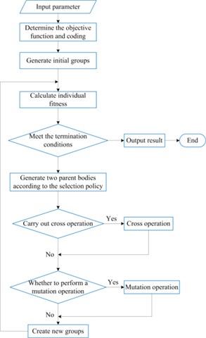
Fig. 14Analytical LTCA optimization of modified CI
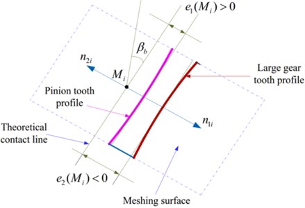
There will inevitably be errors in the machining and installation of gears, which will cause the tooth profile to deviate from the theoretical position [34]. Due to the time-varying error, this deviation forms a displacement-type excitation in the gear meshing process. In the study of the dynamic characteristics of gears, the manufacturing error of gears can essentially be regarded as the displacement-type excitation of gear tooth meshing caused by the deviation of the tooth profile surface from the ideal tooth profile. The deviation of the actual tooth profile from the ideal tooth profile is regarded as a combination of two types of offsets, the first type of offset is the base pitch error , and the second type of offset is the tooth profile error . These two kinds of errors are measured in the normal direction of the ideal tooth profile, and the positive direction is consistent with the error direction caused by the tooth deformation. When studying the dynamic excitation of manufacturing error, the specific accuracy measurement error in the gear accuracy standard is often bypassed, and the offset of the actual tooth profile surface relative to the ideal tooth profile surface is directly defined. The various errors of gears affect the gear transmission performance through the form of meshing line increments, and the base pitch error and tooth profile error are just the direct forms of meshing line increments. Fig 15 shows the manufacturing error of the gear pair at a point on the meshing plane. From the figure, the manufacturing error of the gear pair at point on a pair of meshing gear teeth is:
where, is the manufacturing error of pinion, including base pitch error and tooth profile error, is the manufacturing error of large gear, including base pitch error and tooth profile error.
Fig. 15Manufacturing error of gear pair at point Mi of meshing surface
When analyzing the dynamic characteristics of gears, generally the above-mentioned errors are projected along the meshing line to obtain the meshing comprehensive error, and this comprehensive error is used to express the static transmission error of the gear transmission. The variation law of the error is expressed in the form of Fourier series, the fundamental frequency is the meshing frequency, and then the static transmission error of each meshing pair in the second stage is:
where, is the comprehensive transmission error amplitude of sun gear-star gear meshing, is the comprehensive transmission error amplitude of sun gear- planetary gear meshing, is the comprehensive transmission error amplitude of internal gear ring-star gear meshing, is the comprehensive transmission error amplitude of internal gear ring- planetary gear meshing, is the meshing frequency of the star gear train, is the meshing frequency of the PGT, is the order phase difference of the meshing error between the sun gear and the star gear, is the order phase difference of the meshing error between the sun gear and the planetary gear, is the order phase difference of the meshing error between the internal gear ring-star gear, is the order phase difference of the meshing error between the internal gear ring-planetary gear, is the initial phase of order of the , is the initial phase of order of the , is the initial phase of order of the , is the initial phase of order of the , is the initial phase of order of the and , is the initial phase of order of the and . In this chapter, the influence of meshing composite error excitation on the amplitude-frequency characteristics of the system is considered, and the amplitude-frequency characteristic curve of the system is obtained.
3. Example verification and analysis
3.1. Optimization analysis for herringbone gear
A principal method is used to modify the gear for improve meshing performance. The modification is not considered and the gear and pinion are installed right. Further, the deformations of the shaft, bearing, and gearbox are not considered. The no-load teeth surface imprinting and geometric transmission errors are shown in Fig. 16; the bar graph of the mesh-in impact load for the herringbone gear is shown in Fig. 17; the load distribution curve of the herringbone gear is shown in Fig. 18; and the optimized clockwise diagonal modification curve and surface is shown in Fig. 19. The herringbone gear parameters and material parameters used in this study are listed in Table 2. The material grade of the gear studied in this subject is 17CrNiMo6 carburized steel, the elastic modulus (E) is 206 GPa, the Poisson’s ratio (Nu) is 0.25-0.30, and the high-pair friction coefficient () is 0.10-0.12 under TEL conditions. Low carbon alloy steel is carburized and quenched, the core strength after carburizing and quenching is 1100-1300 MN/m2, and the impact toughness is 80-100 J/cm2.
Table 2Parameters of herringbone gear pairs
Gear geometric parameter | Pinion gear | Large gear |
Normal modulus (mm) | 8 | 8 |
Tooth number | 17 | 44 |
Tooth width (mm) | 168 | 168 |
Shaft length(mm) | 300 | 300 |
Shaft radius (mm) | 45 | 55 |
pressure angle | 20 | 20 |
Helix angle (°) | 24.45 | 24.45 |
Weight (kg) | 17.8 | 101.2 |
Moment of inertia (kg⋅m2) | 0.0157 | 0.586 |
Density (kg/m3) | 7850 | |
Damping ratio coefficient | 0.10 | |
Fig. 16No-load teeth surface imprinting and geometric transmission errors

Fig. 17Bar graph of meshing-in impact load of herringbone gear
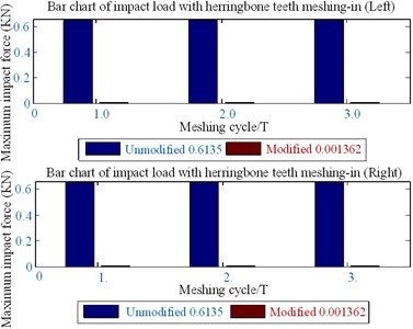
Fig. 18Load distribution curve of herringbone gear
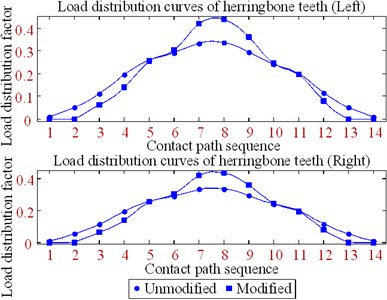
Fig. 19Optimized clockwise diagonal modification curve and surface
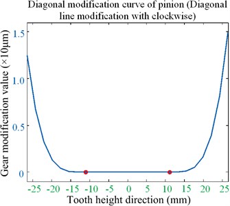
a) Modification curve
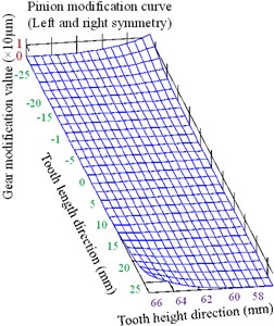
b) Modification surface
The following contributions can be drawn from the optimized results of the clockwise diagonal modification method shown in Figs. 16-19 and in Table 2.
(1) The gear meshing impact combined with the mesh-in impact velocity model is proposed to analyze the teeth surface optimized modification. The gear meshing impact is synthesized using a no-load motion error, load distribution coefficient, and the maximum impact force in the actual meshing point along the normal line of action of the teeth profile.
(2) The desired results are obtained by optimizing the modification. That is, the minimum value of the meshing-in impact is reduced by 97 %.
(3) In the process of modification optimization analysis, there is no edge contact with engagement by the gear teeth clockwise diagonal modification. It appears as the most interesting fraction because the minimum value of the mesh-in impact can be significantly decreased without increasing the mean value.
3.2. Optimization analysis for helical gear
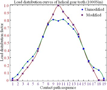
The clockwise diagonal method is proposed to optimize teeth profile modification. The helical gear parameters and material parameters used in the present paper are listed in Table 3. The no-load teeth surface imprinting and geometric transmission errors are shown in Fig. 20; the bar diagram of the mesh-in impact load of the helical gear is shown in Fig. 21; the load distribution curve of the helical gear is shown in Fig. 22; and the optimized clockwise diagonal modification curve and surface is shown in Fig. 23.
The following contributions can be obtained based on Figs. 20-23 and Table 3.
Table 3Parameters of helical gear pairs
Gear geometric parameter | Pinion gear | Large gear |
Normal modulus (mm) | 8 | 8 |
Tooth number | 19 | 47 |
Tooth width (mm) | 75 | 75 |
Shaft length (mm) | 200 | 200 |
Shaft radius (mm) | 45 | 55 |
Pressure angle (°) | 20 | 20 |
Helix angle (°) | 9.92 | 9.92 |
Weight (kg) | 7.8 | 40.2 |
Moment of inertia (kg⋅m2) | 0.018 | 0.387 |
Density (kg/m3) | 7850 | |
Damping ratio coefficient | 0.10 | |
Fig. 20No-load teeth surface imprinting and geometric transmission errors
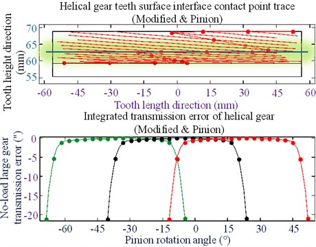
Fig. 21Bar diagram of meshing-in impact load of helical gear
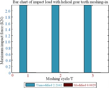
Fig. 22Load distribution curves of helical gear teeth (1000 Nm)
(1) For minimizing the mesh-in impact and improving working efficiency, all modifications are placed in the meshing gear pair. The large gear pinion errors occurs when no-load is detected by changing the minimum value of the mesh-in impact; then, the contact points trace of the tooth surface of the helical gear small wheel is obtained with the optimized modification.
(2) The tooth clockwise diagonal modification has an important influence on tooth surface load distribution, which can improve the offset load caused by the installation error and increase the bearing load capability of the tooth.
(3) The modified parameters can be obtained by applying the clockwise diagonal modification method.
(4) After optimizing the modification, a single tooth meshing area is generated on the tooth surface, and the meshing gear pair longer bears the load when meshing in and out; the minimum value of mesh-in impact is reduced by 93 %.
Fig. 23Optimized clockwise diagonal modification curve and surface
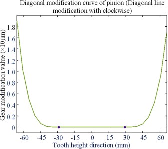
a) Modification curve
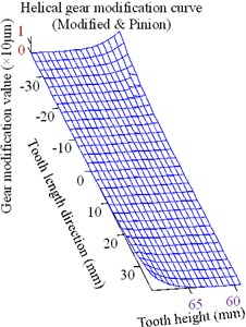
b) Modification surface
3.3. Optimization analysis for spur gear
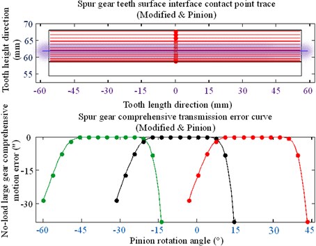
No-load teeth surface imprinting and geometric transmission errors are shown in Fig. 24; the bar graph of the mesh-in impact load of the spur gear is shown in Fig. 25; the load distribution curve of the spur gear is shown in Fig. 26; and the optimized clockwise diagonal modification curve and surface is shown in Fig. 27. The spur gear parameters and material parameters used in this study are listed in Table 4.
Fig. 24No-load teeth surface imprinting and geometric transmission errors
Based on the results shown in Figs. 24-27 and Table 4, the following conclusions can be drawn.
(1) Mesh-in impact load after modification is obviously reduced compared with the previous modification.
(2) The results show that the minimum value of mesh-in impact after modification decreased by 10 %, i.e., the minimum value of mesh-in impact reduced by 90 %;
(3) After optimizing the modification, a single tooth meshing area is generated on the tooth surface; this area is expanded further than that using the no modifications.
Fig. 25Bar graph of meshing-in impact load of spur gear
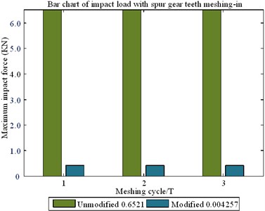
Fig. 26Load distribution curves of spur gear teeth (1000 Nm)
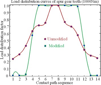
Fig. 27Optimized tooth profile modification curve and surface
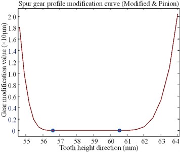
a) Profile modification curve
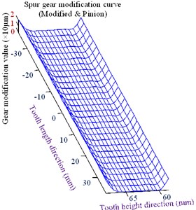
b) Profile Modification surface
Table 4Parameters of spur gear pairs
Gear geometric parameter | Pinion gear | Large gear |
Modulus (mm) | 6 | 6 |
Tooth number | 19 | 48 |
Tooth width (mm) | 75 | 75 |
Shaft length (mm) | 200 | 200 |
Shaft radius (mm) | 45 | 55 |
Pressure angle (°) | 20 | 20 |
Helix angle (°) | 7.5 | 38.6 |
Weight (kg) | 0.016 | 0.35 |
Moment of inertia (kg⋅m2) | 7850 | |
Density (kg/m3) | 0.10 | |
Damping ratio coefficient | 6 | |
4. Conclusions
In this study, the gear meshing impact combined with the mesh-in impact velocity model was proposed to analyze the teeth surface optimized modification. The gear meshing impact was synthesized using no-load motion error, load distribution coefficient, and maximum impact force in the actual meshing point along the teeth profile normal line of action. The engagement gear pairs with the mesh-in impact load lead to modifications of contact path and transmission errors, which affects the marine ship power rear drive gears under load. The following conclusions are obtained:
1) Uniform gear contact surface pressure suppresses the TED of tooth profile, reduces vibration and noise, and weakens initial mesh-in impact.
2) Optimal tooth surface modification can improve the effect of thermal elastic deformation of tooth surface on gear transmission performance, and improve tooth surface scratch resistance load capacity. Real-time lubrication conditions cannot be ignored when analyzing gear vibration and noise and describing instantaneous impact of mesh tooth surfaces.
3) Gear tooth thermal elastic deformation in initial meshing is the largest and instantaneous impact velocity reaches the peak value, and then impact force of mesh-in is the maximum.
After optimizing the modification, the mesh-in impact load after modification was reduced compared with that before modification. Further, a single tooth meshing area was generated on the tooth surface, and the area was expanded to more than that of the nonmodified spur gear. The results show that the minimum values of the meshing-in impact after the modification are reduced considerably.
References
-
J. Bruyère, X. Gu, and P. Velex, “On the analytical definition of profile modifications minimising transmission error variations in narrow-faced spur helical gears,” Mechanism and Machine Theory, Vol. 92, pp. 257–272, Oct. 2015, https://doi.org/10.1016/j.mechmachtheory.2015.06.001
-
C. Xie, L. Hua, J. Lan, X. Han, X. Wan, and X. Xiong, “Improved analytical models for mesh stiffness and load sharing ratio of spur gears considering structure coupling effect,” Mechanical Systems and Signal Processing, Vol. 111, pp. 331–347, Oct. 2018, https://doi.org/10.1016/j.ymssp.2018.03.037
-
D. Miler, A. Lončar, D. Žeželj, and Z. Domitran, “Influence of profile shift on the spur gear pair optimization,” Mechanism and Machine Theory, Vol. 117, pp. 189–197, Nov. 2017, https://doi.org/10.1016/j.mechmachtheory.2017.07.001
-
H. Abderazek, D. Ferhat, and A. Ivana, “Adaptive mixed differential evolution algorithm for bi-objective tooth profile spur gear optimization,” The International Journal of Advanced Manufacturing Technology, Vol. 90, No. 5–8, pp. 2063–2073, Oct. 2016, https://doi.org/10.1007/s00170-016-9523-2
-
Z. Chen, W. Zhai, Y. Shao, and K. Wang, “Mesh stiffness evaluation of an internal spur gear pair with tooth profile shift,” Science China Technological Sciences, Vol. 59, No. 9, pp. 1328–1339, Apr. 2016, https://doi.org/10.1007/s11431-016-6090-6
-
H. Ma, X. Pang, R. Feng, and B. Wen, “Evaluation of optimum profile modification curves of profile shifted spur gears based on vibration responses,” Mechanical Systems and Signal Processing, Vol. 70–71, pp. 1131–1149, Mar. 2016, https://doi.org/10.1016/j.ymssp.2015.09.019
-
X. Liang, H. Zhang, M. J. Zuo, and Y. Qin, “Three new models for evaluation of standard involute spur gear mesh stiffness,” Mechanical Systems and Signal Processing, Vol. 101, pp. 424–434, Feb. 2018, https://doi.org/10.1016/j.ymssp.2017.09.005
-
H. Ma, J. Zeng, R. Feng, X. Pang, and B. Wen, “An improved analytical method for mesh stiffness calculation of spur gears with tip relief,” Mechanism and Machine Theory, Vol. 98, pp. 64–80, Apr. 2016, https://doi.org/10.1016/j.mechmachtheory.2015.11.017
-
M. Zajíček and J. Dupal, “Analytical solution of spur gear mesh using linear model,” Mechanism and Machine Theory, Vol. 118, pp. 154–167, Dec. 2017, https://doi.org/10.1016/j.mechmachtheory.2017.08.008
-
M. Franulovic, K. Markovic, Z. Vrcan, and M. Soban, “Experimental and analytical investigation of the influence of pitch deviations on the loading capacity of HCR spur gears,” Mechanism and Machine Theory, Vol. 117, pp. 96–113, Nov. 2017, https://doi.org/10.1016/j.mechmachtheory.2017.07.006
-
Y. Luo, N. Baddour, and M. Liang, “A shape-independent approach to modelling gear tooth spalls for time varying mesh stiffness evaluation of a spur gear pair,” Mechanical Systems and Signal Processing, Vol. 120, pp. 836–852, Apr. 2019, https://doi.org/10.1016/j.ymssp.2018.11.008
-
X. Liang, M. J. Zuo, and Z. Feng, “Dynamic modeling of gearbox faults: A review,” Mechanical Systems and Signal Processing, Vol. 98, pp. 852–876, Jan. 2018, https://doi.org/10.1016/j.ymssp.2017.05.024
-
Saxena A., Parey A., Chouksey M. “Time varying mesh stiffness calculation of spur gear pair considering sliding friction and spalling defects”, Engineering Failure Analysis, Vol. 70, pp. 200–211, 2016, https://doi.org/10.1016/j.engfailanal.2016.09.003
-
Y. Lei, Z. Liu, D. Wang, X. Yang, H. Liu, and J. Lin, “A probability distribution model of tooth pits for evaluating time-varying mesh stiffness of pitting gears,” Mechanical Systems and Signal Processing, Vol. 106, pp. 355–366, Jun. 2018, https://doi.org/10.1016/j.ymssp.2018.01.005
-
Y. Luo, N. Baddour, and M. Liang, “Effects of gear center distance variation on time varying mesh stiffness of a spur gear pair,” Engineering Failure Analysis, Vol. 75, pp. 37–53, May 2017, https://doi.org/10.1016/j.engfailanal.2017.01.015
-
M. Ankouni, A. Lubrecht, and P. Velex, “Modelling of damping in lubricated line contacts – Applications to spur gear dynamic simulations,” Proceedings of the Institution of Mechanical Engineers, Part C: Journal of Mechanical Engineering Science, Vol. 230, No. 7–8, pp. 1222–1232, Jan. 2016, https://doi.org/10.1177/0954406216628898
-
J. Liu, Z. Shi, and Y. Shao, “An analytical model to predict vibrations of a cylindrical roller bearing with a localized surface defect,” Nonlinear Dynamics, Vol. 89, No. 3, pp. 2085–2102, May 2017, https://doi.org/10.1007/s11071-017-3571-5
-
W. Yu and C. K. Mechefske, “Analytical modeling of spur gear corner contact effects,” Mechanism and Machine Theory, Vol. 96, pp. 146–164, Feb. 2016, https://doi.org/10.1016/j.mechmachtheory.2015.10.001
-
G. E. Morales-Espejel, P. Rycerz, and A. Kadiric, “Prediction of micropitting damage in gear teeth contacts considering the concurrent effects of surface fatigue and mild wear,” Wear, Vol. 398–399, pp. 99–115, Mar. 2018, https://doi.org/10.1016/j.wear.2017.11.016
-
W. Yu, C. K. Mechefske, and M. Timusk, “The dynamic coupling behaviour of a cylindrical geared rotor system subjected to gear eccentricities,” Mechanism and Machine Theory, Vol. 107, pp. 105–122, Jan. 2017, https://doi.org/10.1016/j.mechmachtheory.2016.09.017
-
C. Hu, W. A. Smith, R. B. Randall, and Z. Peng, “Development of a gear vibration indicator and its application in gear wear monitoring,” Mechanical Systems and Signal Processing, Vol. 76–77, pp. 319–336, Aug. 2016, https://doi.org/10.1016/j.ymssp.2016.01.018
-
H. Jiang and F. Liu, “Dynamic features of three-dimensional helical gears under sliding friction with tooth breakage,” Engineering Failure Analysis, Vol. 70, pp. 305–322, Dec. 2016, https://doi.org/10.1016/j.engfailanal.2016.09.006
-
Weis P., Kučera Ľ., Pecháč P., Močilan M. “Modal analysis of gearbox housing with applied load,” Procedia Engineering, Vol. 192, p. 953-958, 2017, https://doi.org/10.1016/j.proeng.2017.06.164
-
D. Miler, M. Hoić, S. Škec, and D. Žeželj, “Optimisation of polymer spur gear pairs with experimental validation,” Structural and Multidisciplinary Optimization, Vol. 62, No. 6, pp. 3271–3285, Jul. 2020, https://doi.org/10.1007/s00158-020-02686-1
-
F. Zheng, M. Zhang, W. Zhang, and X. Guo, “Research on the tooth modification in gear skiving,” Journal of Mechanical Design, Vol. 140, No. 8, Jun. 2018, https://doi.org/10.1115/1.4040268
-
B. Yu and K. Ting, “Compensated conjugation and gear tooth modification design,” Journal of Mechanical Design, Vol. 138, No. 7, May 2016, https://doi.org/10.1115/1.4032264
-
J. Chang and I. Chang, “Design of high ratio gear reducer using vernier differential theory,” Journal of Mechanical Design, Vol. 143, No. 2, Aug. 2020, https://doi.org/10.1115/1.4047347
-
Y. Hu, D. Talbot, and A. Kahraman, “A gear load distribution model for a planetary gear set with a flexible ring gear having external splines,” Journal of Mechanical Design, Vol. 141, No. 5, Jan. 2019, https://doi.org/10.1115/1.4041583
-
P. Rai and A. G. Barman, “An approach for design optimization of helical gear pair with balanced specific sliding and modified tooth profile,” Structural and Multidisciplinary Optimization, Vol. 60, No. 1, pp. 331–341, Jan. 2019, https://doi.org/10.1007/s00158-019-02198-7
-
U. Weinberger, M. K. Otto, and K. Stahl, “Closed-form calculation of lead flank modification proposal for spur and helical gear stages,” Journal of Mechanical Design, Vol. 142, No. 3, Dec. 2019, https://doi.org/10.1115/1.4045396
-
C. Yang, Q. Li, and Q. Chen, “Decoupled elastostatic stiffness modeling of parallel manipulators based on the rigidity principle,” Mechanism and Machine Theory, Vol. 145, p. 103718, Mar. 2020, https://doi.org/10.1016/j.mechmachtheory.2019.103718
-
Z. Xiao, C. Zhou, S. Chen, and Z. Li, “Effects of oil film stiffness and damping on spur gear dynamics,” Nonlinear Dynamics, Vol. 96, No. 1, pp. 145–159, Jan. 2019, https://doi.org/10.1007/s11071-019-04780-6
-
C. J. Zhou, L. J. Pan, J. Xu, X. Han, “Non-Newtonian thermal elastohydrodynamic lubrication in point contact for a crowned herringbone gear drive,” Tribology International, Vol. 116, pp. 470–481, 2018, https://doi.org/10.1016/j.triboint.2017.08.007
-
H. Liu, H. Liu, C. Zhu, and R. G. Parker, “Effects of lubrication on gear performance: A review,” Mechanism and Machine Theory, Vol. 145, p. 103701, Mar. 2020, https://doi.org/10.1016/j.mechmachtheory.2019.103701
Cited by
About this article

The authors would like to thank the Northeast Forestry University (NEFU), Heilongjiang Institute of Technology (HLJIT), and the Harbin Institute of Technology (HIT) for their support.
The research topic was supported by the Doctoral Research Startup Foundation Project of Heilongjiang Institute of Technology (Grant No. 2020BJ06, Yongmei Wang, HLJIT), the Natural Science Foundation Project of Heilongjiang Province (Grant No. LH2019E114, Baixue Fu, HLJIT), the Basic Scientific Research Business Expenses (Innovation Team Category) Project of Heilongjiang Institute of Engineering (Grant No. 2020CX02, Baixue Fu, HLJIT), and the Special Project for Double First-Class-Cultivation of Innovative Talents (Grant No. 000/41113102, Jiafu Ruan, NEFU).
