Abstract
The tooth contact analysis model is introduced for cylindrical gear with high-order topological modification and misalignment. According to the generation principle of gear, the tooth surface equation of double-crowned gear by using worm grinding wheel is derived. Based on the gear meshing theory, a tooth contact model of cylindrical gear considering errors and high-order topological modification is established. Taking helical gears as an example, the effects of errors and four different combinations of modification curves on the contact marks and transmission errors of tooth surface were analyzed. Results show that the paths of contact change dramatically with different combinations of modification curves. With the increasing of the order of modification curve, the contact path transitions smoothly in the middle of the tooth width, while the total length of the major axis of the contact ellipses increase significantly compared with taking the quadratic parabola modification. With proper parameters of the modification, the apex of transmission error function is flatter and its amplitude decreases which further reduces the vibration of gear transmission to installation error. The finite element method is applied to validate the proposed analysis model. The results are basically consistent and the maximum error is within 3.5 %.
1. Introduction
Cylindrical gears have been widely applied in the main reducer of helicopters to realize split-torque transmission because of their easy fabrication and installation.
Due to the manufacturing and installation errors, the actual contact point of gears deviates from the theoretical one, resulting in contact deflection and stress concentration, which reduces the life of gears. In addition, the gear base pitch changes due to the elastic deformation of the gear under load, resulting in meshing impact and vibration. Tooth surface modifications have become an important phase of gear design that can remarkably enhance gear performance and reduce the vibration and noise. The tooth contact analysis of cylindrical gear can simulate the gear contact with high-order topological modification and misalignment under light load. The meshing impressions and transmission errors obtained by the analysis are important indexes to measure the transmission performance of gears. It is widely believed that there is strong correlation between the above two indexes and mechanical properties, friction properties, the dynamic performance of gears, the correlation of them has been clarified and described by many authors [1-14]. The research of the influence of modification on the gear meshing is also the basis for the modification and optimization design of the gears [15-24].
Many studies have focused on the analysis of gear contact path and transmission error. Litvin et al. [25] proposed the tooth contact analysis (TCA), and stress analysis model for a new type of Novikov-Wildhaber helical gear drive with double-crowned surface, the results show that taking the parabolic modification of the tooth surface can obtain continuous transmission error, reduce the sensitivity of the meshing performance to the installation error, as well as the contact and bending stress. I. G.-Perez and Litvin et al. [26] investigated the path of contact and transmission errors of modified helical gears with three types of topology. Tsay et al. [27] studied the contact characteristics of moulded face-gear drives with novel profile modification methodology. Peng Y. et al. [28] proposed a model of contact for helical gears with modification and misalignment, the influences of errors and modification on tooth surface contact are studied. Simon [29] studied the influence of tooth modifications on tooth contact in face-hobbed spiral bevel gears. Velex et al. [30] proposed an analytical method to approximately calculate the quasi-static transmission error of cylindrical gears, the results were in good agreement with the numerical calculation results, pointing out that there is a certain law between tooth profile modification and transmission error fluctuation. Ni [31] studied the influence of modification on the contact and transmission error of the crossed beveloid gear. Lin et al. [32] calculated the static and dynamic transmission errors of helical gear pairs by using finite element method, comprehensively considering the manufacturing error, installation error and modification.
Many research have focused on the influence of modification on tooth surface contact, most of them considered simple modification methods and modification curves, only a few studied the influence of high order modification curves on tooth surface contact, as well as the comparison of the order of modified curve on gear transmission. So this paper presents a tooth contact analysis model to determine the contact marks and transmission errors of helical gears with high-order topological modification and misalignments. The influence of errors and different combinations of modification curves on the gear contact were analyzed. A finite element method is utilized to validate the proposed analysis model.
2. Modeling
2.1. Gear modified
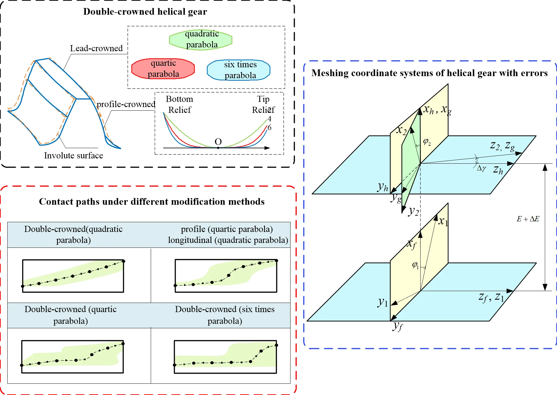
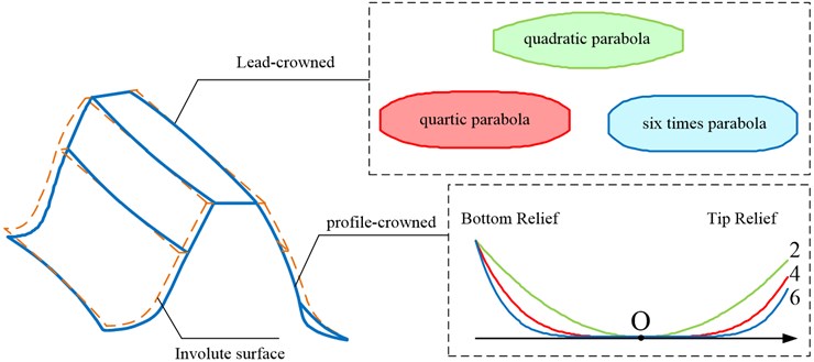
Fig. 1 shows the double-crowned helical gear which includes profile crowning and longitudinal modification with high- order modification curve. Studies have shown that double-crowned enables to provide a parabolic function of transmission errors and reduce the noise and vibration of gear drive [32]. This paper proposes higher order double-crowned gear model, the modification curve includes quadratic parabola (2), quartic parabola (4) and six times parabola (6).
Fig. 1Double-crowned helical gear
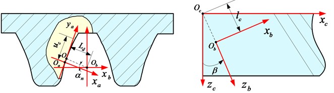
The profile-crowned tooth surface of a helical gear is generated by a rack cutter which has a parabolic profile on the normal section, as shown in Fig. 2. The profile of the rack cutter in coordinate system can be represented as:
where , is the parabola coefficient. is the matrix of coordinate transformation from to .
If the tooth profile modification curve of the rack cutter is a quadratic parabola or a higher-order quartic parabola, the left side tooth surface equation of the rack cutter in system can be expressed as:
Fig. 2Coordinate systems of helical rack cutter
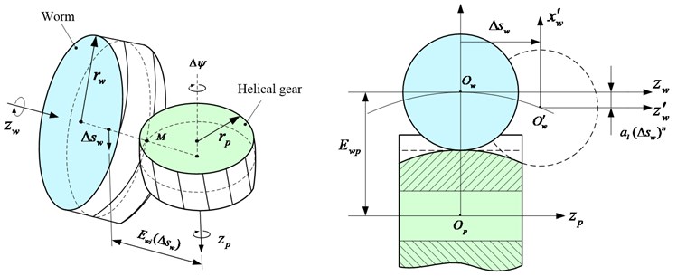
In this paper, the CNC worm wheel gear grinding machine is used to modify the tooth surface of helical gear to get the high-order parabolic modification. Assuming that the tooth surface of the worm grinding wheel is internal meshing with the tooth surface of the rack cutter, the tooth surface of the worm grinding wheel is generated by the modified rack cutter. The profile of worm grinding wheel can be expressed as:
The motion relation of helical gear and worm grinding wheel is shown in Fig. 3, and are the axes of helical gear and worm grinding wheel, when feeds axially along the helical gear, the worm grinding wheel is controlled to feed radially and the instantaneous shortest center distance between the worm grinding wheel and the helical gear satisfies the equation Eq. (6):
When 2, the worm grinding wheel moves in a quadratic parabola along the axis of the helical gear, and when 4 or 6, a high-order parabolic longitudinal modification can be obtained. The double-crowned tooth surface is determined as:
Fig. 3Generation of modified helical gear by worm
2.2. Point contact model of gears
The gear tooth surfaces are in point contact due to the installation error and manufacturing error. Fig. 4 is the meshing coordinate systems of helical gear considering center distance error and axis angle error.
Fig. 4Meshing coordinate systems of helical gear with errors
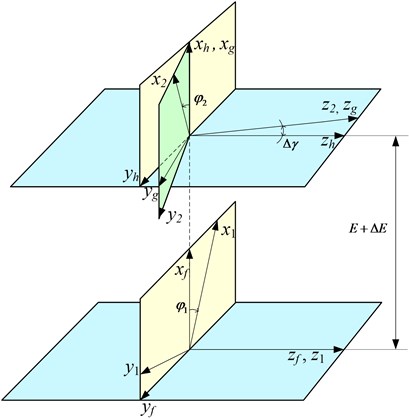
Coordinate systems is fixed to the gearbox housing, and are rigidly connected to the pinion and the gear respectively. and are the auxiliary transformation coordinate systems. is rotation angle of the pinion. , are the center distance error and the shaft angle error of gears. The meshing equation of tooth surface in can be expressed as:
where , represent the tooth surface equation of gears in and , , are the tooth profile parameters of the cutter. Through the above analysis, the corresponding principal curvature and principal direction of each instantaneous contact point can be determined respectively, so as to obtain the meshing impressions in tooth surface.
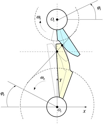
Fig. 5 is the schematic diagram of gear meshing rotation. Due to the influence of manufacturing and assembly error, tooth surface modification and elastic deformation of loaded teeth, the driving gear rotates evenly, while the driven gear fails to rotate evenly.
Fig. 5Rotation of gears
The difference between the actual position and the ideal position of the gear is defined as the transmission error (TE). It can be represented as:
where and represent initial engagement angle of pinion and gear, and represent the actual engagement angle of pinion and gear.
2.3. Tooth contact ellipse
The instantaneous contact area of the tooth surface expands into an elliptical area under the load. represents the tooth surface equation, the normal curvature of point on the surface can be represented as:
where , , are the first fundamental quantity of the surface, , , are the second fundamental quantity of the surface. , , , , , , is the unit normal vector of the surface.
Considering , then:
Eliminate , then:
The principal curvature and principal direction of the surface can be obtained by solving Eqs. (11) and Eq. (12) respectively.
Fig. 6Common section projection of contact ellipse
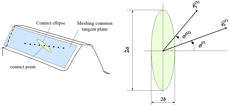
Fig. 6 shows the projection of the contact ellipse on the common tangent plane of the meshing tooth surface.
The directed angle from the first principal direction on the pinion tooth surface to the first principal direction on the gear tooth surface is defined as . Given the principal curvature and direction of two contact tooth surfaces, the normal curvature in any direction can be expressed according to the Euler formula of normal curvature:
where , , . is the angle between the main direction and the minor axis of the instantaneous contact ellipse of point on :
Then the length of the major and minor semi-axes of the contact ellipse ( and ) can be represented as:
3. Results and discussion
The effects of profile crowning, lead modification and misalignment on tooth surface contact and transmission error of helical gears are investigated based on the proposed model. The parameters of the helical gear pair are shown in Table 1. Considering the design efficiency, only the pinion tooth surface modification is considered in this work.
Table 1Parameters of helical gears
Parameters | value |
Tooth number of pinion | 23 |
Tooth number of gear | 91 |
Normal module (mm) | 5 |
Tooth width (mm) | 50 |
Pressure angle ( °) | 20 |
Helix angle ( °) | 25 |
Addendum height coefficient | 1 |
Clearance coefficient | 0.25 |
Elastic Modulus (GPa) | 210 |
Input torque (N∙m) | 300 |
3.1. Meshing simulation of helical gears
3.1.1. Effect of installation error
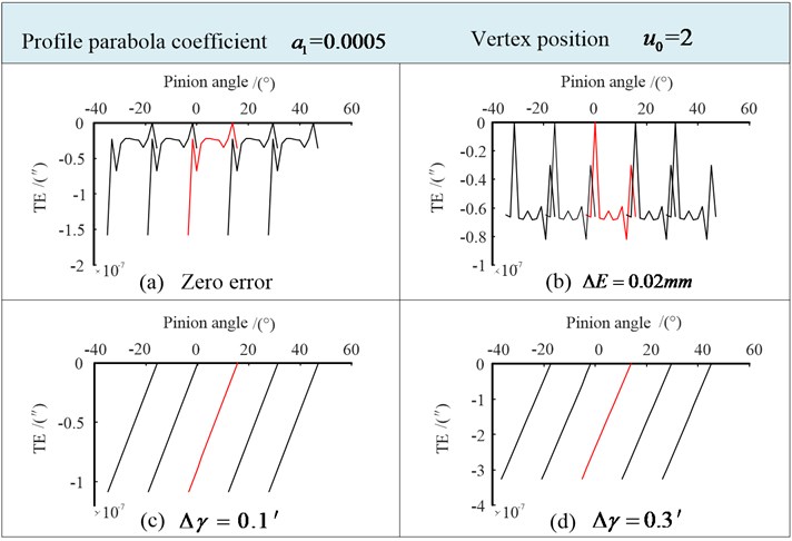
The profile parabola coefficient 0.0005, Vertex position 2. The effect of installation error on tooth contact mark (contact line and contact path) are shown in Fig. 7. When there is no installation error, the tooth contact mark is shown in Fig. 7(a). The tooth contact mark caused by 0.02 mm is shown in Fig. 7(b). Figs. 7(c) and 7(d) show the mark caused by 0.1' and 0.3'.
Fig. 7Tooth contact mark
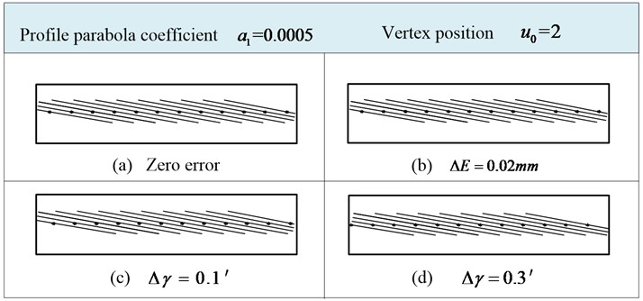
The contact lines of the helical gear are almost unchanged when there is a large center distance error, and the path of contact does not deviate along the tooth width direction, which is consistent with the characteristic that the cylindrical gear is insensitive to the center distance error. When there is a small shaft angle error , the contact path moves along the direction of the tooth width, but no obvious change is found in the length and direction of the long axis of the contact ellipse.
The transmission errors in the above four states are shown in Fig. 8. The amplitude of transmission error is less than 4×10⁻⁷″ when there is center distance error.
The transmission error is turn into a discontinuous straight line due to the existence of shaft angle error, which will cause the discontinuity of transmission motion between adjacent teeth and resulting in the meshing impact and vibration. It further indicates that gear tooth meshing is sensitive to the shaft angle error. The amplitude of the transmission error increases with the increase of the shaft angle error.
Fig. 8Transmission errors
3.1.2. Double-crowned (quadratic parabola)
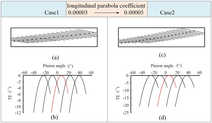
Four cases in Table 2 are analyzed to study the influence of the double-crowned on gear tooth meshing state which is generated by worm considering the quadratic parabola.
Using the parameters of Case 1 and Case 2, we obtain the tooth contact marks. As shown in Fig. 9(a) and (c), the path of contact was significantly deflected along the tooth surface due to the longitudinal modification compared with Fig. 7(d), and the larger the parabola coefficient, the more obvious the deflection.
Table 2Double-crowned (quadratic parabola)
Modification parameters | Double-crowned (2) | |||
Case 1 | Case 2 | Case 3 | Case 4 | |
Parabola coefficient | 0.0005 | 0.0005 | 0.0005 | 0.0008 |
Vertex position (mm) | 2.0 | 2.0 | 2.5 | 2.5 |
Parabola coefficient | 0.00003 | 0.00005 | 0.00005 | 0.00005 |
Shaft angle error (') | 0.3 | 0.3 | 0.3 | 0.3 |
It can be observed in Fig. 9(b), (d), the transmission error curve presents a continuous parabolic shape due to the parabola longitudinal modification. Compared with the discontinuous linear function of transmission error, the angular velocity runout at the cycle connection point of gear tooth engagement will be reduced. This shows that the quadratic parabola longitudinal modification of tooth can compensate the influence of the shaft angle error on meshing. With the increase of , the value of transmission error also increases for case 2.
Fig. 9Tooth contact mark and transmission errors (Case 1, Case 2)
With the increase of the vertex position in case 3, the contact points in Fig. 10(a) are shifted downward and deviated along the tooth width direction compared with the contact path in Fig. 9(c), but the length and direction of the long axis of the contact ellipse do not change significantly. With the increase of , the contact points of case 4 move to close to the pitch circle, while the long axis of the contact ellipse is obviously shorter, it is not conducive to the bearing capability of the tooth.
Fig. 10Tooth contact mark and transmission errors (Case 3, Case 4)
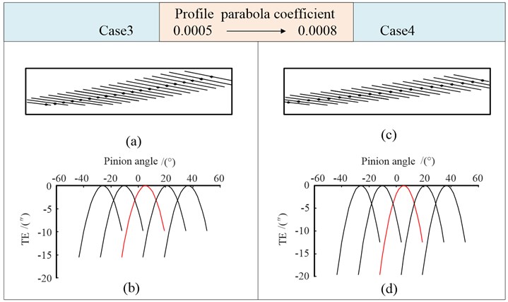
The transmission error of case 3 is smaller than case 2. With the increase of in case 4, the value of the transmission error increases. Therefore, we should reasonably design the parameters of modification.
3.1.3. Profile-crowned (quartic parabola) + lead-crowned (quadratic parabola)
Cases 5-8 in Table 3 are analyzed to study the influence of quartic parabola profile modification on the meshing state. In Table 3, is the quartic parabola coefficient. is the quadratic parabola coefficient.
Table 3Profile-crowned (quartic parabola) + lead-crowned (quadratic parabola)
Modification parameters | Profile-crowned (4) + lead-crowned (2) | |||
Case 5 | Case 6 | Case 7 | Case 8 | |
Parabola coefficient | 0.00001 | 0.00001 | 0.00001 | 0.00002 |
Vertex position (mm) | 2.0 | 2.0 | 2.5 | 2.5 |
Parabola coefficient | 0.00003 | 0.00005 | 0.00005 | 0.00005 |
Shaft angle error | 0.3 | 0.3 | 0.3 | 0.3 |
In Fig. 11, the path of contact changes into an S-shaped when taking a quartic parabola profile modification. Compared with Fig. 10, the instantaneous contact points move down at the entry end, and move up at the exit end. The long axis of the contact ellipse becomes significantly longer at the middle of the tooth width. In case 6, with the increase of the longitudinal modification coefficient, the contact points move further down at the entry end and move up at the exit end, while they remain basically unchanged at the middle of the tooth width.
Fig. 11Tooth contact mark and transmission errors (Case 5, Case 6)
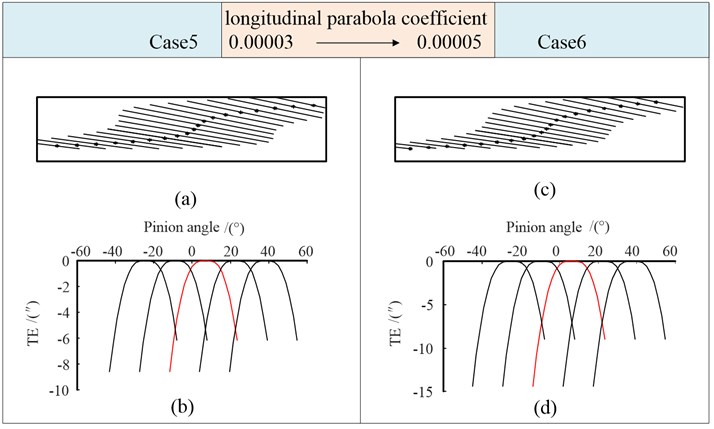
The apex of the parabolic transmission error in Fig. 11 is almost “flattened”, which is slightly smaller than the transmission error value in Fig. 10. The amplitude of it at the transition point decreases, and the angle between the two tangents at the transition point increases. The curve is smooth, which not only reduces the sensitivity of the gear transmission to installation errors, but also reduces the vibration and impact of gears under light load. With the increase of the longitudinal modification coefficient, the value of transmission error increases.
Compared with case 6, is changed in case 7, is increased in case 8. The analysis results are shown in Fig. 12.
Compared with Fig. 11(c), the path of contact in Fig. 12(a) shifted downward and deviated along the tooth width direction. The length and direction of the long axis of the contact ellipse do not change significantly.
In Fig. 12(c), the long axis of the contact ellipse becomes shorter because of the increase in the crowning of the tooth profile. The contact points move up at the entry end, and move down at the exit end. The contact points near the middle of the tooth width are basically unchanged. We can see that the path of contact transitions smoothly across the entire tooth width.
As shown in Fig. 12(b), the transmission error of case 7 is smaller than case 6. The increase in the crowning of the tooth profile leads to an increase in transmission error.
Fig. 12Tooth contact mark and transmission errors (Case 7, Case 8)
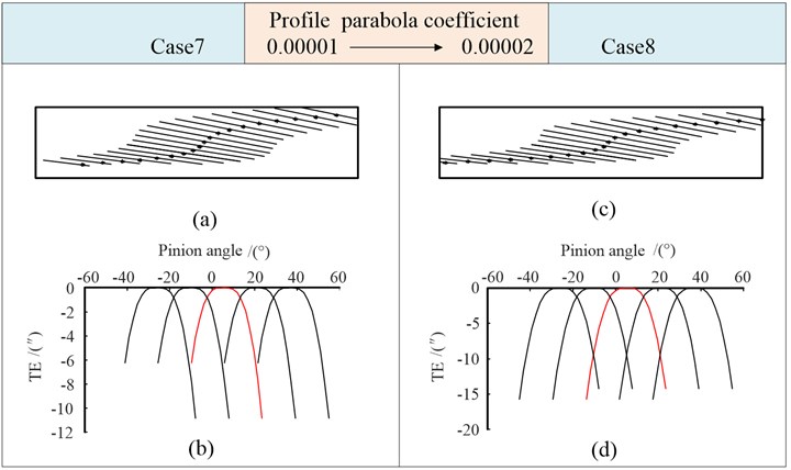
The above results show that generate the profile by a higher-order quartic parabola does not change the basic properties of the transmission error compared with Figs. 9-10. While the tip of the transmission error curve is “flattened”. A better contact path than Figs. 9-10 can be achieved by taking a proper quartic parabola profile modification.
3.1.4. Double-crowned (quartic parabola)
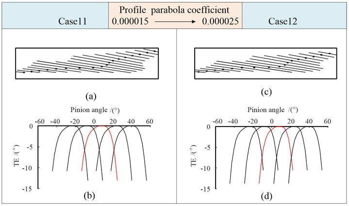
In order to further analyze the influence of the high-order longitudinal modification on the contact state of the gear, case 9-12 are analyzed. Both and are the quartic parabola coefficient in Table 4.
Table 4Double-crowned (quartic parabola)
Modification parameters | Double-crowned (4) | |||
Case 9 | Case 10 | Case 11 | Case 12 | |
Parabola coefficient | 0.000015 | 0.000015 | 0.000015 | 0.000025 |
Vertex position (mm) | 2.0 | 2.0 | 2.5 | 2.5 |
Parabola coefficient | 5×10⁻⁸ | 8×10⁻⁸ | 8×10⁻⁸ | 8×10⁻⁸ |
Shaft angle error (') | 0.3 | 0.3 | 0.3 | 0.3 |
Compared with Fig. 12, taking the quartic parabola longitudinal modification, the contact points at the entry and exit ends do not change significantly. The contact point transitions smoothly and in a straight line in the middle of the tooth width. While the length of the major axis of the contact ellipses near the middle of the tooth width increase. In Case 10, With the increase of , the contact points at the entry and exit ends deviate along the tooth width direction, and the contact path in the middle of the tooth width is basically unchanged.
The function of transmission error in Fig. 13(b) is flatter than it in Figs. 11-12. This shows that the quadric parabolic longitudinal modification further reduces the sensitivity of gear transmission to installation error. It is very beneficial to reduce the vibration and impact of gear transmission under light load. In Fig. 13(d), With the increase of , the value of transmission error increases.
The vertex parameters is changed from 2.0 to 2.5 in case 11, is increased in case 12. The simulation results are shown in Fig. 14. It can be seen that the change of affects the position of the contact point, and the increase of makes the long axis of the contact ellipse shorter. When the double-crowned is generated considering the quadric parabola, the function of transmission error under the given cases has a slight change in shape, but a small difference in numerical value.
Fig. 13Tooth contact mark and transmission errors (Case 9, Case 10)
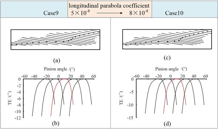
Fig. 14Tooth contact mark and transmission errors (Case 11, Case 12)
3.1.5. Double-crowned (six times parabola)
Cases 13-16 in Table 5 are analyzed to study the influence of the six times parabolic modification of tooth surface on gear meshing.
Table 5Double-crowned (six times parabola)
Modification parameters | Double-crowned (6) | |||
Case 13 | Case 14 | Case 15 | Case 16 | |
Parabola coefficient | 0.00000035 | 0.00000035 | 0.00000035 | 0.0000006 |
Vertex position (mm) | 2.0 | 2.0 | 2.5 | 2.5 |
Parabola coefficient | 3×10-11 | 1×10⁻¹⁰ | 1×10⁻¹⁰ | 1×10⁻¹⁰ |
Shaft angle error (') | 0.3 | 0.3 | 0.3 | 0.3 |
Fig. 15Tooth contact mark and transmission errors (Case 13, Case 14)
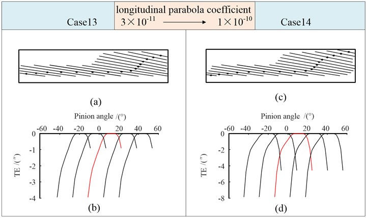
The contact points in Fig. 15(a) transitions smoothly in the tooth root and the middle area of the tooth width, and the contact path is flat and almost straight compared with its in Fig. 13 and Fig. 14. When the amount of modification for quartic parabola and six times parabola is roughly the same, the long axis of the instantaneous contact ellipse becomes significantly longer at the entry and exit ends, and the total length of the long axis of each instantaneous contact ellipse is longer than that of the quartic parabola modification, and the meshing is smoother.
The functions of transmission error in Fig. 15 are high-order curves, which are conducive to reducing vibration and impact of gears under light load. The value is smaller when the six times parabolic modification is adopted. With the increase of , the value of transmission error in Fig. 15(d) increases.
The vertex parameters is changed from 2.0 to 2.5 in case 15, is increased to 0.0000006 in case 16. The simulation results are shown in Fig. 16. It can be seen that the influence characteristic of the parameters on the results is the same as that of quartic parabola modification.
3.2. Summary of contact
From the above analysis of case 1 to case 16, it is obvious that the use of high-order parabolic modification can achieve better contact mark than quadratic parabolic modification. When a high-order modification curve is used, the path of contact changes obviously compared with taking quadratic parabolic modification, the path is generally flat, and tends to be straight in the middle of the tooth surface. The contact area is significantly increased, which further improves the bearing capacity and stability of the gear transmission. It is beneficial to reduce the vibration and noise of transmission. The summary of contact paths and area under different combinations of modification is shown in Fig. 17.
Fig. 16Tooth contact mark and transmission errors (Case 15, Case 16)
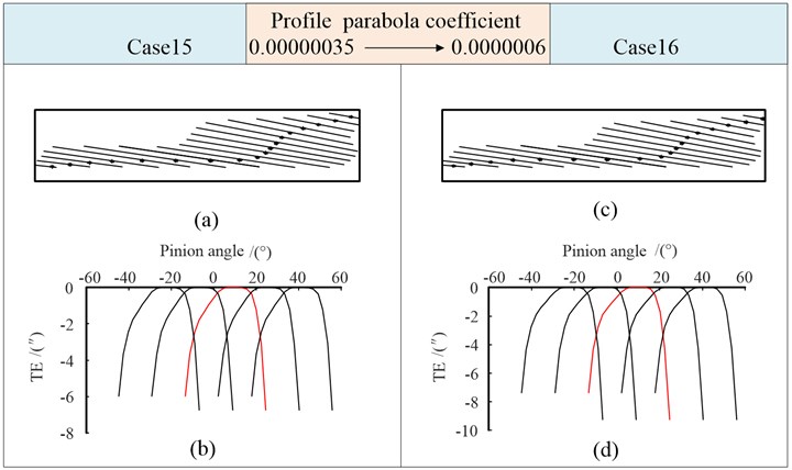
Fig. 17Contact paths under different modification methods

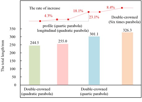
For case 2, case 6, case 10 and case 14, when the calculation step is unified, if there are 18 contact lines on the tooth surface, the total length of contact lines on the tooth surface with different modification combinations are shown in Fig. 18. It can be seen that the total length of contact lines increases with the continuous increase of modification curve order. Compared with the double-crowned (quadratic parabola) gears, the length of all contact lines increases to 255 mm when taking the profile (quartic parabola) and longitudinal (quadratic parabola), the rate of increase is 4.2 %. When taking the double-crowned (quartic parabola) modification, the length of all contact lines increases obviously to 301.1 mm, the rate of increase is 23.2 % compared with the double-crowned (quadratic parabola) gears. For the double-crowned (six times parabola) gears, it increases by 8.4 % compared with taking the quartic parabola modification, the rate of increase has dropped significantly.
Fig. 18The total length of contact lines on tooth surface
3.3. Model validation
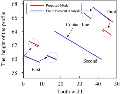
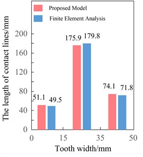
A finite element method is applied to validate the proposed model. The parameters of example are the same as case 2, case 10 and case 14 respectively. The entire tooth surface is divided into three sections along the tooth width direction: 0-15 mm, 15 mm-35 mm, 35 mm-50 mm, and the contact lines on the tooth surface are obtained by the finite element method and the proposed model respectively.
In the above three sections, for double-crowned (quadratic parabola) gears, the contact lines at the same meshing position are selected for comparison. The results are shown in Fig. 19(a). It can be seen that there are small differences for the directions of the first contact line and third one using the two methods. The direction of second one is virtually identical. And compared with the results of the proposed model, the length of contact line of the first and third ones by the finite element analysis are slightly shorter, but the second one is slightly longer.
Fig. 19Double-crowned (quadratic parabola)
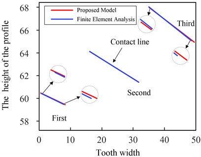
a) Contact lines on tooth surface
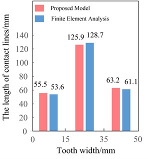
b) The length of contact lines
The contact lines on the tooth surface were added separately according to the three sections, the length of them are shown in Fig. 19(b). The sum of the length of contact lines is 55.5 mm, 125.9 mm and 63.2 mm in the three sections by the proposed model, and 53.6 mm, 128.7 mm, 61.1 mm respectively by the finite element analysis. The results obtained by the proposed model are basically consistent with its by finite element analysis, the maximum error is within 3.5 %. Compared with the results of the proposed model, the total length of contact lines of the first section (0-15 mm) and third ones (35 mm-50 mm) by the finite element analysis are slightly shorter, while in the second section (15 mm-35 mm) is slightly longer.
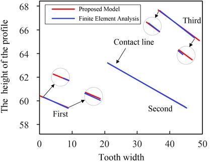
Fig. 20Double-crowned (quartic parabola)
a) Contact lines on tooth surface
b) The length of contact lines
Fig. 20(a) shows the contact lines by the finite element analysis and the proposed model of double-crowned (quartic parabola) gears. It can be observed that the comparative characteristics of the direction and length of the contact line at the same meshing position obtained by the two methods are consistent with those in Fig. 19(a). The sum of the length of contact lines in the three sections are shown in Fig. 20(b), the maximum errors of the results by the two methods are still within 3.5 %. Compared with the results of double-crowned (quadratic parabola) gears by the proposed model, in the 0-15 mm section, the sum of the length of contact line decreases by about 7.9 %, in the 15 mm-35 mm section, the value increases more obviously by about 39.7 %, and in the 35 mm-50 mm section, which increased by 17.2 %. It is obvious that the contact area in the middle of the tooth surface is enlarged, the transmission is more stable.
Fig. 21Double-crowned (six times parabola)
a) Contact lines on tooth surface
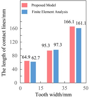
b) The length of contact lines
Fig. 21(a) show the results of double-crowned (six times parabola) gears by the two methods. The results obtained by the proposed model are still consistent with its by finite element analysis, the first contact line and third one obtained by the two methods have small differences in directions. The length of contact line of them by the finite element analysis are slightly shorter, while the second one is longer. In Fig. 21(b), compared with the results of double-crowned (quartic parabola) gears by the proposed model, the total length of contact line increases by about 27 % in the 0-15 mm section. While in the 15 mm-35 mm section, it decreases significantly by about 45.8 %. In the 35 mm-50 mm section, the total length of contact lines is 166.1 mm and 161.1 mm by the two methods with an obvious increase of about 124.2 %. Although the total length of contact lines on the tooth surface is increased compared with the double-crowned (quartic parabola) gears, but the sum of length of contact line in the middle section (15 mm-35 mm) of the tooth width decreased significantly, which is not good for the bearing capacity of gears.
4. Conclusions
This paper presents a tooth contact analysis model to study the tooth contact marks and transmission errors of gears, considering misalignments and different combinations of high-order topological modification. The tooth surface equation with double-crowned by using worm grinding wheel is derived using the generation principle of gear. Based on the gear meshing theory, the tooth contact model of cylindrical gear with errors and high-order topological modification is established. The effects of errors and different combinations of modification curves on the tooth surface contact and transmission error are analyzed. The proposed model is validated by taking the finite element analysis. It can be seen that compared with the double-crowned (quadratic parabola) gears, when the profile modification is generated by worm considering the quartic parabola, the shape of the contact path and area has changed significantly. When the longitudinal modification also taking quartic parabola, the contact points in the middle of the tooth width are almost a straight line, and the total length of the contact line on the tooth surface increases significantly, especially in the middle section. In practical applications, the results can be further optimized by adjusting the parameters of the parabolic curves. For the double-crowned (six times parabola) gears, the shape of the contact path and area on the tooth surface is further changed, although the total length of the contact line on the tooth surface increases, but the increase is not large, and the length of the contact line in the middle section of the tooth width decreases too much, which is not conducive to the bearing of the gear.
On the basis of the above analysis in this paper, we conducted a dynamic analysis of the modified cylindrical gear and found that compared with the use of quadratic modification, when the quartic modification parameters were reasonably selected, the root mean square (RMS) of the vibration acceleration of the gear transmission decreased significantly. It can even decrease by more than 30 %. When using the six times parabola curve, compared with the double-crowned (quartic parabola) gears, the decrease in the RMS of the vibration acceleration is not very obvious. A detailed analysis will be presented further in our next papers.
References
-
W. D. Mark, “Analysis of the vibratory excitation of gear systems: Basic theory,” The Journal of the Acoustical Society of America, Vol. 63, No. 5, pp. 1409–1430, May 1978, https://doi.org/10.1121/1.381876
-
A. Kahraman and R. Singh, “Non-linear dynamics of a spur gear pair,” Journal of Sound and Vibration, Vol. 142, No. 1, pp. 49–75, Oct. 1990, https://doi.org/10.1016/0022-460x(90)90582-k
-
F. L. Litvin, A. Fuentes, I. Gonzalez-Perez, L. Carvenali, K. Kawasaki, and R. F. Handschuh, “Modified involute helical gears: computerized design, simulation of meshing and stress analysis,” Computer Methods in Applied Mechanics and Engineering, Vol. 192, No. 33-34, pp. 3619–3655, Aug. 2003, https://doi.org/10.1016/s0045-7825(03)00367-0
-
F. L. Litvin, I. Gonzalez-Perez, A. Fuentes, K. Hayasaka, and K. Yukishima, “Topology of modified surfaces of involute helical gears with line contact developed for improvement of bearing contact, reduction of transmission errors, and stress analysis,” Mathematical and Computer Modelling, Vol. 42, No. 9-10, pp. 1063–1078, Nov. 2005, https://doi.org/10.1016/j.mcm.2004.10.028
-
Y. A. Tesfahunegn, F. Rosa, and C. Gorla, “The effects of the shape of tooth profile modifications on the transmission error, bending, and contact stress of spur gears,” Proceedings of the Institution of Mechanical Engineers, Part C: Journal of Mechanical Engineering Science, Vol. 224, No. 8, pp. 1749–1758, Aug. 2010, https://doi.org/10.1243/09544062jmes1844
-
S. Li, “Effects of machining errors, assembly errors and tooth modifications on loading capacity, load-sharing ratio and transmission error of a pair of spur gears,” Mechanism and Machine Theory, Vol. 42, No. 6, pp. 698–726, Jun. 2007, https://doi.org/10.1016/j.mechmachtheory.2006.06.002
-
A. Clarke, H. U. Jamali, K. J. Sharif, H. P. Evans, R. Frazer, and B. Shaw, “Effects of profile errors on lubrication performance of helical gears,” Tribology International, Vol. 111, pp. 184–191, Jul. 2017, https://doi.org/10.1016/j.triboint.2017.02.034
-
Y. Peng, N. Zhao, M. Zhang, W. Li, and R. Zhou, “Non-Newtonian thermal elastohydrodynamic simulation of helical gears considering modification and misalignment,” Tribology International, Vol. 124, pp. 46–60, Aug. 2018, https://doi.org/10.1016/j.triboint.2018.03.025
-
O. Lundvall, N. Strömberg, and A. Klarbring, “A flexible multi-body approach for frictional contact in spur gears,” Journal of Sound and Vibration, Vol. 278, No. 3, pp. 479–499, Dec. 2004, https://doi.org/10.1016/j.jsv.2003.10.057
-
F. Wang, “Dynamic characteristics research and experimental study on herringbone gear drive system,” (in Chinese), Northwestern Polytechnical University, XiAn, 2014.
-
J. J. Yang, Z. H. Shi, H. Zhang, T. X. Li, S. W. Nie, and B. Y. Wei, “Dynamic analysis of spiral bevel and hypoid gears with high-order transmission errors,” Journal of Sound and Vibration, Vol. 417, pp. 149–164, Mar. 2018, https://doi.org/10.1016/j.jsv.2017.12.022
-
Z. Xiao, X. Shi, X. Wang, X. Ma, and Y. Han, “Lubrication analysis and wear mechanism of heavily loaded herringbone gears with profile modifications in full film and mixed lubrication point contacts,” Wear, Vol. 477, p. 203790, Jul. 2021, https://doi.org/10.1016/j.wear.2021.203790
-
M. B. Sánchez, M. Pleguezuelos, and J. I. Pedrero, “Influence of profile modifications on meshing stiffness, load sharing, and trasnsmission error of involute spur gears,” Mechanism and Machine Theory, Vol. 139, pp. 506–525, Sep. 2019, https://doi.org/10.1016/j.mechmachtheory.2019.05.014
-
A. Z. Hajjaj, K. Corrigan, M. Mohammadpour, and S. Theodossiades, “On the stability analysis of gear pairs with tooth profile modification,” Mechanism and Machine Theory, Vol. 174, p. 104888, Aug. 2022, https://doi.org/10.1016/j.mechmachtheory.2022.104888
-
M. S. Tavakoli and D. R. Houser, “Optimum profile modifications for the minimization of static transmission errors of spur gears,” Journal of Mechanisms, Transmissions, and Automation in Design, Vol. 108, No. 1, pp. 86–94, Mar. 1986, https://doi.org/10.1115/1.3260791
-
M. Faggioni, F. S. Samani, G. Bertacchi, and F. Pellicano, “Dynamic optimization of spur gears,” Mechanism and Machine Theory, Vol. 46, No. 4, pp. 544–557, Apr. 2011, https://doi.org/10.1016/j.mechmachtheory.2010.11.005
-
A. Artoni, M. Gabiccini, M. Guiggiani, and A. Kahraman, “Multi-objective ease-off optimization of hypoid gears for their efficiency, noise, and durability performances,” Journal of Mechanical Design, Vol. 133, No. 12, Dec. 2011, https://doi.org/10.1115/1.4005234
-
C.-J. Bahk and R. G. Parker, “Analytical investigation of tooth profile modification effects on planetary gear dynamics,” Mechanism and Machine Theory, Vol. 70, pp. 298–319, Dec. 2013, https://doi.org/10.1016/j.mechmachtheory.2013.07.018
-
W. Yu, C. K. Mechefske, and M. Timusk, “Influence of the addendum modification on spur gear back-side mesh stiffness and dynamics,” Journal of Sound and Vibration, Vol. 389, pp. 183–201, Feb. 2017, https://doi.org/10.1016/j.jsv.2016.11.030
-
T. Eritenel and R. G. Parker, “Nonlinear vibration of gears with tooth surface modifications,” Journal of Vibration and Acoustics, Vol. 135, No. 5, Oct. 2013, https://doi.org/10.1115/1.4023913
-
P. Qiu, “The method of vibration analysis and optimum tooth surface modification design of cylindrical gear drive,” (in Chinese), Northwestern Polytechnical University, XiAn, 2017.
-
C. Wang, “Multi-objective optimal design of modification for helical gear,” Mechanical Systems and Signal Processing, Vol. 157, p. 107762, Aug. 2021, https://doi.org/10.1016/j.ymssp.2021.107762
-
V. Y. Öztürk, E. Cigeroglu, and H. N. Özgüven, “Ideal tooth profile modifications for improving nonlinear dynamic response of planetary gear trains,” Journal of Sound and Vibration, Vol. 500, p. 116007, May 2021, https://doi.org/10.1016/j.jsv.2021.116007
-
C. Wang, “Study on 3-D modification for reducing vibration of helical gear based on TCA technology, LTCA technology and system dynamics,” Mechanical Systems and Signal Processing, Vol. 146, p. 106991, Jan. 2021, https://doi.org/10.1016/j.ymssp.2020.106991
-
F. L. Litvin, A. Fuentes, I. Gonzalez-Perez, L. Carnevali, and T. M. Sep, “New version of Novikov-Wildhaber helical gears: computerized design, simulation of meshing and stress analysis,” Computer Methods in Applied Mechanics and Engineering, Vol. 191, No. 49-50, pp. 5707–5740, Dec. 2002, https://doi.org/10.1016/s0045-7825(02)00482-6
-
I. Gonzalez-Perez, A. Fuentes, F. L. Litvin, K. Hayasaka, and K. Yukishima, “Application and investigation of modified helical gears with several types of geometry,” in ASME 2007 International Design Engineering Technical Conferences and Computers and Information in Engineering Conference, Jan. 2007, https://doi.org/10.1115/detc2007-34027
-
M.-F. Tsay and Z.-H. Fong, “Novel profile modification methodology for moulded face-gear drives,” Proceedings of the Institution of Mechanical Engineers, Part C: Journal of Mechanical Engineering Science, Vol. 221, No. 6, pp. 715–725, Jun. 2007, https://doi.org/10.1243/0954406jmes321
-
Y. Peng, N. Zhao, P. Qiu, M. Zhang, W. Li, and R. Zhou, “An efficient model of load distribution for helical gears with modification and misalignment,” Mechanism and Machine Theory, Vol. 121, pp. 151–168, Mar. 2018, https://doi.org/10.1016/j.mechmachtheory.2017.10.019
-
V. V. Simon, “Influence of tooth modifications on tooth contact in face-hobbed spiral bevel gears,” Mechanism and Machine Theory, Vol. 46, No. 12, pp. 1980–1998, Dec. 2011, https://doi.org/10.1016/j.mechmachtheory.2011.05.002
-
P. Velex, J. Bruyère, and D. R. Houser, “Some analytical results on transmission errors in narrow-faced spur and helical gears: influence of profile modifications,” Journal of Mechanical Design, Vol. 133, No. 3, Mar. 2011, https://doi.org/10.1115/1.4003578
-
G. Ni, C. Zhu, C. Song, X. Du, and Y. Zhou, “Tooth contact analysis of crossed beveloid gear transmission with parabolic modification,” Mechanism and Machine Theory, Vol. 113, pp. 40–52, Jul. 2017, https://doi.org/10.1016/j.mechmachtheory.2017.03.004
-
T. Lin and Z. He, “Analytical method for coupled transmission error of helical gear system with machining errors, assembly errors and tooth modifications,” Mechanical Systems and Signal Processing, Vol. 91, pp. 167–182, Jul. 2017, https://doi.org/10.1016/j.ymssp.2017.01.005
Cited by
About this article

The authors gratefully acknowledge the support of the Zhejiang natural science foundation of China (Grant No. LQ20E050010) and the public technology application research of Zhejiang province of China (Grant No. LGG22E050014).
The datasets generated during and/or analyzed during the current study are available from the corresponding author on reasonable request.
The authors declare that they have no conflict of interest.
