Abstract
In order to reduce the leakage between the teeth of the twin-screw pump and improve the working performance, it is necessary to reduce the clearance between the teeth; In this paper, the end face profile equation of A-type screw rotor is derived by coordinate transformation method, the end face profile is generated based on MATLAB software, and the cusp and curve of the profile are optimized by arc transition method; The changes of pressure field and velocity field in the fluid domain of screw rotor before and after optimization are analyzed by finite element method; Taking the twin-screw pump as the research object, the fluid-structure coupling analysis and calculation of the master and slave screw rotors are carried out. The modal analysis of the screw without prestress and under the action of prestress is carried out respectively. Through the simulation calculation, the first six modal vibration shapes of the screw are taken, and the results of the two different states are compared. The results show that when the working pressure difference is 2 MPa, the maximum pressure after optimization increases by 1 % compared with that before optimization. With the continuous increase of center distance, the maximum pressure of flow field fluctuates slightly up and down; The maximum velocity after optimization is 3.5 % lower than that before optimization. The comparison results show that the frequency of the screw rotor increases with the increase of the modal order of the screw rotor without prestress. The frequencies of the second and third orders are similar, and the amplitudes of the first and fourth orders are similar. After the fluid-structure coupling force is applied, the change trends of the modal frequencies of each order are basically the same, but the magnitudes of the frequencies and amplitudes change. The amplitude of the main and driven screw rotors under the fluid-structure interaction decreases rapidly in the third-order vibration mode and is lower than the amplitude without prestress.
1. Introduction
The screw pump has its compact structure, low pressure fluctuation, strong self-suction ability and high reliability. In recent years, it has been widely used in shipbuilding, petroleum, chemical industry, metallurgy and other fields. The core component of the twin-screw pump is two intermeshing main and driven screw rotors. The rotation of the active screw drives the driven screw to run, thereby realizing the workflow of suction and discharge. In order to ensure the continuous and reliable operation of the pump, it is necessary to analyze and study the working characteristics of the main screw and the driven screw of the twin-screw pump.
Scholars at home and abroad have carried out research work on the profile, flow field simulation and vibration of twin-screw pump, among which Zhihuang Shen et al. [1] study the efficient and high-precision design method of double-screw rotor profiles through a pixel solution-based design method, obtain each spacer scan surface to capture the data point set of sub-compartments, and convert the data point set to the same coordinate system to produce conjugated rotor profiles. Zongmin Liu et al. [2] by establishing the relationship between the grinding wheel mounting parameters and the contour accuracy, and studying the characteristics of the contact lines and contour characteristics of the grinding wheels under different installation parameters, the accuracy of the screw line is significantly improved compared with the empirical method, and proves the effectiveness of the proposed method. Jun Wang et al. [3-4] by constructing the eccentric expansion screw rotor (EIR) and studying the problem caused by the sharp or nonsmooth point of the external cycloidal surface, a completely smooth design surface is obtained. Xudong He et al. [5] by introducing the non-uniform rational B-spline curve and the theory of computational fluid dynamics into the rotor profile design of the twin-screw compressor, a unilateral asymmetric cycloid-pin tooth arc combined rotor profile is proposed, and a new rotor profile is obtained. DiYan et al. [6] through the finite volume method, instantaneous mass flow, rotor torque, local pressure field, velocity field, and other performance indicators including indicated power were investigated. Comprehensive tests of discharge pressure and rotational speed were performed, and experiments showed that the predicted results matched the measurements, the validity of the computational fluid dynamics model is verified, and it is found that the radial gap has a greater effect on the mass flow than the intermediate flow gap. Xueming He et al. [7] by proposing the cubic B-spline curve as the design method of the rotor profile with better design performance of the rotor composition tooth curve, the CFD simulation analysis of the internal flow field of the compressor composed of the newly designed rotor profile and the GHH profile is carried out. Under the same conditions, the compressor designed with cubic B-spline curve has smaller lateral leakage and higher outlet pressure. Xiuhai Wu et al. [8] optimal design model of the self-balancing screw rotor is established by the method of Hermite interpolation theory. By calculating and optimizing the axial distribution of the rotor mass, a good self-balancing is obtained without weight reduction at both ends of the screw rotor and the crest, the reliability of the model is proved. Guojiang Shi et al. [9] based on Microsoft Visual 2010 and its MFC module and the graphical display function of OpenGL, a design system (TSD) is designed. The results show that the TSD system developed in this paper is fully feasible and can be used to guide the development and design of double screw compressor rotor line. Xin Feng et al. [10] through the particle group algorithm and comparative analysis with the existing ones, the analysis results show that the established model has certain advantages in the contact line length, achieve the optimization purpose, and provide a basis and reference for the overall performance analysis of the screw pump.
In the aspect of simulation analysis, it mainly studies the velocity field and pressure field of the rotor and the distribution law of stress and deformation under multi field coupling, among which Bowen Zhu et al. [11] generated the master and driven screw profiles by numerical calculation method, and performed programming verification in Matlab software, and studied the change of the flow channel pressure of the master and driven screws under different center distances and different tooth tip clearance conditions, and the distribution law of the pressure and streamline of the flow field in the pump is obtained. Guou Shi et al. [12] using the nested form of VS2008 and Grip, it solves the problem that the existing modeling software does not support the sweeping and stretching operation of Stator Rotor line of single screw pump, a model of the stator-rotor of the single screw pump is obtained. Mingyu Zhi et al. [13] aiming at the structural characteristics of thermal deformation of the twin-screw compressor in the actual working process, the indirect coupling method is used to apply the temperature field as a body load to the male and female rotors through interpolation technology, and the thermal coupling numerical simulation analysis is carried out, the distribution law of stress and deformation of screw rotor is obtained. Yongqiang Zhao et al. [14] through the analysis of the flow field in the pump and the structure of the screw, the two are coupled to obtain the deformation and stress distribution law of the screw under different working conditions, it is concluded that the meshing clearance between the driving and driven screws is one of the key factors affecting the volumetric efficiency of the three-screw pump. Gaojie Wu et al. [15] in order to avoid the resonance of the screw rotor under the action of the periodically changing fluid, the screw rotor analysis model was established by UG three-dimensional modeling software, and the spring element was used to simulate the actual bearing constraint, the modal analysis was carried out based on ANSYS Workbench finite element analysis software. Weizhi Zhang et al. [16] used UG to model the LNG submersible pump in 3D, and based on the finite element analysis of ANSYS Workbench, carried out the heat-fluid-structure coupling calculation for the rotor parts of the LNG cryogenic submersible pump. The heat-fluid-structure coupling force of the flow field to the solid structure part is obtained, and the heat-fluid-structure coupling force is added to the rotor part as a prestress. Lilong Qi [17] took the bidirectional axial flow pump impeller as the research object, applied the three-dimensional fluid calculation software CFX to numerically analyze the internal flow field of the bidirectional pump, and obtained the external characteristic curve and blade surface pressure field of the pump under different working conditions. Yujie Chen et al. [18] used the theory of fluid-solid coupling to carry out the secondary development of the ANSYS Workbench platform, and realized the coupling of fluid and solid computational equations by writing APDL language, The modes of the axial flow pump rotor system in air and water are calculated, and the results show that the possibility of resonance in the working process of the axial flow pump is relatively small.
In conclusion, the current research on the screw pump mainly focuses on the structural optimization and the physical field, while the end face profile optimization of the A-type screw rotor of the twin-screw pump is less. Due to the structure of the twin-screw pump and the characteristics of the closed sealed cavity, the simulation of the internal vibration of the twin-screw pump is complicated. Therefore, in this paper, Matlab is used to generate the section line equations of the master and slave screws, and the geometric model and internal flow field model of the A-type screw rotor of the twin-screw pump are established, Based on fluent, the internal flow field and pressure field of A-type screw rotor of twin-screw pump are compared and analyzed before and after optimization; Using the fluid-structure coupling method, the modalities of the twin-screw pump in the non-prestressed state and under the action of fluid-structure coupling are calculated respectively, and the calculation results are compared, the variation law of vibration of twin-screw pump under working condition and its influence on working characteristics are studied.
2. Derivation of the end face profile equation of the A-type screw rotor of the twin-screw pump
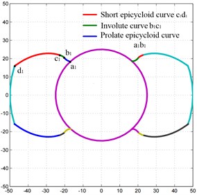
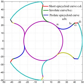
When the main and slave screw rotor of the double screw pump is engaged, the screw groove is divided into several relatively sealed closed cavities, which requires the screw type line to meet the needs of continuous tangent. The end surface line and engagement line of the double screw pump A-type screw rotor are shown in Fig. 1. Part of the profile line of the end face of the active screw is composed of the involute tangent to the long epicycloid and the short epicycloid . In the design process, the angle of is determined, and the rest of the profile lines can be obtained symmetrically about the and axes.
In the design of the end face profile of the driven screw, the driving screw rotor rolls around the driven screw rotor on the pitch circle, the driven screw rotor is the main body, and the order of the curves does not change. Therefore, its equation is the exchange of each angle label “2” and “1” of the driving screw rotor end face profile equation, that is, the tooth profile curve of the corresponding driven screw helical surface.
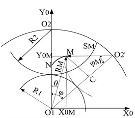
The tooth profile curve of the helical end face is shown in Fig. 2. NM represents the trajectory formed by each tooth profile curve in the process of rotation, it can be seen from the Fig. 2(a), (b) and (c) that the positions of the starting points of each tooth profile curve are different, in order to satisfy that the involute is both the end point of the prolate epicycloid and the curtate epicycloid, it is required to specify the common coordinate system of the curve and transform its curve equation.
Fig. 1End face profile and meshing line of type a screw rotor of twin screw pump
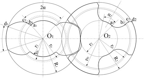
Fig. 2Tooth profile curve of spiral end face
a) Prolate epicycloid
b) Involute
c) Curtate epicycloid
2.1. Curve equation derivation
The curve is a long epicycloid, the pitch circle with the radius of the helical end face of the driven screw is as the moving circle, and when the pitch circle with the radius of of the helical end face of the driving screw is rolling along the fixed circle, the locus of a point outside the tooth top circle of the helical end face of the driven screw is a long epicycloid. It can be seen from Fig. 2(a) that the coordinates of any point m of the long epicycloid are:
where is the rotation angle of the moving circle , is the corresponding rotation angle of the fixed circle , is the distance between the moving circle and the fixed circle , that is, [16], is the length of the moving circle to the distance of any point on the prolate epicycloid:
there: is the Spiral-gear addendum coefficient of the driven screw, which is the toothed angle of the end face when helical meshing.
The equation for to be obtained from is:
From , the tooth pole angle of the long epicycloid can be obtained as:
2.2. Curve equation derivation
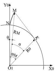
The involute developed by the base circle radius on the spiral end face of the driving screw is the involute.
From Fig. 2(b), it can be seen that the equation of the segment of the involute is:
where: is the involute polar angle, is the involute meshing angle.
From Fig. 2(b), it can be known that the tooth pole angle of the involute segment is:
2.3. Curve equation derivation
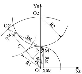
The segment is a curtate epicycloid, and the pitch circle with a radius of on the helical end face of the driven screw is used as the moving circle, when rolling along the pitch circle whose fixed circle is the radius of the spiral end face of the active screw, the track of a point in the addendum circle of the tooth profile of the spiral end face of the driven screw is the prolate epicycloid.
From Fig. 2(c), it can be known that the coordinates of any point on the curtate amplitude epicycloid are:
Variable substitution of Eq. (7) combined with Fig. 1 to obtain Equation of the segment:
The equation to get from is:
From , the toothed polar angle of the prolate epicycloid is:
2.4. Coordinate system conversion of the curve equations of each section
It can be seen from Fig. 2 that the points of the above 3 curve profiles are in their respective coordinate systems. The tooth profile curve of the screw pump rotor requires a combination of multi-segment curves, and the position of the starting point of each segment of the curve and the polar angle of the tooth profile are different, in order to connect these three curves smoothly, they need to be converted to the same coordinate system. After rotating the coordinates, the angle between the arbitrary point and the axis on the tooth profile curve changes from the original to , Therefore, the equations of the curves , and after the coordinate system transformation are shown in Eq. (11) to (13):
3. Screw rotor end surface type line optimization
The basic parameters of type A screw rotor of double screw pump are shown in Table 1.
Table 1Twin screw pump type A screw rotor screw parameters
Parameter name | Numeric value /mm |
Active screw pitch circle diameter / mm | 30 |
Driven screw pitch diameter / mm | 45 |
Active screw addendum circle diameter / mm | 50 |
Center distance / mm | 75 |
Lead / mm | 75 |
Using Matlab to program Eq. (11) to (13), the end face profiles of the main and driven screws of the A-type screw rotor of the twin-screw pump are shown in Fig. 3.
Fig. 3Curve of driving and driven screw rotor under Matlab
a) Active screw
b) Driven screw
Through the curve combination composed of prolate epicycloid, involute and curtate epicycloid, the shortcoming of the helical tooth profile of the cycloid meshing driven screw at the sharp angle at the tip circle can be solved easily. However, it is found that there is a sharp point at the junction of the involute and the curtate epicycloid in the end face profile of the driven screw, as shown in Fig. 4(a). In order to reduce the wear of the screw, increase the service life of the screw and ensure the transmission of the medium by the closed cavity in the meshing area between the screws, based on the above profile, this paper uses the arc transition method to correct the sharp point of the driven screw and optimize the curve of the driven screw, as shown in Fig. 4(b). In area a of Fig. 4, it can be seen that the arc transition is carried out at the tooth root circle of the optimized driven screw, and in area B, a smooth arc is obtained by optimizing the tooth tip of the driven screw.
Fig. 4Driven screw profile before and after optimization
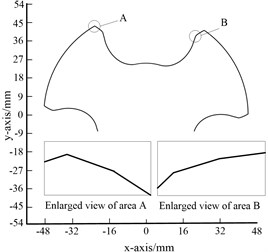
a) Before optimization
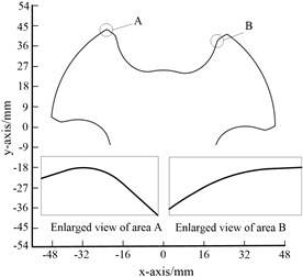
b) After optimization
4. Numerical simulation analysis of internal flow channel in double-screw pump
4.1. Geometric model of A screw rotor of double screw pump
After the partial profiles of the driving and driven screws of the A-type screw rotor of the twin-screw pump generated by MATLAB programming, the coordinate values of each point are imported into UG (Unigraphics NX) for the command of data fitting. When the rotation lead is 75 mm and the length of the screw is 300 mm, the helicoid is swept, the solid model of the active and driven screws is obtained as shown in Fig. 5.
4.2. Establishment of the numerical simulation model
In UG, the three-dimensional fluid model of the twin-screw pump is obtained by performing Boolean operations on the three-dimensional model of the twin-screw pump, as shown in Fig. 6(a). The model is imported into the Fluent module for meshing, and the flow field mesh model of the twin-screw pump with 490,000 nodes and 2.37 million elements is in the form of unstructured tetrahedral mesh, as shown in Fig. 6(b).
Fig. 5Entity model of A-type screw rotor of twin-screw pump: 1 – drive screw rotor; 2 – active screw rotor
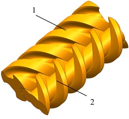
Fig. 6The finite element model of the flow field of the twin-screw pump: 1 – active screw inner surface; 2 – outer wall; 3 – active screw speed ω1; 4 – driven screw speed ω2; 5 – outlet; 6 – driven screw inner surface; 7 – inlet
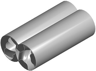
a) Flow field model established in UG
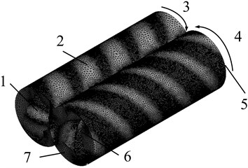
b) Grid divided in the flow field
When the geometric model of the A-type screw rotor of the twin-screw pump is imported into Ansys for the analysis and calculation of the flow field of the flow channel, five boundary conditions need to be set: namely, the exit and entrance end faces, the outer wall of the driving screw, and the inner surface of the active and driven screws flow channels [19-21]. The inlet boundary of the twin-screw pump is set as the pressure inlet, and the outlet boundary is set as the pressure outlet; the pressure at the inlet is , the pressure at the outlet is , and the pressure difference is .
Select the midpoint of the flow channel as the coordinate origin, and the liquid outflow direction is along the positive axis. Referring to the assumption that there is no slippage on the wall of the runner, the boundary conditions on the outer surfaces of the active and driven screws are the circumferential rotation speeds, taking the rotation speed of the master screw as 1500 r/min, the driving screw rotates in the opposite direction to the driven screw, and the transmission ratio of the driving screw and the slave screw is 3:2 (the number of teeth of the driving screw rotor is 2, the number of teeth of the driven screw rotor is 3, and the transmission ratio is the inverse ratio of the number of teeth); Take the pressure difference of the flow channel as 2.4 MPa. On the inner surface of the flow channel, its speed is zero, that is, 0 m/s.
4.3. Numerical simulation results
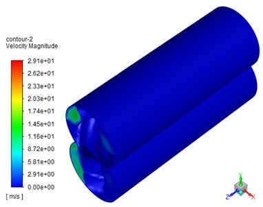
pressure distribution cloud diagram is shown in Fig. 7(a). It can be seen that the pressure at the inlet end is the lowest. With the continuous increase of the cavity volume, the pressure increases step by step along the axial direction of the screw, and the screw is blocked in its effective area. It is divided into 4 sealing chambers with different pressure levels, and the distribution of the meshing line has the same distribution characteristics as the boundary lines of different pressure levels of the sealing chambers. In general, the pressure changes in stages, and the pressure increases gradually from the inlet to the outlet, and the pressure in the meshing area is complicated; it can be seen from Fig. 7(b) that the outer wall speed is almost zero, and the speed is mainly concentrated at the meshing gap between the main and driven screws, indicating that the liquid flows from the inlet to the outlet.
From Fig. 7(c), it can be seen that the speed at the gap channel between the driven screw and the main and driven screws is higher, and the speed at the driving screw and its root is lower, near the meshing area. The vortex is generated, which is due to the effect of the volume pressure difference, and the rotation direction of the master and slave screws is inconsistent, resulting in a change in the direction of the liquid in the meshing area, forming a vortex. It can be seen from Fig. 7(d) that the velocity on the left side of the inlet section is larger than that on the right side, and higher than that in other areas. This is because the driven screw rotates clockwise, the driving screw moves clockwise, and the fluid is positively sheared on the left. The fluid is subjected to a positive shear force on the left, and the fluid is extruded toward the outlet.
Fig. 7Runner field velocity and pressure field
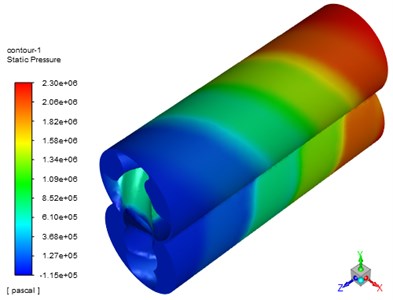
a) Pressure distribution cloud map
b) Overall speed cloud map
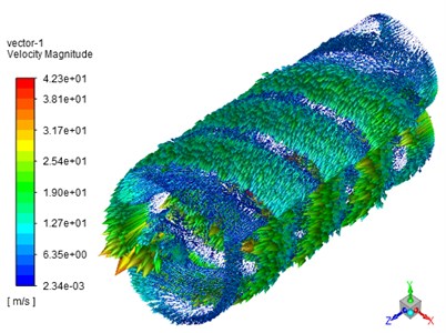
c) Overall speed cloud map
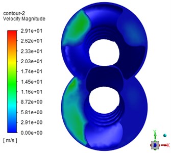
d) Cross-sectional speed cloud map of the inlet
4.4. Analysis of the influence of screw center distance on flow field and pressure field of twin-screw pump before and after optimization at different speeds
The center distance of the main and driven screws is an important parameter in the twin-screw pump. In order to further study and optimize the working performance of the twin-screw pump before and after, under the condition of constant inlet and outlet pressure difference, the influence of changing the center distance of twin-screw pump and the speed of active screw rotor on the pressure field and speed field of twin-screw pump fluid is analyzed.
Set the inlet and outlet pressure difference as 2 MPa; the rotation speed of the active screw is 1500-2100 r/min, the interval is 100 r/min; the center distance is set to 75.00-75.40 mm, and the interval is 0.05 mm. The relationship between the center distance and the maximum pressure value of the flow field and the maximum velocity value of the flow field is obtained from the analysis, as shown in Fig. 8.
Fig. 8Numerical curves of the flow field and pressure field of the twin-screw pump before and after optimization
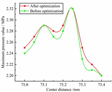
a) Center distance and flow channel pressure curve
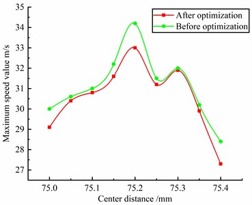
b) Center distance and flow channel velocity curve flow channel
It can be seen from Fig. 8(a): under the same pressure difference, with the continuous increase of the center distance, the maximum pressure value of the flow field fluctuates slightly up and down, and reaches the maximum value when the center distance is 75.25 mm; After optimization, the maximum pressure increases by 1 % compared with that before optimization. This is because the inter tooth clearance between the optimized screw rotors becomes smaller, which reduces the backflow of liquid and increases the volumetric efficiency in the pump.
It can be seen from Fig. 8(b): under the same pressure difference, with the continuous increase of the center distance, the maximum velocity of the flow field first increases and then decreases, and reaches the maximum value when the center distance is 75.25 mm; After optimization, the maximum speed is reduced by 3.5 % compared with that before optimization. This is because the speed of the liquid in the pump at the tooth root circle is reduced, the impact on the inner helical surface of the screw rotor is reduced during the liquid movement, the wear inside the screw rotor is reduced, and the service life of the screw rotor is increased; At the same time, the working efficiency of the whole twin-screw pump is guaranteed. In order to improve the working performance of twin-screw pump, the meshing clearance should be reasonably selected during machining and assembly.
5. Modal analysis of the screw rotor
The special structure of the twin-screw pump and the characteristics of the closed sealed cavity make the simulation of its internal vibration complicated. In this paper, the fluid-structure coupling method is used to calculate the modes of the twin-screw pump without prestress and under the action of fluid-structure coupling, respectively, and compare the calculation results. The variation law of vibration of twin-screw pump under working conditions and its influence on working characteristics are studied.
5.1. Modal analysis and calculation
The main research on the twin-screw pump is the stress and deformation of the screw rotor during the operation of the pump. The natural frequency is determined by the properties of the structure itself. When the modal analysis of the screw rotor of the twin-screw pump is performed, the structure needs to be simplified. According to D’Alembert’s theory, the dynamic equations of the main and driven screw rotors in the twin-screw pump are obtained as:
where is the mass matrix, is the damping matrix, is the stiffness coefficient matrix, is the screw acceleration vector, is the screw velocity vector, is the displacement vector, and is the force vector.
The effect of external load and damping are ignored in the analysis without prestressing state, then the simplified equation is:
It can be seen from Eq. (12) that:
where is the n-order eigenvector, is the vibration frequency of the vector , is the time variable, and is the time constant under the initial condition.
From Eqs. (15) and (16), it can be known:
Eq. (14) has a non-zero necessary and sufficient condition as:
When the order of and is , and is the eigenvalue, the eigenvectors of the -th order vibration frequency and the -th order mode can be obtained.
5.2. Establishment of finite element model
According to the parameters in Table 1, the three-dimensional solid models of the master and driven screw rotors are established as shown in Fig. 9, and the mesh model obtained by dividing the master and driven screw rotors by tetrahedral meshes is shown in Fig. 10.
The finite element software ANSYS is used to carry out modal analysis on the main and driven screws. The material of the screw is 38CrMoAl with high yield strength and wear resistance, and its performance parameters are shown in Table 2.
Table 238CrMoAl material parameters
Performance parameters | Density / (kg/m3) | Elastic modulus / Pa | Poisson’s ratio | Yield strength / MPa | Tensile strength / MPa |
Parameter value | 7800 | 2.1×10⁹ | 0.3 | 980 | 835 |
5.3. Modal analysis of the screw in the free state
Set the boundary conditions for the screw mesh model that has been completed, fix its four ends, and only retain the degree of freedom of the screw rotor to rotate in the axial direction. The first 6-order modes of the simulated master and driven screw rotors are shown in Fig. 11.
Fig. 9The model of the main and the driven screw rotors: 1 –driven screw rotor; 2 – active screw rotor
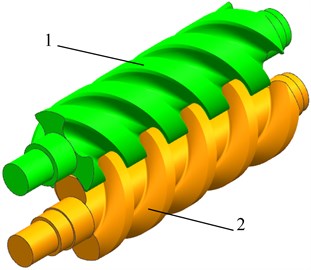
Fig. 10Mesh model of master and slave screw rotors
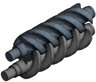
Fig. 11Mode shapes of the first six orders of the screw rotor without prestress
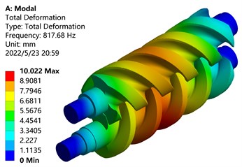
a) First-order mode shape
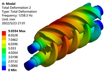
b) Second-order mode shape
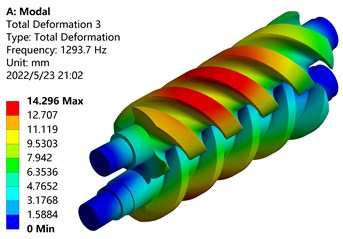
c) Third-order mode shape
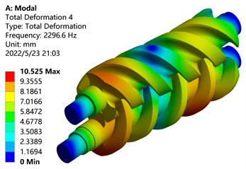
d) Four-order mode shape
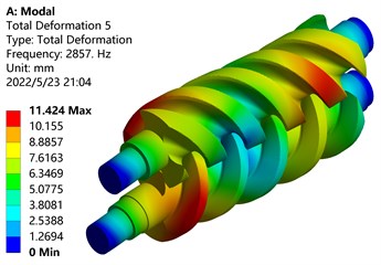
e) Five-order mode shape
f) Six-order mode shape
From the modal analysis cloud diagram in Fig. 11, it can be seen that: The first-order mode shape is mainly manifested in the bending vibration along the -axis of the screw parts of the main and driven screw rotors, the maximum deformation position occurs on the tooth surface of the driving screw, and the deformation of the driven screw is small, Because the deformation part is far away from the shaft end, the disturbance is large and the deformation amount is large; The second-order mode shape is mainly manifested in the bending vibration along the -axis of the screw parts of the main and driven screw rotors, and the maximum deformation position occurs on the tooth surface of the screw rotor near the front end; The third-order mode shape is mainly manifested in the torsional vibration of the screw parts of the main and driven screw rotors around the center of the -axis, and the maximum deformation position occurs outside the screw rotors; The fourth-order mode shape vibrates in waves on the -axis, and the maximum deformation position occurs on the tooth surface of the active screw rotor near the shaft end; The fifth-order mode shape vibrates in a wave-like manner on the -axis, and the maximum deformation position occurs on the tooth surface of the screw rotor near the shaft end; The sixth-order mode shape is mainly manifested in the torsional vibration of the screw parts of the main and driven screw rotors around the center of the -axis, and the torsional directions of the main and driven screw rotors are opposite, the outer end near the shaft deforms the most.
Table 3 lists the frequency and amplitude of the first six modes of the screw rotor. It can be found from the table that with the increase of the mode order, the frequency of the screw rotor increases, and the frequencies of the second and third orders are similar. The amplitudes of the first and fourth orders are similar.
Table 3The free modal analysis results of the screw rotor
Order | First-order | Second-order | Third-order | Four-order | Five-order | Six-order |
Frequency / Hz | 817.68 | 1258.30 | 1293.70 | 2296.6 | 2857.10 | 2945.20 |
Amplitude / mm | 10.022 | 9.059 | 14.296 | 10.525 | 11.424 | 15.377 |
5.4. Modal analysis of screw under fluid-structure interaction
The internal flow field of the twin-screw pump is simulated and analyzed by the CFD method. The boundary conditions are: the internal flow medium is selected from water, and the calculated temperature of the fluid is 313.16 K. Basic parameters of the fluid at 313.16 K: Density 992 kg/m3, Dynamic viscosity 6.56×10⁻³ Pa·s, Thermal conductivity 0.635 W/(m·K), Specific heat capacity 4174 J/(kg·K).
Through the Static Structural module in ANSYS Workbench, the pressure calculated by the internal flow field of the twin-screw pump is introduced as an external load to the surfaces of the main and driven screw rotors respectively. The supporting method of the main and driven screws of the twin-screw pump is also to fix its four ends, and only retain the freedom of the screw rotor to rotate in the axial direction. The active screw rotor is connected with the motor output shaft to input power, the active screw rotor rotates around the axis, and the active screw rotor drives the driven screw rotor to rotate. Therefore, radial and axial constraints are set at the connection between the main and driven screw rotors and their respective bearings.
The pressure load in the pump is applied to the surfaces of the main and driven screw rotors respectively, and the effect is shown in Fig. 12. As shown in Fig. 13, the maximum deformation under the action of fluid-structure interaction is 0.010026 mm, and the maximum deformation occurs at the shaft end of the active screw rotor.
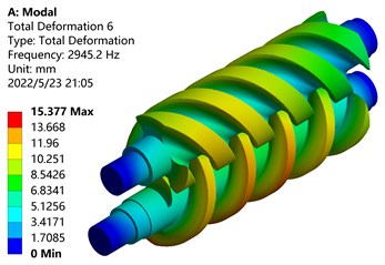
It can be seen from Fig. 14 that after the fluid-structure coupling force is applied, the change trends of the modal frequencies of each order are basically the same, but the magnitudes of the frequencies and amplitudes change. The frequency change is due to the deformation of the main and driven screw rotors caused by the fluid pressure, which causes the screw rotors to change, so the frequency is higher than the original frequency.
Table 4 shows the comparison of the modal analysis results of the main and driven screw rotors under two different working conditions. It can be found from the table that with the increase of the modal order, the frequency of the screw rotor becomes higher, and only the amplitude of the first order is similar. After the fluid-structure coupling force is applied, the third-order amplitudes of the main and driven screw rotors decrease, and the remaining amplitudes increase. The reason for this phenomenon is that the deformation of the main and driven screw rotors by the fluid pressure is not the same as the deformation direction caused by the vibration, which cancels out part of the deformation.
Fig. 12Screw fluid pressure loading
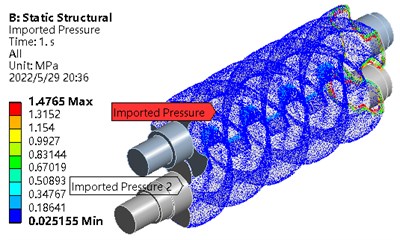
Fig. 13Fluid-structure interaction
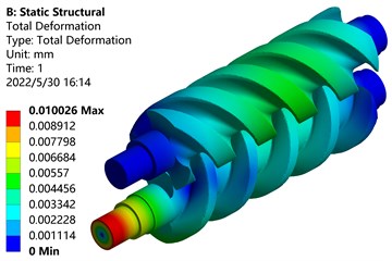
Fig. 14Mode shapes of the first 6 orders of screw rotor under the action of fluid-structure interaction
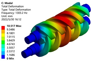
a) First-order mode shape
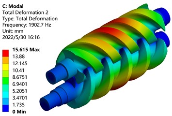
b) Second-order mode shape
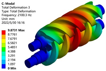
c) Third-order mode shape
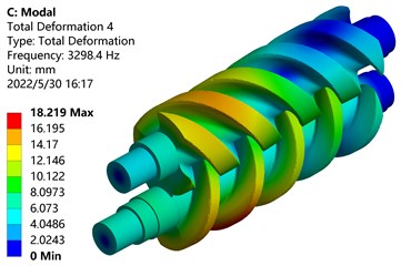
d) Four-order mode shape
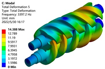
e) Five-order mode shape
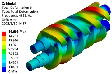
f) Six-order mode shape
It can be seen from Fig. 11 and Fig. 14 that the amplitudes of the main and driven screw rotors without prestress and fluid-structure coupling are shown in Table 5.
Draw part of the data in Table 4 and the data in Table 5 as a broken line, as shown in the picture above. In Fig. 15, the frequency change rules under the action of no prestress and fluid-structure coupling are basically the same. The frequencies of each order of the main and driven screw rotors are in an increasing relationship, and the frequency of the third order changes greatly. Compared with no prestress, the frequency under the action of fluid-structure coupling increases by 62.35 %; The frequency change of the fifth order is smaller, which is 18.90 % higher than that of the first order; the frequency increase of the sixth order is the largest, but the percentage of frequency increase is lower.
Table 4Modal analysis of screw rotor without prestress and fluid-structure interaction
Order | First-order | Second-order | Third-order | Four-order | Five-order | Six-order |
Frequency / Hz | 817.68 | 1258.30 | 1293.70 | 2296.6 | 2857.10 | 2945.20 |
Amplitude / mm | 10.022 | 9.059 | 14.296 | 10.525 | 11.424 | 15.377 |
Frequency / Hz | 1303.20 | 1902.70 | 2100.30 | 3298.40 | 3397.20 | 4199.00 |
Amplitude / mm | 10.517 | 15.615 | 9.873 | 18.219 | 14.388 | 16.606 |
Table 5Amplitudes of the driving and driven screw rotors without prestress and fluid-structure interaction
Order | First-order | Second-order | Third-order | Four-order | Five-order | Six-order |
Driving screw amplitude without prestress / mm | 10.022 | 8.412 | 13.274 | 15.525 | 11.424 | 15.377 |
Amplitude of driven screw without prestress / mm | 8.590 | 9.059 | 14.296 | 9.773 | 10.608 | 14.278 |
Driving screw amplitude under fluid-structure interaction / mm | 9.766 | 15.615 | 9.650 | 18.219 | 14.388 | 15.520 |
Amplitude of driven screw under fluid-structure interaction / mm | 10.517 | 14.550 | 9.873 | 15.616 | 12.859 | 16.606 |
Fig. 15Frequency variation of screw rotor under two conditions
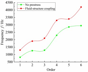
Fig. 16Amplitude change of screw rotor under two conditions
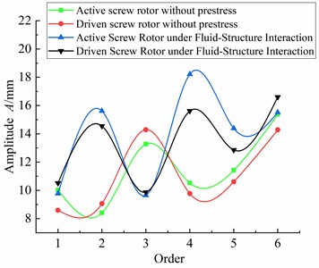
In Fig. 16, the amplitudes of the main and driven screw rotors under the action of no prestress and fluid-structure coupling both rise in waves, and the variation law of the amplitudes of the main and driven screw rotors under the action of no prestress and fluid-structure coupling is inconsistent; The amplitude of the main and driven screw rotors under the fluid-structure interaction decreases rapidly in the third-order vibration mode and is lower than the amplitude without prestress. The reason is that the deformation of the main screw rotor and the driven screw rotor caused by the fluid pressure is basically opposite to the deformation direction caused by the vibration, which cancels part of the deformation effect of each other. In the absence of prestress, the amplitude of the active screw rotor is smaller than that of the driven screw rotor except for the second and third vibration modes, and the amplitudes of the other vibration modes are larger than the former. Under the action of fluid-structure interaction, the amplitude of the active screw rotor is smaller than that of the driven screw rotor except for the 3rd and 6th vibration modes, and the amplitudes of the other vibration modes are larger than the former. It can be seen that the amplitude of the driving screw rotor is larger than that of the driven screw rotor in most mode shapes. The reason is that the meshing gap causes collision between the main and driven screw rotors, and the difference in structure makes the inter-tooth volume of the driving screw larger, these two factors cause the amplitude of the driving screw rotor to be larger than that of the driven screw rotor in most mode shapes.
6. Conclusions
1) The cusp and curve of the screw rotor are optimized by the arc transition method. The optimized screw rotor changes from point contact to surface contact during the movement of the screw rotor, which reduces the wear between the screw rotor.
2) Through the simulation analysis of the flow field of the screw rotor of the optimized twin-screw pump, the results show that the maximum pressure after optimization increases by 1 % compared with that before optimization. With the continuous increase of the center distance, the maximum pressure of the flow field fluctuates slightly up and down; The maximum velocity after optimization is 3.5 % lower than that before optimization. Through simulation, it is found that the best meshing gap is when the center distance is 75.25 mm. Under this gap, the impact on the inner helical surface of the screw rotor during the liquid movement is reduced, the wear inside the screw rotor is reduced, and the service life of the screw rotor is increased.
3) Under free conditions, with the increase of the modal order, the frequencies of the main and driven screw rotors increase, and the frequencies of the second and third orders are similar, and the amplitudes of the first and fourth orders are similar.
4) After the fluid-structure coupling force is applied, the frequencies of the main and driven screw rotors also increase with the increase of the modal order. The frequency change is due to the deformation of the main screw rotor and the driven screw rotor caused by the fluid pressure, which causes the screw rotor to change, so the frequency is higher than that without prestress. The variation law of the amplitudes of the main and driven screw rotors under the action of no prestress and fluid-structure coupling is inconsistent; The amplitude of the main and driven screw rotors under the fluid-structure interaction decreases rapidly in the third-order vibration mode and is lower than the amplitude without prestress. The reason is that the deformation of the main screw rotor and the driven screw rotor caused by the fluid pressure is basically opposite to the deformation direction caused by the vibration, which cancels part of the deformation effect of each other.
References
-
Z. Shen, “Profile design method of twin-screw compressor rotors based on the pixel solution,” Mathematical Problems in Engineering, Vol. 2020, pp. 1–7, Sep. 2020, https://doi.org/10.1155/2020/2653517
-
Z. Liu, Q. Tang, N. Liu, P. Liang, and W. Liu, “A novel optimization design method of form grinding wheel for screw rotor,” Applied Sciences, Vol. 9, No. 23, p. 5079, Nov. 2019, https://doi.org/10.3390/app9235079
-
J. Wang, M. Wu, F. Cui, Q. Tan, and Z. Wang, “Research of a novel eccentric involute rotor and its performance analysis for twin-screw vacuum pumps,” Vacuum, Vol. 176, p. 109309, Jun. 2020, https://doi.org/10.1016/j.vacuum.2020.109309
-
J. Wang, S. Wei, R. Sha, H. Liu, and Z. Wang, “Design methodology of a new smooth rotor profile of the screw vacuum pump,” Vacuum, Vol. 159, pp. 456–463, Jan. 2019, https://doi.org/10.1016/j.vacuum.2018.10.064
-
X. He, C. Pan, M. Wu, X. Ji, and R. Zhang, “A twin-screw rotor profile design and computational fluid dynamic simulation method,” Materials Research Innovations, Vol. 19, No. sup8, pp. S8–721-S8-726, Nov. 2015, https://doi.org/10.1179/1432891715z.0000000001879
-
D. Yan, A. Kovacevic, Q. Tang, S. Rane, and W. Zhang, “Numerical modelling of twin-screw pumps based on computational fluid dynamics,” Proceedings of the Institution of Mechanical Engineers, Part C: Journal of Mechanical Engineering Science, Vol. 231, No. 24, pp. 4617–4634, Dec. 2017, https://doi.org/10.1177/0954406216670684
-
X. M. He, S. P. Ye, J. Tong, M. Wu, and R. Zhang, “Design of twin screw compressor rotor profiles based on B-spline curve,” (in Chinese), Machine Design and Research, Vol. 31, No. 5, pp. 133–137, 2015, https://doi.org/10.13952/j.cnki.jofmdr.2015.0203
-
X. H. Wu, W. H. Cheng, and B. F. Zhang, “Optimization design of screw rotor with automatic dynamic balance of a screw vacuum pump,” (in Chinese), Journal of Vibration and Shock, Vol. 19, pp. 144–149, 2015, https://doi.org/10.13465/j.cnki.jvs.2015.19.023
-
G. J. Shi, X. M. He, and R. Zhang, “Rong research on development of the design system of twin screw compressor rotor profiles,” (in Chinese), Compressor Technology, Vol. 5, pp. 6–13, 2018, https://doi.org/10.16051/j.cnki.ysjjs.2018.05.002
-
X. Feng, F. L. Meng, and J. Q. Yang, “Optimization design on rotor profile of down-hole twin-screw pump,” (in Chinese), Mechanical Engineering and Automation, Vol. 4, pp. 9–15, 2018, https://doi.org/10.3969/j.issn.1672-6413.2018.04.004
-
B. W. Zhu, Y. Q. Zhao, and Z. Liu, “Numerical simulation of flow field dynamic characteristics of three-screw pump,” (in Chinese), Machine Tool and Hydraulics, Vol. 48, No. 16, pp. 113–120, 2020, https://doi.org/10.3969/j.issn.1001-3881.2020.16.024
-
G. O. Shi and C. Han, “Parametric model for single screw pump based on grip,” (in Chinese), Machine Tool and Hydraulics, Vol. 8, pp. 111–113, 2013, https://doi.org/10.11832/j.issn.1000-4858.2013.08.032
-
M. Y. Zhi, Z. F. Li, and X. D. Wan, “Analysis of thermal structure characteristics of twin screw compressor,” (in Chinese), Machine Tool and Hydraulics, Vol. 45, No. 9, pp. 172–179, 2021, https://doi.org/10.11832/j.issn.1000-4858.2021.09.024
-
Y. Q. Zhao, B. W. Zhu, and Z. Liu, “Analysis of fluid solid coupling characteristics of three screw pump,” (in Chinese), Machine Tool and Hydraulics, Vol. 6, pp. 70–77, 2020, https://doi.org/10.11832/j.issn.1000-4858.2020.06.011
-
G. J. Wu, F. Zhang, and J. Zhu, “Modal analysis of screw rotor of twin-screw expander,” (in Chinese), Mechanical, Vol. 43, No. 11, pp. 4–9, 2016, https://doi.org/10.3969/j.issn.1006-0316.2016.11.002
-
Z. W. Zhang, W. D., Shi, and D. S. Zhang, “Modal analysis of rotor components of LNG cryogenic submersible pump based on heat-fluid-structure coupling,” (in Chinese), Journal of Drainage and Irrigation Machinery Engineering, Vol. 37, No. 3, pp. 211–215, 2019, https://doi.org/10.3969/j.issn.1674-8530.17.0112
-
L. L. Qi, “Stress and modal analysis of bidirectional pump vane,” (in Chinese), Yangzhou University, 2015.
-
Y. J. Chen, Y. Zheng, and K. Kan, “Modal analysis in water of axial flow pump rotor system,” (in Chinese), Journal of Drainage and Irrigation Machinery Engineering, Vol. 35, No. 2, pp. 126–132, 2017, https://doi.org/10.3969/j.issn.1674-8530.15.0278
-
F. Li, Y. Li, and X. Li, “Numerical investigation of internal flow field in a low – specific speed centrifugal pump at low flow rate,” Journal of Mechanical and Electrical Engineering, Vol. 32, No. 11, pp. 1438–1442, 2015, https://doi.org/10.3969/j.issn.1001-4551.2015.11.009
-
Q. Ran, T. Wang, and B. Liu, “Dynamic characteristic analysis for rotor system of swash-plate axial piston pump,” (in Chinese), Hydraulics and Pneumatics, Vol. 45, No. 10, pp. 134–142, 2021, https://doi.org/10.11832/j.issn.1000-4858.2021.10.019
-
Z. Lu, J. Wang, and Q. Li, “Influence of material properties on rotor structure of twin screw compressor,” (in Chinese), Hydraulics and Pneumatics, Vol. 45, No. 6, pp. 69–76, 2021, https://doi.org/10.11832/j.issn.1000-4858.2021.06.011
Cited by
About this article

This research was funded by the Shaanxi Provincial Natural Science Basic Research Program Project (2019JM-466) and the Shaanxi Provincial Key Laboratory of Industrial Automation Open Project (SLGPT2019KF01-19) and the Shaanxi University of Technology Graduate Innovation Fund Project (SLGYCX2122).
The datasets generated during and/or analyzed during the current study are available from the corresponding author on reasonable request.
The authors declare that they have no conflict of interest.
