Abstract
To accommodate special applications where installation space is limited and noise and vibration requirements are high, a new triple screw pump structure was proposed, which was integrated into a servo motor. The design optimizes the profile of the master and slave screws of the embedded triple screw pump. The temperature and pressure fields of the embedded triple screw pump, as well as the heat transfer and pressure distribution between the fluid in the pump and the screw, were investigated through a thermal-fluid-structure approach. The deformation and stresses of the screw were compared for three operating conditions: temperature loading, pressure loading, and thermal-fluid-structure coupling. The results show that the deformation and stresses in the screw tended to increase with increasing pressure and temperature and the pressure load caused more significant deformation and stresses in the screw than the temperature load. The screw deformation caused by pressure loading was found to be the main factor affecting the thermal-fluid-structure coupling. The screw deformation after coupling was smaller than the sum of the screw deformation caused by individual temperature and pressure loads, and the stress values were the same. The results indicate that the coupling action weakens the deformation and stresses in the master and slave screws.
1. Introduction
The vibration and noise of hydraulic pumps can significantly affect the overall performance, reliable operation, and service life of the hydraulic systems. Moreover, the noise causes fatigue and adverse impact on the health of the people operating the system. Thus, systematic explorations on the requirements of small installation space with low noise and vibration for submarine hydraulic pumps are highly demanded. Herein, a new embedded triple screw pump structure was proposed and the core of a servo motor was embedded in it, thus the integrated system constitutes a new type of electric pump. The triple screw pump belongs to the same class of screw pumps as the twin-screw pump. Compared to piston pumps, it offers outstanding advantages in terms of noise, vibration, and flow stability.
Screw pumps, screw air compressors, and extruders are equivalent to volumetric mechanical products that have similar structures and key components. In recent years, many scholars have used computational fluid dynamics (CFD) simulations and tests to carry out the related research. Using a twin-screw pump as the object of study, the contact line equations for the screw tooth profile and spiral surface were derived and the flow, pressure, and velocity fields were simulated numerically [1, 2]. Moreover, the flow characteristics of the fluid in the pump and the process of cavitation formation were investigated under different speeds and discharge pressures [3, 4]. The temperature and pressure distribution at multiple points of the progressive cavity pump was obtained experimentally and the effect of screw deformation on the leakage and volumetric efficiency of the progressive cavity pump was analyzed [5, 6]. At the same time, the gas-liquid mixed transportation process of the twin-screw pump was simulated by the thermo-fluid-solid coupling method [7]. Previous research on progressive cavity pumps has focused on the flow field, pressure field, and structural deformation, and the results obtained from heat transfer and fluid pressure calculations within the pump do not match with the requirements of the actual situation. Consequently, there has been relatively little research on the fluid-structure coupling of spiral rotors. Therefore, the method of fluid-structure coupling analysis is gaining progressively more attention in engineering practice. A three-dimensional (3D) transient hydrodynamic mesh was established with a twin-screw compressor as the research object to improve the simulation accuracy [8-10].
A parametric structure was established to study the effect of different operating conditions on the rotor temperature field [11, 12], while the pressure distribution of the flow field in the cavity of the air compressor was studied experimentally and the simulation results were verified [13]. The oil injection temperature distribution model of the screw compressor rotor was established and the thermal deformation of the screw rotor was estimated. The thermal deformation and energy loss of the screw rotor were simulated, and the heat transfer model of the screw rotor and the thermal coupling of the compressed gas were also established to solve the conjugate heat transfer problem of the compressor [14-16]. This was followed by a coupled thermo-hydraulic simulation of the rotor temperature and thermal deformation of the rotor and housing of the screw expander [17]. Based on CFD theory, a steady-state numerical simulation of a twin-screw kneader was carried out to investigate the effect of increasing rotor pitch or decreasing clearance on the viscosity dissipation rate of a twin-screw extruder [18-20]. The screw is the main component in a screw machine product and the structural deformation of the screw under the action of the flow field determines the overall stability and volumetric efficiency of the screw. The coupled heat-flow-structure approach is; therefore, able to accurately reflect the interaction between fluid and structural deformation.
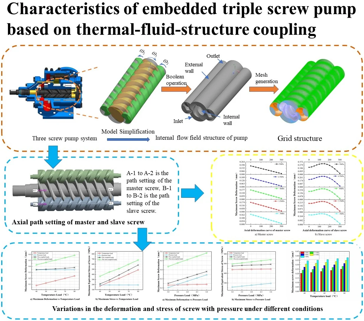
In this study, a 3D numerical simulation of the flow field and heat transfer in an embedded triple screw pump was implemented by using Fluent® software. Based on the calculation results, the pressure and temperature loads on the screw surface were determined. The conversion of fluid temperature, pressure load, and screw model structure was achieved using a Workbench. The thermal-fluid-structure coupling method was used to study the temperature field and pressure field distribution of the embedded triple screw pump. The pressure and temperature of the flow field and the deformation and equivalent stress of the solid structure under different working conditions were calculated. The mechanical characteristics of the master and slave screws under coupled and uncoupled loads were compared. Finally, the deformation and stress of the screw under temperature load, pressure load, and thermal fluid solid coupling were compared and systematically analyzed.
2. Theoretical analysis
In the process of obtaining the fundamental equations of fluid motion, the continuity equation, the momentum equation, and the energy equation of the physical principles should be included.
Continuity equation is expressed as Eq. (1) as follows:
The vector form is given by Eq. (2):
When the fluid is incompressible viscous fluid, the fluid density () is constant, and therefore, Eq. (2) can be written as Eq. (3):
where is the divergence, given by the correlation: .
Momentum equation is given by Eq. (4):
where is the density; kg m–3, is the Hamiltonian operator; is the velocity vector; , , and are components of velocity in the , , and directions, respectively, m s–1; is the kinematic viscosity, m2 s–1; is the static pressure, Pa; and , , and are components of stress in the , , and directions, respectively, MPa.
In general, the fluid energy represents the sum of internal energy, kinetic energy, and potential energy. According to the thermodynamics, a relationship exists between the internal energy and temperature. Therefore, the energy conservation equation of the fluid is written as Eq. (5):
The expanded form is given by Eq. (6):
where is the specific heat capacity, (kg·K)–1; is the thermodynamic temperature, K; is the thermal conductivity of the fluid, (m·K)–1; is the internal heat source of the fluid; and is the viscous dissipation term.
The equation of structural motion is given by Eq. (7):
where is the mass matrix, is the damping matrix, is the stiffness coefficient matrix, is the displacement vector, is the velocity vector, is the acceleration vector, and is the force vector comprised of the gravitational force, centrifugal force, and flow field pressure.
The heat transfer equation is given by Eq. (8):
where is the displacement matrix, is the heat capacity matrix, is used to distinguish the different items of different media, is used to study the outer boundary of the area, is the heat conduction matrix, is the heat transfer coefficient, n is the outer normal vector, and is the function of the interaction time of the external environment with the system.
3. Thermal-fluid-structure coupling finite element model
3.1. Structure of the embedded triple screw pump
Fig. 1 shows the main body of the system, which consists of a triple screw pump, a permanent magnet synchronous motor, and a synchronous gear set. The motor rotor is connected to the master and slave screws of the pump through a gear set, making full use of the space between the motor and the pump and reducing the number of parts and overall volume. The triple screw pump can be directly embedded in the motor stator iron core, and it adopts a new type of axial flow structure with one end as the suction end and the other as the discharge end.
Fig. 1Overall schematic illustration of the embedded triple screw pump
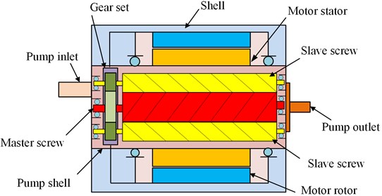
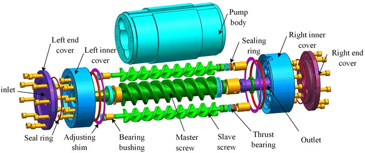
Fig. 2 shows the structural features of the embedded triple screw pump. The figure shows that the suction and discharge ports of the pump are located at both ends of the pump, the master screw and the two slave screws of the pump are placed side by side, the axes of the two slave screws are parallel to the axis of the master screw, and the leads of the slave and master screws are equal and opposite in direction, the two sides of the master screw are hollow. The permanent magnet synchronous motor is fixed on the outside of the pump body, the motor as a whole has a cylindrical structure, the stator and rotor of the motor are coaxially assembled and installed in the motor. The rotor of the motor drives the gear set of the master and slave screws by driving the inner gear ring, thus driving the master and slave screws to rotate; and the stator of the motor is fixed in the central position on the outside of the pump body.
Fig. 2General structure of the embedded triple screw pump
3.2. Calculation model and mesh generation
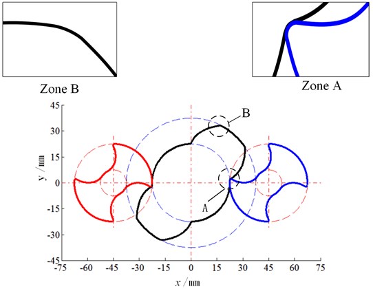
The results of the Matlab parametric calculations of the master and slave screw face profiles and meshing relationships are shown in Fig. 3. In area A of the diagram, a circular transition occurs at the root of the master screw tooth, which makes excessive contact with the optimized top arc of the slave screw tooth. In zone B, a smooth circular arc is obtained by optimizing the tip of the slave screw teeth. The parameters of the master and slave screws are listed in Table 1. By using the sample bar function of the UG software to create the end face geometry of the pump screw, and then generate the helix lead based on the pitch, the number of helix heads, and the helix lift angle, the end face profile geometry was achieved by sweeping the function to generate the screw entity along the helix lead.
Table 1Geometrical parameters of the master and slave screw
Pitch diameter (mm) | Addendum diameter (mm) | Root diameter (mm) | Lead range (mm) | Length (mm) | |
Master screw | 45 | 75 | 45 | 75 | 300 |
Slave screw | 45 | 45 | 15 | 75 | 300 |
Centre distance | 45 | ||||
Radial clearance | 0.1 | ||||
Interlobe clearance | 0.2 | ||||
Fig. 3Tooth profile of the screw end face engagement
Based on the established master and slave screw models with the tooth root circle as the inner boundary and the inner wall surface of the screw bushing as the outer boundary, a screw bushing model was created and then the master and slave screws and screw bushing were subjected to Boolean operations to obtain the internal flow path model of the triple screw pump [21-23]. Owing to the complexity of the screw surfaces, a denser mesh was formed around the screw. The mesh optimization value selected in the Mesh module was 3. To ensure that the boundaries were close to the actual model, a polyhedral mesh was generated and imported into Fluent. The flow field grid model is shown in Fig. 4.
Grid independence: Fig. 5 demonstrates that to verify the grid independence, four check-points were selected on the surface of the screw to compare the equivalent stress values under different grid sizes. Table 2 summarizes that each point was equidistant and four meshes were compared from sparse to dense, making the simulation faster and more accurate. Fig. 6 shows the equivalent stress values of different sizes of grids. The results indicate that when the number of grids ranges from 700,000 to 1,400,000, the change of the equivalent stress values of four points is small. Therefore, it can be proven that the number of grids has little effect on the results, and 782,792 grids can be selected as the calculation grid in this study [24].
Fig. 4Triple screw pump flow-path model
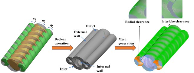
Fig. 5Model of master and slave screw
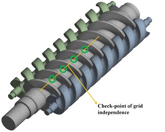
Fig. 6Grid independent verification results
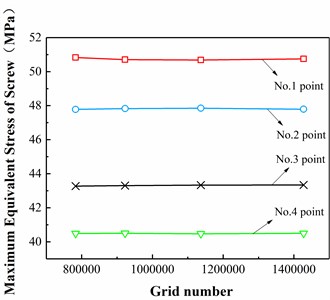
Table 2Grid independence study results
Different grid partitions | 1 | 2 | 3 | 4 |
Total elements | 782792 | 922760 | 1136973 | 1427473 |
Fluid domain | 212972 | 310010 | 411083 | 578313 |
Structure domain | 569820 | 612750 | 725890 | 849160 |
3.3. Boundary conditions
For investigating the complex turbulent flow field in the triple screw pump, a two-squared -epsilon (-) turbulence model was used for the calculations and a semi-implicit method of pressure connection equations (SIMPLE) was used for the numerical simulation of the triple screw pump with a convergence accuracy of 10–4. The flow field boundary conditions were set for the inlet and outlet pressures (3-5 MPa). Based on the actual operating conditions of the triple screw pump, hydraulic oil No. 46 was used as the delivery medium.
The 38CrMoAl alloy steel was used as the master and slave screw material. When the embedded triple screw pump works, the screw surface temperature is lower than the fluid temperature and thermal convection occurs. Therefore, the convective heat transfer coefficient and ambient temperature must be appropriately set. In the structural solution, the external surface of the fluid and the surface of the screw are used as the interaction surfaces, and the master and slave screws of the triple screw pump are supported by the two end constraints.
3.4. Verification of the thermal-fluid-structure coupling calculation
In order to verify the reliability of the proposed method, the pipeline used in literature study [25-27] was selected as the research object. According to the geometric model data provided in the literature, as shown in Fig. 7, the geometric model and the mesh generation model of the pipeline were established. Based on the boundary conditions provided in the literature, the flow field in the pipeline was analyzed by using Fluent®. The inlet was the pressure inlet, whereas the pressure value was 1.6 MPa. The outlet represented the pressure outlet, and the pressure value was 1.4 MPa. The fluid in the pipeline was water and the material used for the pipeline was Q235B.
Fig. 7Verification of the pipeline model
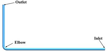
a) Pipe model
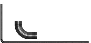
b) Pipe grid model
After Fluent simulation analysis, the results presented in Table 3 show the comparison with the experimental data provided in literature. According to the results, the error was less than 1 %, thus the results are close to the experimental data.
Table 3Comparison with the experimental data
Monitoring parameters | Experimental result | Simulation results | Error |
Inlet velocity (m·s-1) | 4.13 | 4.16 | 0.7 % |
Inlet temperature (K) | 412.5 | 413 | 0.1 % |
Outlet temperature (K) | 411.6 | 412.76 | 0.28 % |
Inlet gauge pressure (Pa) | 1590300 | 1591370 | 0.07 % |
Outlet gauge pressure (Pa) | 1580310 | 1584784 | 0.3 % |
Fig. 8Deformation of pipeline
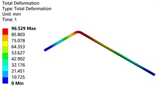
a) Temperature load
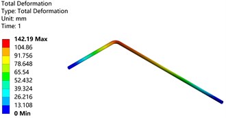
b) Pressure load
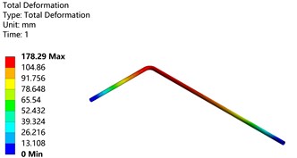
c) Thermal-fluid-structure coupling
Fig. 8 shows the maximum deformation program of pipeline structure under temperature load, pressure load, and thermal-fluid-structure coupling load. Compared with the simulation results in the literature, the maximum deformation under temperature load was 97.037 mm, the maximum deformation under pressure load was 143.6 mm, and the maximum deformation under thermal-fluid-structure coupling load was 178.43 mm, the error was found to be about 2 %. This indicates that the proposed method is feasible and the obtained results are accurate.
4. Numerical analysis results
4.1. Comparison of experimental data
The accuracy of the numerical model was verified through experimental testing of the output flow rate of the embedded triple screw pump. The actual output flow rate of the triple screw pump was measured by varying the output pressure of the pump (1-7 MPa) and compared with the simulated flow rate. The specific values of the experimental results in each case were omitted due to the space constraints. Table 4 presents the comparative analysis of the experimental data with the simulated data, exhibiting that the simulated values are slightly higher than the experimental values under the same conditions, but the difference in flow rate values is less than 10 %. The experimental results follow the same trend as the simulation results [28]. This is attributed to the fact that the numerical analysis is simulated under ideal conditions, and thus some errors are encountered in the processing, assembly, and manufacturing of the screw during the experimental process. Therefore, the simulated value is slightly higher than the experimental value under the same conditions.
Table 4Comparison of experimental data of pump flow
Parameters | Experimental results | Numerical simulation results |
1 MPa | 99.6 L/min | 111.32 L/min |
2 MPa | 98.8 L/min | 109.52 L/min |
3 MPa | 97.5 L/min | 107.62 L/min |
4 MPa | 95.7 L/min | 106.38 L/min |
5 MPa | 94.2 L/min | 104.52 L/min |
6 MPa | 93.9 L/min | 103.14 L/min |
7 MPa | 92.3 L/min | 101.11 L/min |
4.2. Analysis of the temperature and pressure fields in the flow field
Fig. 9 shows that the Fluent® was used to analyze the internal flow field of the triple screw pump. Fig. 9(a) exhibits the pressure distribution of the triple screw pump. The pressure value of the triple screw pump flow passage from the inlet to the outlet increases in a significant step, whereas the pressure value at the screw edge also increases significantly. Fig. 9(b) shows the temperature distribution in the triple screw pump that was obtained by simulating the temperature. Clearly, the temperature gradually increases from the inlet to the outlet. The temperature distribution is regular, and the steps from low temperature to high temperature are clear. It was observed that the temperature near the wall of the screw was relatively high, while the temperature near the surface of the pump body was relatively low because the heat was mainly contributed by the viscous dissipation of the fluid and the heat transfer from the motor to the pump body. Fig. 9(c) shows the temperature distribution of the cross-section at different positions in the flow direction, and further compares and analyzes the temperature distribution of each section. The fluid temperature at the engagement of the master and slave screws was relatively high. This is attributed to the large regional shear speed in the closed space. The viscosity of the fluid body was small. The viscosity generated more heat, thus the temperature became relatively high. Fig. 9(d) shows the temperature distribution of the meshing section. As the triple screw pump compresses and transports the fluid from the inlet to the outlet, the pressure continues to increase from the upper channel to the lower channel. Therefore, the temperature in the upper part of the channel is higher than that in the lower part.
Fig. 9Temperature field distribution
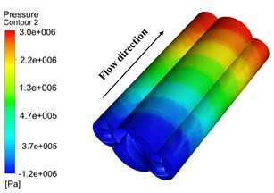
a) Global flow field contour map for pressure
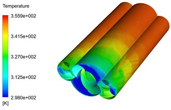
b) Global flow field contour map for temperature
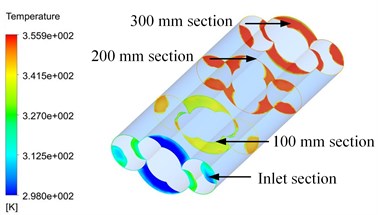
c) Temperature show at different cross-section planes along the axial position
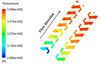
d) Sectional temperature of the flow passage
4.3. Analysis of solid domain temperature fields and structural deformation
Owing to the space limitation, the temperature field of the screw was studied only when the fluid temperature was 80 °C. Figs. 10(a) and 10(b) exhibit that the thermal analysis of the pump at 80 °C shows the changes in the temperature field of the main and secondary screws. The results showed that the inlet temperature was the lowest, while the temperature near the outlet screw edge was higher. Moreover, the temperature at the engagement between the screws was higher than that at other positions. In the high-temperature part of the master screw, the temperature of the tooth surface was 76.25 °C, while the temperature of the axis at the same position was 71.1 °C. This is attributed to the fact that the surface of the tooth can directly contact the heat source, which can better absorb heat from the heat source. Furthermore, the axis conducts heat through the tooth surface, and the absorption of heat becomes slower and is less than that of the tooth’s surface.
Fig. 10Temperature field of screw
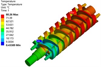
a) Screw surface temperature field
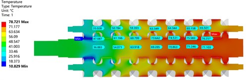
b) Temperature field section
When the temperature in the pump is 80 °C, the driving and driven screws were studied and analyzed, as shown in Fig. 11, respectively, under the temperature load, pressure load, and coupling load. The figure illustrates that the maximum deformation of the screws under temperature load alone is 0.24003 mm, which occurs at the end of the screws. Owing to the constraint of one end of the screws, one end of the screws is free to cause thermal expansion. The maximum deformation under pressure load is 0.34428 mm, which is located on the outside of the driven screw. Owing to the reaction force of fluid pressure, the driven screw expands outwards. Under the coupling action of temperature and pressure load, the maximum deformation of the screws is 0.3805 mm, which is located on the outside of the driven screw. It can thus be concluded that the deformation of the screws in this stage is mainly affected by the fluid pressure, while the temperature is less affected.
Fig. 11Deformation of screw
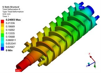
a) Temperature load
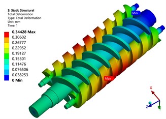
b) Pressure load
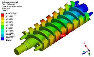
c) Thermal-fluid-structure coupling
Fig. 12Equivalent stress of screw
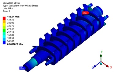
a) Temperature load
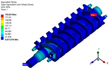
b) Pressure load
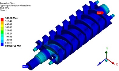
c) Thermal-fluid-structure coupling
Fig. 12 shows that the maximum stress of the screw is 488.64 MPa under temperature load only. The maximum flow field stress under pressure load is 192.83 MPa. However, under the coupling action of temperature and pressure load, the maximum stress of the screw is 583.28 MPa. Under all three loads, the maximum equivalent stress is located at the engagement of the master and slave screws. Numerically, it can be concluded that the stress of the master and slave screws is mainly affected by the fluid temperature.
The safety of a screw is usually defined in terms of the maximum equivalent stress. However, the structural deformation of the screw corresponds to the stress level of the screw. A relationship exists between the deformation of the screw and the equivalent effective stress, and the two parameters show a similar or corresponding relationship. However, the deformation itself is also a form of loading of the screw. Therefore, when equivalent stress is analyzed, the structural deformation should be investigated separately. For the master and slave screw as a whole, the greater the deformation, the greater the stress relief, and the less likely it is that the stress gets concentrated. As an important core component of a triple screw pump, the maximum deformation of the master and slave screws directly affects the safety of the entire screw pump. Therefore, structural deformation and equivalent stresses are important indicators of the safety and stability of a triple screw pump.
Depending on the actual engineering environment (pressure: 3-5 MPa; temperature: 40-80 °C), different pressures (3, 3.5, 4, 4.5, and 5 MPa) were selected for different pump temperatures (40, 50, 60, 70, and 80 °C). Numerical simulations of coupled and uncoupled loads were performed for the master and slave screws of the embedded triple screw pump, which were subjected to single and multiple loads, respectively. The deformation and equivalent stress characteristics of the screw as a whole and the master and slave parts were analyzed.
Table 5The maximum equivalent stress and deformation of the master screw under different temperature conditions
Temperature (°C) | Maximum deformation (mm) | Maximum equivalent stress (MPa) | ||||||
Temperature load | Pressure load | Non-coupled load | Coupled load | Temperature load | Pressure load | Non-coupled load | Coupled load | |
40 | 0.081 | 0.017 | 0.098 | 0.085 | 170.67 | 111.01 | 281.68 | 196.57 |
50 | 0.121 | 0.017 | 0.137 | 0.124 | 254.51 | 111.01 | 357.24 | 293.13 |
60 | 0.160 | 0.017 | 0.177 | 0.164 | 320.85 | 111.01 | 431.86 | 390.06 |
70 | 0.200 | 0.017 | 0.217 | 0.203 | 404.68 | 111.01 | 515.69 | 486.96 |
80 | 0.240 | 0.017 | 0.257 | 0.243 | 488.64 | 111.01 | 559.65 | 583.28 |
Table 6The maximum equivalent stress and deformation of the slave screw under different temperature conditions
Temperature (°C) | Maximum deformation (mm) | Maximum equivalent stress (MPa) | ||||||
Temperature load | Pressure load | Non-coupled load | Coupled load | Temperature load | Pressure load | Non-coupled load | Coupled load | |
40 | 0.066 | 0.344 | 0.410 | 0.343 | 158.01 | 189.03 | 347.04 | 181.97 |
50 | 0.098 | 0.344 | 0.442 | 0.345 | 240.43 | 189.03 | 429.46 | 271.50 |
60 | 0.129 | 0.344 | 0.473 | 0.347 | 307.88 | 189.03 | 496.91 | 361.35 |
70 | 0.162 | 0.344 | 0.506 | 0.351 | 379.04 | 189.03 | 568.07 | 451.17 |
80 | 0.194 | 0.344 | 0.538 | 0.356 | 450.26 | 189.03 | 639.29 | 544.55 |
When the pressure load was 5 MPa, the maximum deformation and maximum equivalent stress of the main screw and driven screw parts were obtained, and the results are presented in Tables 5 and 6. The tables summarize that the maximum equivalent stresses and deformations of the master and slave screws increase with temperature, and the deformations and stresses caused by pressure loads also increase with fluid pressure. When the pressure is certain, the stress and deformation caused by the pressure load do not change with the increase in temperature; however, when the temperature is certain, the deformation and stress of the master and slave screws change with the increase in temperature.
When the temperature fields are analyzed independently, the results indicate that the thermal stresses in the master and slave screws caused by the temperature loads are non-negligible and far greater than those caused by the pressure loads. Notably, the largest equivalent stresses occur at the end of the screw, where the thermal deformation is mainly caused by temperature-induced thermal expansion, as the master and slave screws are supported by bearings at both ends, which constrain the degrees of freedom and prevent the release of stresses. At higher temperatures, the thermal deformation of the master screw is always greater than that of the slave screw.
When the pressure field is analyzed in isolation, the fluid pressure exerts a small effect on the deformation and stress generated by the master and slave screws when the pressure is small. With the increase in the pressure, the reaction force from the high velocity fluid causes the deformation and stress in the master and slave screws to increase. With the increased pressure, the impact of the fluid on the slave screw becomes gradually greater than the impact on the master screw, and the maximum equivalent stress and deformation of the slave screw are already significantly greater than the maximum equivalent stress and deformation of the master screw. Therefore, the deformation effect of the high pressure on the screw and the stress effect of the high temperature on the screw should be taken into account when designing.
When the pressure is 5 MPa, the change of the entire screw under different temperatures is selected and further investigated. Table 7 summarizes that the maximum deformation and equivalent stress of the entire screw increase with the increase of temperature, while the deformation and equivalent stress of pressure load do not change with the increase of temperature. The thermal deformation is less than that caused by pressure load, and the thermal stress is greater than that caused by pressure load when the temperature is high. Therefore, under certain working pressure and abnormal structure temperature, the influence of variation of temperature on the structure should be considered while analyzing and calculating the screw. The thermal stress load caused by high temperature may cause damage.
When the temperature is 80 °C, under the coupling effect of pressure load and temperature load in the flow field, the equivalent stress value of the screw is the largest, corresponding to 583.28 MPa. This value (583.28 MPa) is greater than the allowable stress of 557 MPa. Therefore, the structural strength does not meet the requirements, and materials with higher strength should be considered as potential alternatives. The higher the fluid temperature, the greater the value of the maximum stress. Therefore, the strength of the material should be considered in the design of the three screw pump.
Table 7The maximum equivalent stress and deformation of the whole screw under different temperature conditions
Temperature (°C) | Maximum deformation (mm) | Maximum equivalent stress (MPa) | ||||||
Temperature load | Pressure load | Non-coupled load | Coupled load | Temperature load | Pressure load | Non-coupled load | Coupled load | |
40 | 0.081 | 0.344 | 0.425 | 0.345 | 170.67 | 192.83 | 363.5 | 214.38 |
50 | 0.121 | 0.344 | 0.465 | 0.352 | 254.51 | 192.83 | 447.34 | 292.1 |
60 | 0.160 | 0.344 | 0.504 | 0.360 | 320.85 | 192.83 | 513.68 | 388.95 |
70 | 0.200 | 0.344 | 0.544 | 0.370 | 404.68 | 192.83 | 597.51 | 486.1 |
80 | 0.240 | 0.344 | 0.584 | 0.381 | 488.64 | 192.83 | 681.47 | 583.28 |
4.4. Comparison of screw deformation under different loading conditions and coupling
The above mentioned analysis of temperature load and pressure load indicates that the two types of the load should work together, and then should be comprehensively analyzed in detail. According to the master screw and slave screw, two types of load coupling and uncoupled loading were investigated, and then the results of the above mentioned single load were compared.
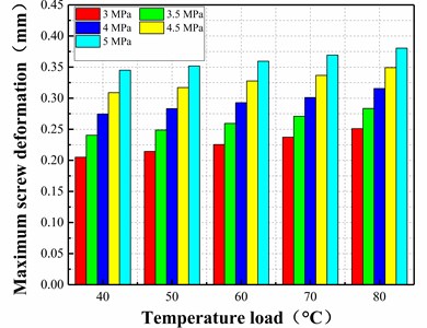
Fig. 13 demonstrates that under actual operating conditions, when the master and slave screws are subjected to coupled temperature and pressure loads, the maximum equivalent stress in the screw also occurs in the slave screw, with the effect of temperature load on the equivalent forces in the master and slave screws being the main factor. Although the effect of fluid pressure on the equivalent stress in the master and slave screws increases with increasing pressure load, the effect is significantly greater than that under the temperature load. Under coupled conditions, the maximum deformation and the equivalent stress across the screw increase linearly. When the temperature increases by 1 °C, the maximum deformation increases by 0.0009 mm and the maximum equivalent force increases by 9.2 MPa.
Fig. 13Variations in the deformation and stress of screw with temperature under different conditions
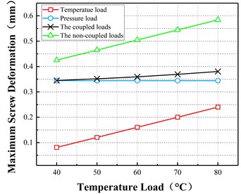
a) Maximum deformation vs temperature load
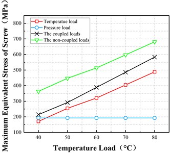
b) Maximum stress vs temperature load
The temperature inside the pump was set at 80 °C and the maximum deformation and equivalent stresses of the screw were compared for the three operating conditions of temperature load, pressure load, and coupled load.
Fig. 14Variations in the deformation and stress of screw with pressure under different conditions
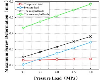
a) Maximum deformation vs pressure load
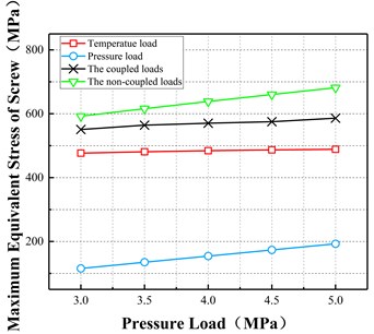
b) Maximum stress vs pressure load
Fig. 14 illustrates that when the master and slave screws are subjected to coupled temperature and pressure loads, the maximum deformation of the screw occurs in the slave screw and the effect of pressure load on the deformation of the master and slave screws is the main factor. With the increase in the pressure load, the effect of pressure on the deformation of the master and slave screws increases. At low pressures, the effect of temperature load is greater than that of pressure load. At high pressures, the effect of pressure load is much greater than that of temperature load. Under coupled conditions, the maximum deformation and the maximum equivalent stress of the entire screw increase linearly. When the pressure increases by 0.1 MPa, the maximum deformation increases by 0.0064 mm and the maximum equivalent stress increases by 1.78 MPa.
Under the conditions studied, when temperature and pressure loads act together, the stress values under the coupled action of the two loads are not equal to the sum of the stress values under the two loads acting separately. This clearly indicates that the pressure and temperature loads do not act on the screw alone, but are coupled together to affect the deformation and equivalent stresses in the screw. When the loads are coupled, the maximum deformation and the maximum equivalent stress of the entire screw are significantly reduced compared to the calculated results without coupling. When the coupling effect exists between the screw loads, the deformation and equivalent stresses in each part become greater than the single load but less than the linear sum of the two loads. In order to further observe the coupling strength, different loads should be used to analyze the deformation and equivalent stresses of the entire screw.
4.5. Effect of coupling action on screw at different temperatures
The deformation of the screw is mainly influenced by the pressure load, and the impact becomes greater with the increase in the pressure. Therefore, the influence of variation in pressure on the structure should be taken into account when carrying out analytical calculations for screws at certain operating temperatures and at different structural pressures. With the increase in the temperature, the effect of pressure loading gradually increases, but still accounts for a large proportion.
Fig. 15 exhibits that the maximum deformation characteristic curve of the screw under coupled thermal-fluid-structure load was obtained by simulation when the fluid pressure was changed from 3 to 5 MPa and the temperature inside the pump was changed from 40 to 80 °C. The results show that the maximum deformation of the screw increases with the increase in temperature. As the pressure changes, the maximum deformation of the screw gradually increases. In the low-pressure region (3 MPa) the deformation increases by approximately 0.0011 mm with the increase in the fluid temperature. In the high-pressure region (5 MPa), the deformation increases by approximately 0.0009 mm as the fluid temperature increases. In the low-temperature region (40 °C), the deformation increases by approximately 0.007 mm as the fluid pressure increases by 0.1 MPa, in the high-temperature region (80 °C) the deformation increases by approximately 0.007 mm as the fluid pressure increases by approximately 0.006 mm when the fluid pressure increases by 0.1 MPa. The results show that the heat-flow-solid coupling effect increases with increasing fluid pressure and temperature. At low temperatures and pressures, the deformation increases rapidly. However, when the deformation reaches a certain level, it does not continue to increase further and the maximum deformation enters a convergence state.
Fig. 15Variations in the deformation of screw with temperature at different pressures
Through numerical analysis and calculations, the deformation patterns of the screw in different directions under different pump temperatures were obtained, whereas the deformation curves of the master and slave screw in different directions under different loads are shown in Fig. 16.
Fig. 16 demonstrates that for the deformation of screw in all directions under the pressure load of 5 MPa, the deformation in direction showed a small increasing trend and the deformation increased uniformly by 0.002 mm with the increase in the temperature of the fluid by 1 °C. The direction deformation was mainly affected by the temperature. With the increase of temperature, an obvious increasing trend was observed, and the deformation increased uniformly by 0.027 mm with the increase in the temperature of the fluid by 1 °C. The deformation in direction decreased gradually with the increase of temperature. This can be attributed to the fact that, when the screw is in the low-temperature zone, the main factor of screw deformation is that the influence of pressure load is relatively large, while the influence of temperature load is relatively small. With the increase of temperature, the influence of temperature load increased gradually, due to which, the deformation in -direction decreased gradually.
Under the temperature load of 80 °C, with the increase of pressure, the deformation in the direction was much larger than that in the and directions, and the deformation in , , and directions increased linearly. Moreover, the deformation in the direction was mainly affected by the pressure load, and the deformation increased uniformly by 0.03 mm with the increase in the pressure of the fluid by 0.1 MPa. However, the deformation of and directions increased uniformly by 0.02 and 0.004 mm, respectively, with the increase in the pressure of the fluid by 0.1 MPa. Consequently, pressure load was the main factor of screw deformation, and the effect of temperature load on the screw was far less than that of the pressure load.
Fig. 16Variations in the deformation of screw with temperature and pressure in different directions
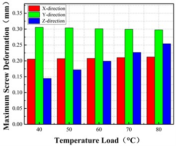
a) Maximum deformation vs temperature load
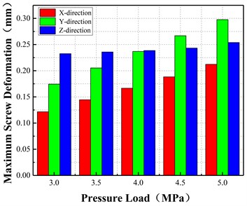
b) Maximum deformation vs pressure load
4.6. Effect of coupling action on maximum deformation of master and slave screw
In order to better observe the temperature load and pressure load on the main and slave screw deformation. Use the path command in ANSYS Workbench to set the axial path of the master and slave screw, as shown in Fig. 17. A-1 to A-2 is the path setting of the master screw, B-1 to B-2 is the path setting of the slave screw.
Fig. 17Axial path setting of master and slave screw
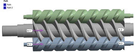
Fig. 18(a) exhibits that the maximum deformation of the master screw decreases along the axial length from 0 to 300 mm, indicating that the maximum deformation of the master screw occurs mainly at the pump inlet. However, at different fluid pressures, the maximum deformation increases gradually with increasing fluid pressure. Fig. 18(b) shows the maximum deformation of the slave screw along its axial length. The maximum deformation of the slave screw occurs at an axial distance of between 100 and 200 mm, right in the middle of the slave screw. The maximum deformation of the slave screw is found to occur at the inlet of the pump under the effect of temperature only. In the case of pressure only, the maximum deformation occurred on both sides of the slave screw, due to the compression of the fluid pressure. The maximum deformation position still occurs on both sides of the slave screw under the combined coupling of the two, indicating that the factor affecting the deformation is mainly the pressure condition. The maximum deformation position of the slave screw increases and then decreases along the axial position, and the maximum deformation gradually increases with the increase of pressure. Moreover, the pressure increase has a significant effect on the deformation of the slave screw, while the effect on the deformation of the master screw is relatively small.
Fig. 18Maximum deformation of axial length of master and slave screw under different pressures
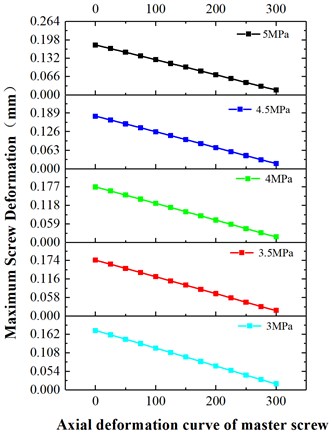
a) Master screw
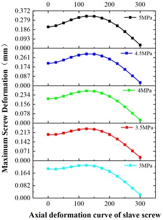
b) Slave screw
5. Conclusions
This study presents a new embedded triple screw pump. The indirect coupling method was used to numerically simulate the temperature, pressure, and stress fields of the embedded triple screw pump. The structural characteristics of the pump under different operating conditions were analyzed and the deformation distribution laws of the master and slave screws under temperature load, pressure load, and coupling load were obtained. Following conclusions can be drawn:
1) Pressure and temperature loads interact with each other and affect the deformation and stresses in the screw at the same time. The deformation and stresses under the coupling load are less than the sum of those under the pressure and temperature loads.
2) The stresses in the master and slave screws are mainly influenced by the fluid temperature, with the coupling effect becoming greater with the increase in the temperature. The deformation of the master and slave screws is mainly influenced by the pressure, the impact force gradually decreases, but the pressure load still dominates.
3) Under a pressure load of 5 MPa, the deformation in the direction shows a slight increase with the increase of temperature. The deformation in the direction is mainly affected by temperature, which shows a significant increasing trend with increasing temperature. The deformation in the -direction gradually decreases with the increase of temperature. Under a temperature load of 80 °C, the deformation in the , , and directions increases linearly with the increase of pressure.
References
-
Q. Tang and Y. Zhang, “Screw optimization for performance enhancement of a twin-screw pump,” Proceedings of the Institution of Mechanical Engineers, Part E: Journal of Process Mechanical Engineering, Vol. 228, No. 1, pp. 73–84, Feb. 2014, https://doi.org/10.1177/0954408913478602
-
Q. Tang, Y. Zhang, L. Pei, and J. Tang, “Optimal design of screw and flow field analysis for twin-screw pump,” in ASME 2011 International Design Engineering Technical Conferences and Computers and Information in Engineering Conference, pp. 593–600, Jan. 2011, https://doi.org/10.1115/detc2011-48056
-
D. Yan, A. Kovacevic, Q. Tang, and S. Rane, “Numerical investigation of flow characteristics in twin-screw pump under cavitating conditions,” IOP Conference Series: Materials Science and Engineering, Vol. 232, No. 1, p. 012026, Aug. 2017, https://doi.org/10.1088/1757-899x/232/1/012026
-
D. Yan, A. Kovacevic, Q. Tang, S. Rane, and W. Zhang, “Numerical modelling of twin-screw pumps based on computational fluid dynamics,” Proceedings of the Institution of Mechanical Engineers, Part C: Journal of Mechanical Engineering Science, Vol. 231, No. 24, pp. 4617–4634, Dec. 2017, https://doi.org/10.1177/0954406216670684
-
T.-Y. Gao, D.-F. Yang, F. Cao, and J.-C. Jiao, “Temperature and thermodynamic deformation analysis of the rotors on a twin screw multiphase pump with high gas volume fractions,” Journal of Zhejiang University-SCIENCE A, Vol. 12, No. 9, pp. 720–730, Sep. 2011, https://doi.org/10.1631/jzus.a1000485
-
X. Yin, F. Cao, S. Pan, Y. Song, J. Fei, and X. Wang, “Numerical investigation on screw rotor deformation and influence on volumetric efficiency of the twin-screw multiphase pump,” Applied Thermal Engineering, Vol. 111, pp. 1111–1118, Jan. 2017, https://doi.org/10.1016/j.applthermaleng.2016.10.027
-
K. Räbiger, “Fluid dynamic and thermodynamic modelling of multiphase screw pumps, operating on the threshold of an exclusive gas compression,” in 7th International Conference on Compressors and their Systems, pp. 385–400, 2011.
-
S. Rane, A. Kovacevic, N. Stosic, and M. Kethidi, “Grid deformation strategies for CFD analysis of screw compressors,” International Journal of Refrigeration, Vol. 36, No. 7, pp. 1883–1893, Nov. 2013, https://doi.org/10.1016/j.ijrefrig.2013.04.008
-
S. Rane, A. Kovacevic, N. Stosic, and M. Kethidi, “Deforming grid generation and CFD analysis of variable geometry screw compressors,” Computers and Fluids, Vol. 99, pp. 124–141, Jul. 2014, https://doi.org/10.1016/j.compfluid.2014.04.024
-
S. Rane, A. Kovačević, and N. Stošić, “Analytical grid generation for accurate representation of clearances in CFD for screw machines,” IOP Conference Series: Materials Science and Engineering, Vol. 90, No. 1, p. 012008, Aug. 2015, https://doi.org/10.1088/1757-899x/90/1/012008
-
T. N. Mustafin, R. R. Yakupova, A. V. Burmistrova, M. S. Khamidullina, and I. G. Khisameeva, “Analysis of influence of screw compressor construction parameters and working condition on rotor temperature fields,” Procedia Engineering, Vol. 152, pp. 423–433, 2016, https://doi.org/10.1016/j.proeng.2016.07.612
-
N. Seshaiah, S. K. Ghosh, R. K. Sahoo, and S. K. Sarangi, “Mathematical modeling of the working cycle of oil injected rotary twin screw compressor,” Applied Thermal Engineering, Vol. 27, No. 1, pp. 145–155, Jan. 2007, https://doi.org/10.1016/j.applthermaleng.2006.05.007
-
F. Cao, T. Gao, S. Li, Z. Xing, and P. Shu, “Experimental analysis of pressure distribution in a twin screw compressor for multiphase duties,” Experimental Thermal and Fluid Science, Vol. 35, No. 1, pp. 219–225, Jan. 2011, https://doi.org/10.1016/j.expthermflusci.2010.09.004
-
S. H. Hsieh, Y. C. Shih, W.-H. Hsieh, F. Y. Lin, and M. J. Tsai, “Calculation of temperature distributions in the rotors of oil-injected screw compressors,” International Journal of Thermal Sciences, Vol. 50, No. 7, pp. 1271–1284, Jul. 2011, https://doi.org/10.1016/j.ijthermalsci.2011.02.006
-
S. V. Krichel and O. Sawodny, “Dynamic modeling of compressors illustrated by an oil-flooded twin helical screw compressor,” Mechatronics, Vol. 21, No. 1, pp. 77–84, Feb. 2011, https://doi.org/10.1016/j.mechatronics.2010.08.004
-
H. Ding, Y. Jiang, and S. Dhar, “CFD modelling of coupled heat transfer between solid and fluid in a twin screw compressor,” IOP Conference Series: Materials Science and Engineering, Vol. 604, No. 1, p. 012005, Sep. 2019, https://doi.org/10.1088/1757-899x/604/1/012005
-
D. Rowinski, A. Nikolov, and A. Brümmer, “Modeling a dry running twin-screw expander using a coupled thermal-fluid solver with automatic mesh generation,” IOP Conference Series: Materials Science and Engineering, Vol. 425, No. 1, p. 012019, Nov. 2018, https://doi.org/10.1088/1757-899x/425/1/012019
-
J. Wei, Q. Sun, X. Sun, and W. Sun, “A study on rotor profiles design for a novel twin-screw kneader,” International Journal of Precision Engineering and Manufacturing, Vol. 14, No. 3, pp. 451–459, Mar. 2013, https://doi.org/10.1007/s12541-013-0061-7
-
J. Wei, “Rotor profiles design method and numerical simulation for twin-screw kneader,” Journal of Mechanical Engineering, Vol. 49, No. 3, p. 63, 2013, https://doi.org/10.3901/jme.2013.03.063
-
S. R. P. Arumugam et al., “CFD modelling and performance analysis of a twin screw hydrogen extruder,” Fusion Engineering and Design, Vol. 138, pp. 151–158, Jan. 2019, https://doi.org/10.1016/j.fusengdes.2018.11.014
-
Y. Zhao, S. Zhao, H. Hou, J. Li, and W. Wei, “Determining the repair width and CNC grinding of screws of triple-screw pump,” The International Journal of Advanced Manufacturing Technology, Vol. 97, No. 1-4, pp. 389–400, Jul. 2018, https://doi.org/10.1007/s00170-018-1943-8
-
Y. Zhao, S. Zhao, W. Wei, and H. Hou, “Precision grinding of screw rotors using CNC method,” The International Journal of Advanced Manufacturing Technology, Vol. 89, No. 9-12, pp. 2967–2979, Apr. 2017, https://doi.org/10.1007/s00170-016-9241-9
-
P. Dong, S. Zhao, Y. Zhao, P. Zhang, and Y. Wang, “Design and experimental analysis of end face profile of tri-screw pump,” Proceedings of the Institution of Mechanical Engineers, Part A: Journal of Power and Energy, Vol. 234, No. 4, pp. 481–489, Jun. 2020, https://doi.org/10.1177/0957650919870373
-
Y. Zhao, B. Zhu, H. Hou, and S. Zhao, “Performance analysis of embedded tri-screw pump based on computational fluid dynamics,” Journal of Mechanical Science and Technology, Vol. 35, No. 2, pp. 601–614, Feb. 2021, https://doi.org/10.1007/s12206-021-0120-4
-
Xu, Q., Feng, and J.-X., “Effects of different loads on structure deformation of "L"-type large-diameter buried pipe network based on flow-heat-solid coupling,” Heat Transfer-Asian Research, Vol. 46, No. 8, pp. 1327–1341, 2017.
-
Xu, Q., Feng, J., Zhang, and S., “Effects of different loads on structure stress of "L"-type large-diameter buried pipe network based on fluid-structure-heat coupling,” International Communications in Heat and Mass Transfer, Vol. 86, pp. 222–230, 2017.
-
Xu, Q., Feng, J., Zhang, and S., “Combined effects of different temperature and pressure loads on the "L"-type large-diameter buried pipeline,” International Journal of Heat and Mass Transfer, Vol. 111, pp. 953–961, 2017.
-
M. Zhu, S. Zhao, J. Li, and P. Dong, “Computational fluid dynamics and experimental analysis on flow rate and torques of a servo direct drive rotary control valve,” Proceedings of the Institution of Mechanical Engineers, Part C: Journal of Mechanical Engineering Science, Vol. 233, No. 1, pp. 213–226, Jan. 2019, https://doi.org/10.1177/0954406218756449
About this article

The author(s) disclosed receipt of the following financial support for the research, authorship, and/or publication of this article: This work was supported by the Natural Science Foundation of Shaanxi Province of China (Grant No. 2019JM-466), and Opening Foundation t of Shaanxi Key Laboratory of Industrial Automation (Grant No. SLGPT2019KF01-19).
